bolt BMW 528i 1999 E39 Repair Manual
[x] Cancel search | Manufacturer: BMW, Model Year: 1999, Model line: 528i, Model: BMW 528i 1999 E39Pages: 1002
Page 165 of 1002
Downloaded from www.Manualslib.com manuals search engine
. ." . .
I - Cylinder Head Removal - and instard --
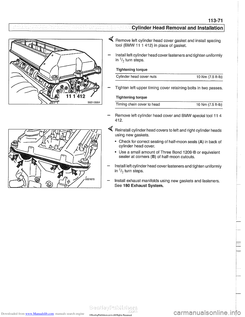
4 Remove left cylinder head cover gasket and install spacing
tool (BMW
11 1 412) in place of gasket.
- lnstall lefl cylinder head cover fasteners and tighten uniformly
in
'I2 turn steps.
Tightening torque Cylinder head cover nuts
10 Nrn (7.5 it-lb)
- Tighten left upper timing cover retaining bolts in two passes.
Tightening torque
Timing chain cover to head 10 Nrn (7.5 ft-lb)
- Remove lefl cylinder head cover and BMW special tool 11 4
412.
4 Reinstall cylinder head covers to left and right cylinder heads
using new gaskets.
Check for correct seating of half-moon seals
(A) in back of
cylinder head cover.
Use a small amount of Three Bond 1209
03 or equivalent
sealer at corners
(6) of half-moon cutouts.
- Install left cylinder head cover fasteners and tighten uniformly
in
'I? turn steps.
- Install exhaust manifolds using new gaskets and fasteners.
See
180 Exhaust System.
Page 167 of 1002
Downloaded from www.Manualslib.com manuals search engine
11 3-73
Cylinder Head Removal and Installation /
1
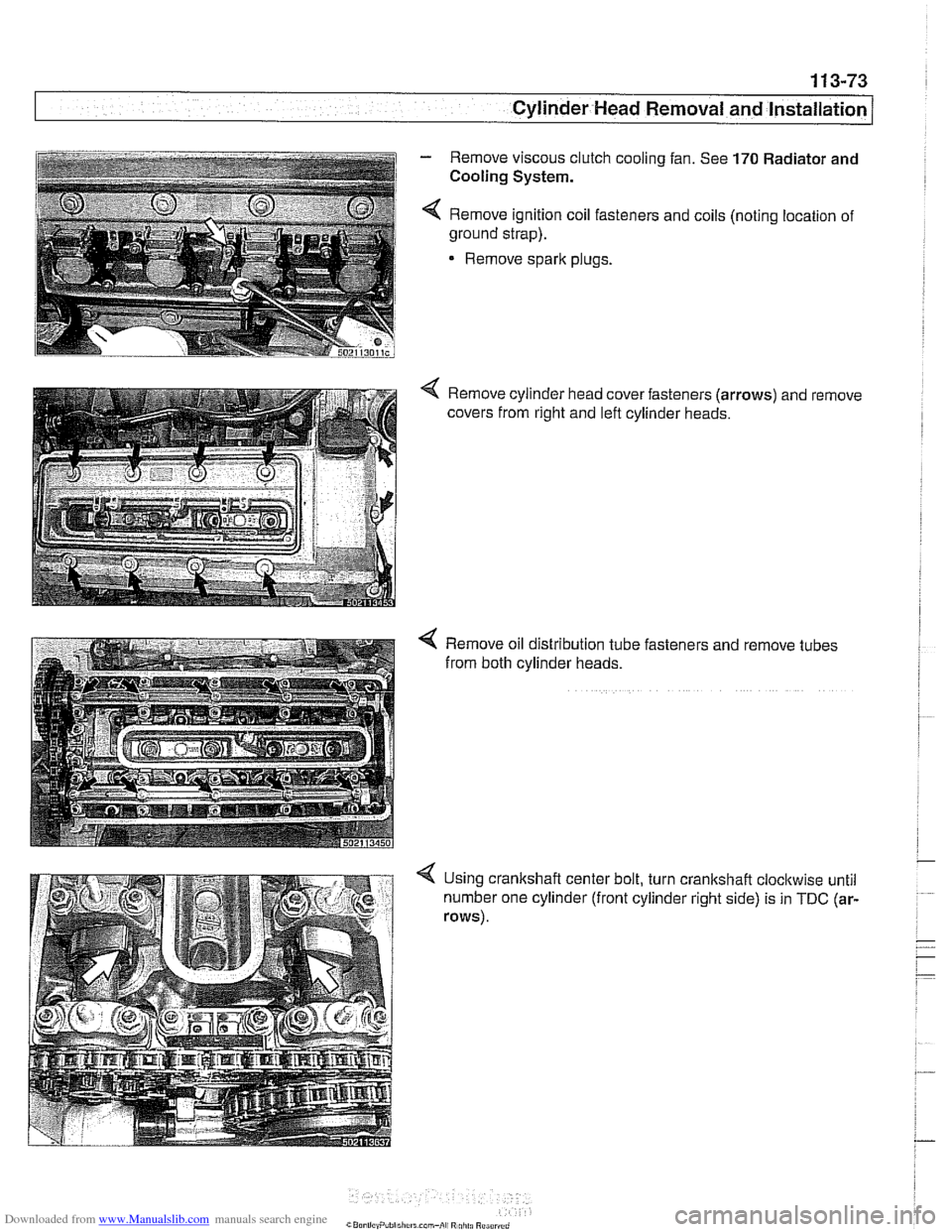
- Remove viscous clutch cooling fan. See 170 Radiator and
i Cooling System. i i I 4 Remove ignition coil fasteners and coils (noting location of
~ ground strap).
1
Remove sparlc plugs.
i
Remove oil distribution tube fasteners and remove tubes
from both cylinder heads.
4 Using crankshaft center bolt, turn crankshaft cloclcwise until
number one cylinder (front cylinder right side) is in
TDC (ar-
rows).
Page 170 of 1002
Downloaded from www.Manualslib.com manuals search engine
1 13-76
Cylinder Head Removal and Installation
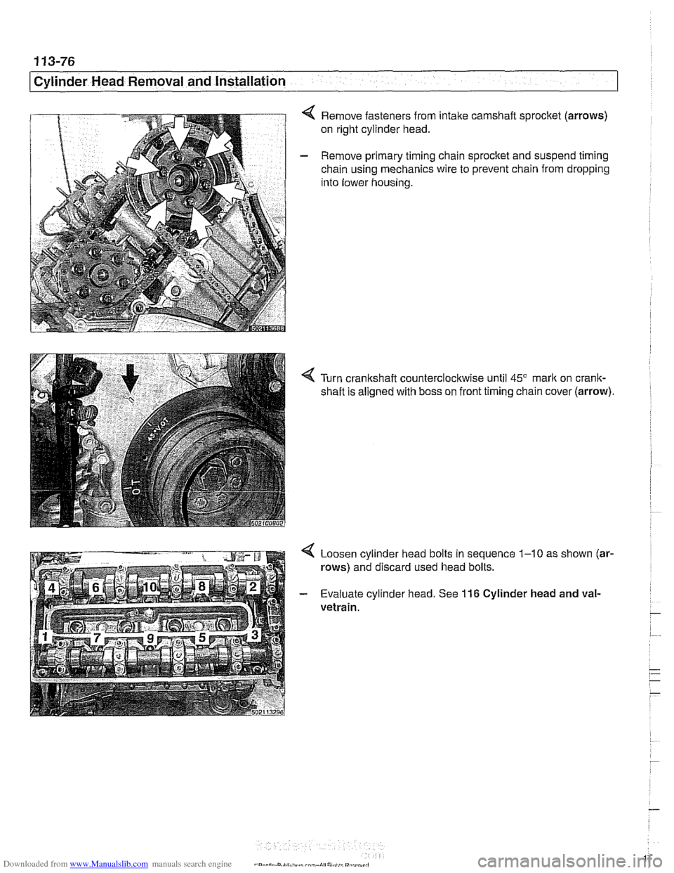
Remove fasteners from intake camshaft sprocket (arrows)
on right cylinder head.
- Remove primary timing chain sprocket and suspend timing
chain using mechanics wire to prevent chain from dropping
into lower housing.
Turn crankshaft counterclockwise until
45" mark on crank-
shaft is aligned with boss on front timing chain cover (arrow)
4 Loosen cylinder head bolts in sequence 1-10 as shown (ar-
rows) and discard used head bolts.
- Evaluate cylinder head. See 116 Cylinder head and val-
vetrain.
Page 171 of 1002
Downloaded from www.Manualslib.com manuals search engine
Cvlinder Head Removal and Installation /
Right cylinder head, installing, M62 engine
- Clean cylinder head and block sealing surfaces of gasket de-
bris, making sure no debris drops into coolant or oil passag-
es.
CA UTIOW-
To prevent valve to piston contact when tightening camshaft
sprocket fasteners, counterhold camshaft with
27 mm open-
end wrench. If
necessarq: grind outer side of wrench jaws to
prevent damaging cylinder head.
- Check cylinder head bolt holes and condition of threads. Re-
move debris and liquids from holes.
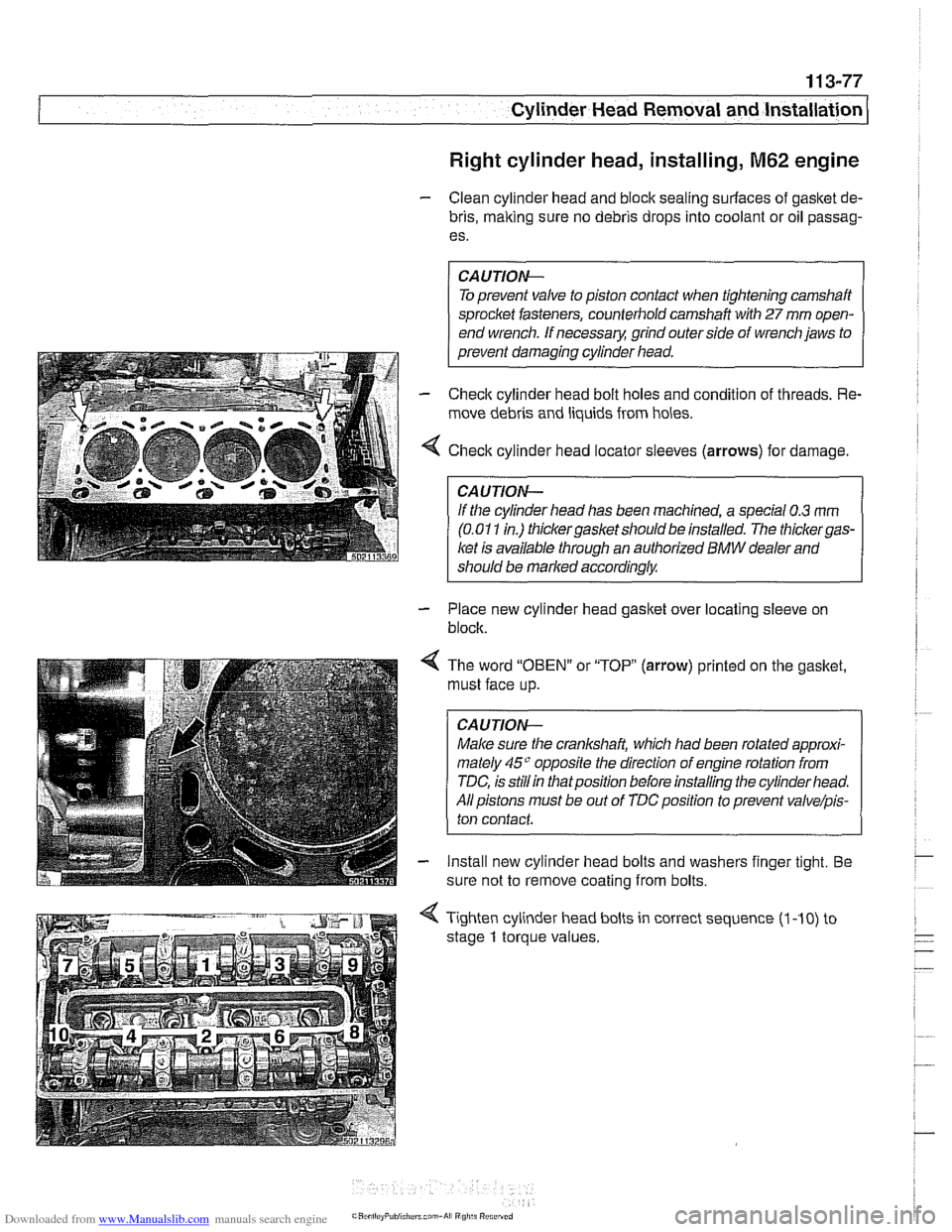
4 Check cylinder head locator sleeves (arrows) for damage
CAUTION-
lithe cylinder head has been machined, a special 0.3 rnm
(0.01 1 in.) thickergasket should be installed. The thickergas-
ket is available through an authorized BMW dealer and
should be marked
accordinglw
- Place new cylinder head gasket over locating sleeve on
block.
< The word "OBEN" or "TOP (arrow) printed on the gasket.
must face up.
CAUTION-
Male sure the crankshaft, which had been rotated approxi-
mately
45" opposite the direction of engine rotation from
TDC, is
stillin thatposition before installing the cylinder head.
All pistons must be out of
TDCposition to prevent valve/pis-
ton contact
- Install new cylinder head bolts and washers finger tight. Be
sure not to remove coating from bolts.
4 Tighten cylinder head bolts in correct sequence (1 -10) to
stage
1 torque values.
Page 172 of 1002
Downloaded from www.Manualslib.com manuals search engine
11 3-78
Cylinder Head Removal and Installation
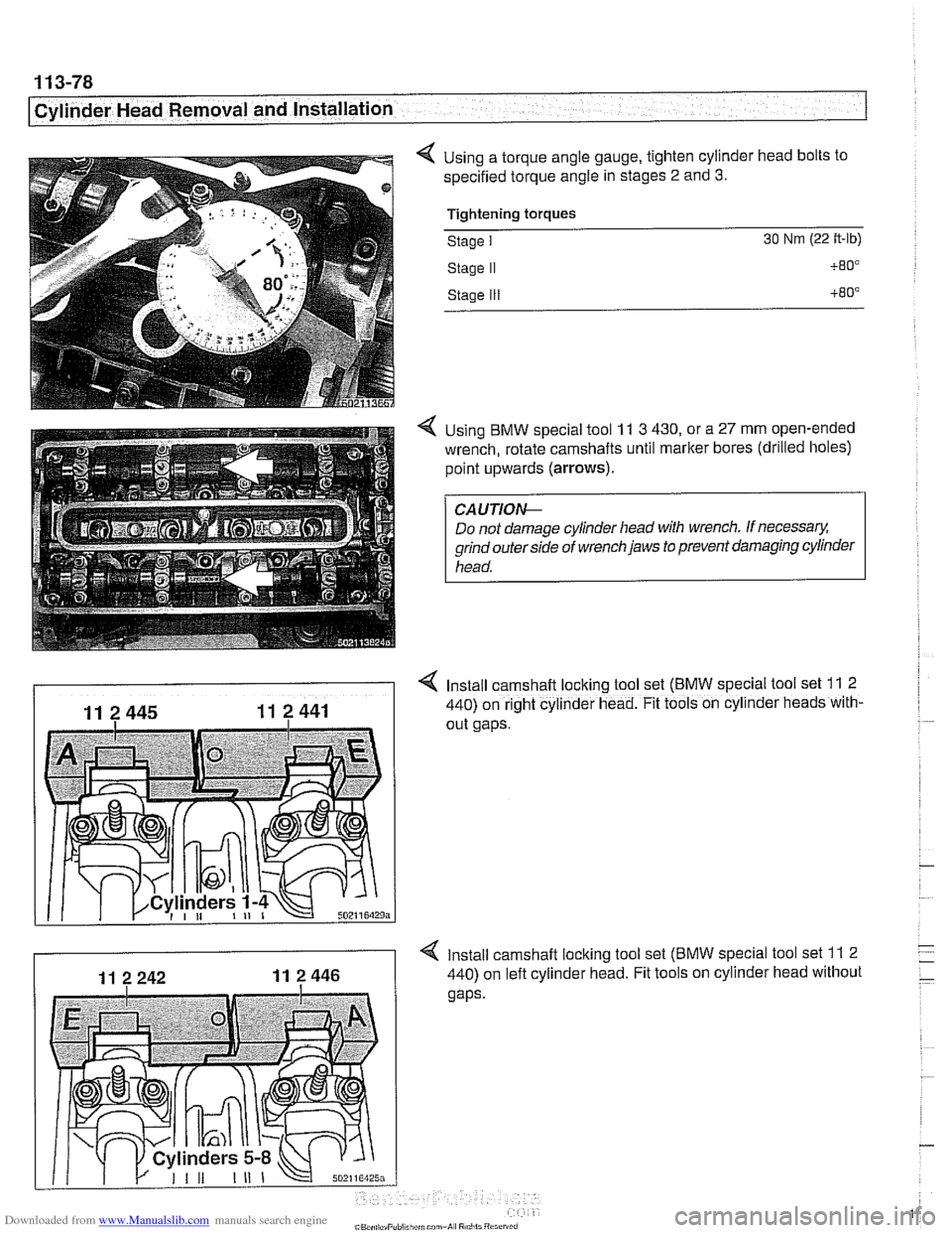
4 Using a torque angle gauge, tighten cylinder head bolts to
specified torque angle in stages
2 and 3.
Tiahtenina toraues - -.
Stage I 30 Nm (22 ft-lb)
Stage I1
Stage Ill
4 Using BMW special tool 11 3 430, or a 27 mm open-ended
wrench, rotate camshafts until marker bores (drilled holes)
point upwards
(arrows).
Do not damage cylinder head with wrench. If necessary.
grind outer side of wrench jaws to prevent damaging cylinder
head.
4 Install camshaft locking tool set (BMW special tool set 11 2
440) on right cylinder head. Fit tools on cyllnder heads with-
out gaps.
4 Install camshaft locking tool set (BMW special tool set 11 2
440) on left cylinder head. Fit tools on cylinder head without
Page 173 of 1002
Downloaded from www.Manualslib.com manuals search engine
-8" ."
Cylinder Head Removal and Installation --
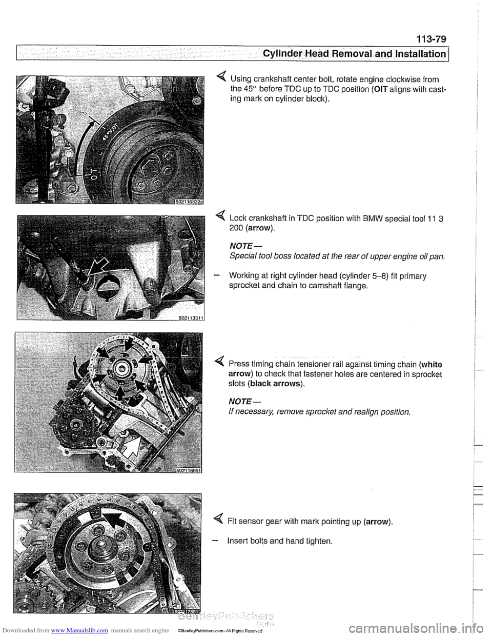
Using crankshaft center bolt, rotate engine clockwise from
the
45" before TDC up to TDC position (OIT aligns with cast-
ing mark on cylinder block).
< Lock crankshaft in TDC position with BMW special tool 11 3
200 (arrow).
NOTE-
Special tool boss located at the rear of upper engine oil pan.
- Working at right cylinder head (cylinder 5-8) fit primary
sprocltet and chain to camshaft flange.
!
I
4 Press timing chain tensioner rail against timing chain (white
arrow) to check that fastener holes are centered in sprocket
slots (black arrows).
NOTE-
If necessary, remove sprocl
Insert bolts and hand tighten.
Page 174 of 1002
Downloaded from www.Manualslib.com manuals search engine
11 3-80
Cylinder Head Removal and lnstallation
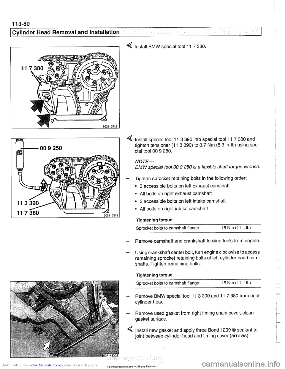
I I 4 Install BMW special tool 11 7 380
4 Install special tool 11 3 390 into special tool 11 7 380 and
tighten tensioner
(1 1 3 390) to 0.7 Nm (6.3 in-lb) using spe-
cial tool 00
9 250.
NOTE-
BMW special tool 00 9 250 is a flexible shaft torque wrench.
- Tighten sprocket retaining bolts in the following order:
3 accessible bolts on left exhaust camshaft
- All bolts on right exhaust camshaft
3 accessible bolts on left intake camshaft
All bolts on right intake camshaft
Tightening torque
Sprocitet bolts to camshaft flange 15 Nm (11 ft-lb)
- Remove camshaft and crankshaft locking tools from engine.
- Using crankshaft center bolt, turn engine clockwise to access
remaining sprocket retaining bolts of left cylinder head cam-
shafts. Tighten remaining bolts.
Tightening torque
Sprocket bolts
to camshaft flange 15 Nm (11 ft-ib)
- Remove BMW special tool 11 3 390 and 11 7 380 from right
cylinder head.
- Remove used gasket from right timing chain cover, clean
gasket surface.
4 Install new gasket and apply three Bond 1209 @sealant to
joint between cylinder head and timing cover
(arrows).
Page 185 of 1002
Downloaded from www.Manualslib.com manuals search engine
11 6-9
Cvlinder Head and valvetrain1
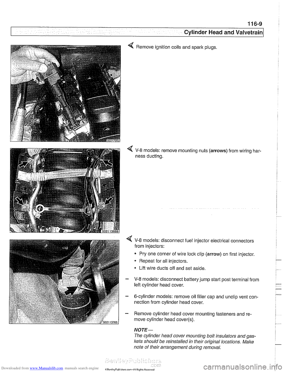
4 Remove ignition coils and spark plugs.
V-8 models: remove mounting nuts (arrows) from wiring har-
ness ducting.
< V-8 models: disconnect fuel injector electrical connectors
from injectors:
Pry one corner of wire
loclc clip (arrow) on first injector.
Repeat for all injectors.
Lift wire ducts off and set aside.
- V-8 models: disconnect battery jump start post terminal from
left cylinder head cover.
- 6-cylinder models: remove oil filler cap and unclip vent con-
nection from cylinder head cover.
- Remove cylinder head cover mounting fasteners and re-
move cylinder head cover(~).
NOTE-
The cylinder head cover mounting bolt insulators and gas-
Icets should be reinstalled in their original locations. Make
note of their arrangement
during removal.
Page 186 of 1002
Downloaded from www.Manualslib.com manuals search engine
Cylinder Head and Valvetrain
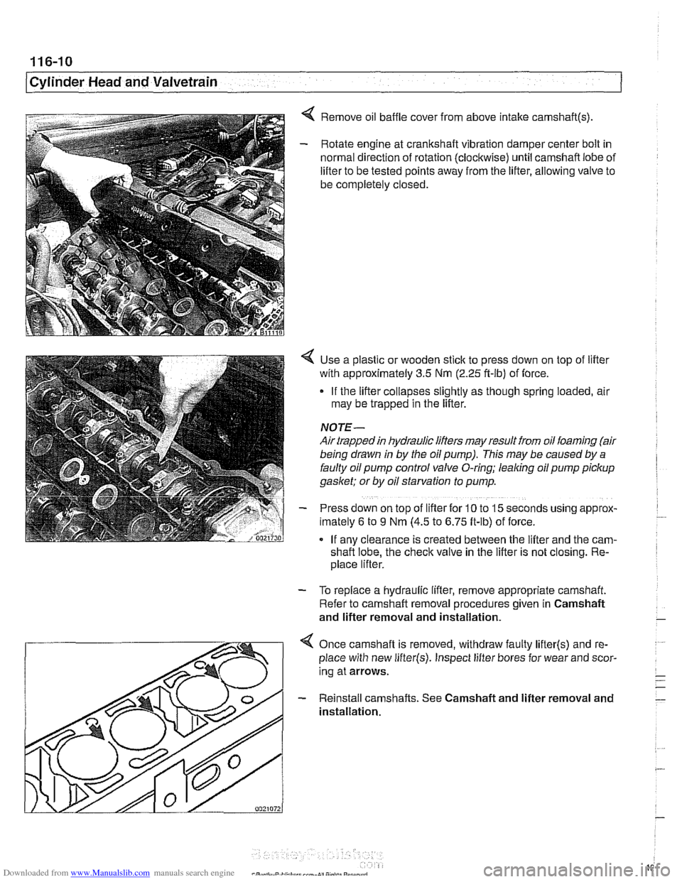
< Remove oil baffle cover from above intake camshaft(s)
- Rotate engine at crankshaft vibration damper center bolt in
normal direction of rotation (clockwise) until camshaft lobe of
lifter to be tested points away from the lifter, allowing valve to
be completely closed.
Use a plastic or wooden stick to press down on top of lifter
with approximately 3.5 Nm
(2.25 ft-ib) of force.
If the lifter collapses slightly as though spring loaded, air
may be trapped in the lifter.
NOTE-
Air trapped in hydraulic lifters may result from oil foaming (air
being drawn
in by the oil pump). This may be caused by a
faulty oil pump control valve O-ring; leaking oil pump pickup
gaslcet; or by oil starvation to pump.
Press down on top of lifter for
10 to 15 seconds uslng approx-
lmately 6 to 9 Nm (4.5 to 6.75 ft-lb) of force.
If anv clearance is created between the lifter and the
cam-
shafi lobe, the check valve in the lifter is not closing. Re-
place lifter.
- To replace a hydraulic lifter, remove appropriate camshaft.
Refer to camshaft removal procedures given in Camshaft
and lifter removal and installation.
Once camshaft is removed, withdraw faulty
lifter(s) and re-
place with new
lifter(s). Inspect lifter bores for wear and scor-
ing at arrows.
- Reinstall camshafts. See Camshaft and lifter removal and
installation.
Page 188 of 1002
Downloaded from www.Manualslib.com manuals search engine
116-12
I Cylinder Head and Valvetrain
Camshaft and lifter removal and installation
(M52 engine)
Camshafts and lifters, removing (M52 engine)
WARNING
-
The process of evenly loosening the camshaft bearing cap
nuts is NOT an acceptable method of removing the cam-
shafts. Special tools should always be used to remove the
camshafts. Be sure to read the procedure
tlirough before
starting a job.
I Allow engine to cool before beginning this procedure. /
- Disconnect negative (-) cable from battery.
CAUTION-
Prior to disconnecting the batfew read the battery discon-
nection cautions given in
001 General Cautions and
Warnings.
- Remove VANOS control unit from cylinder head. See 117
Camshaft Timing Chain.
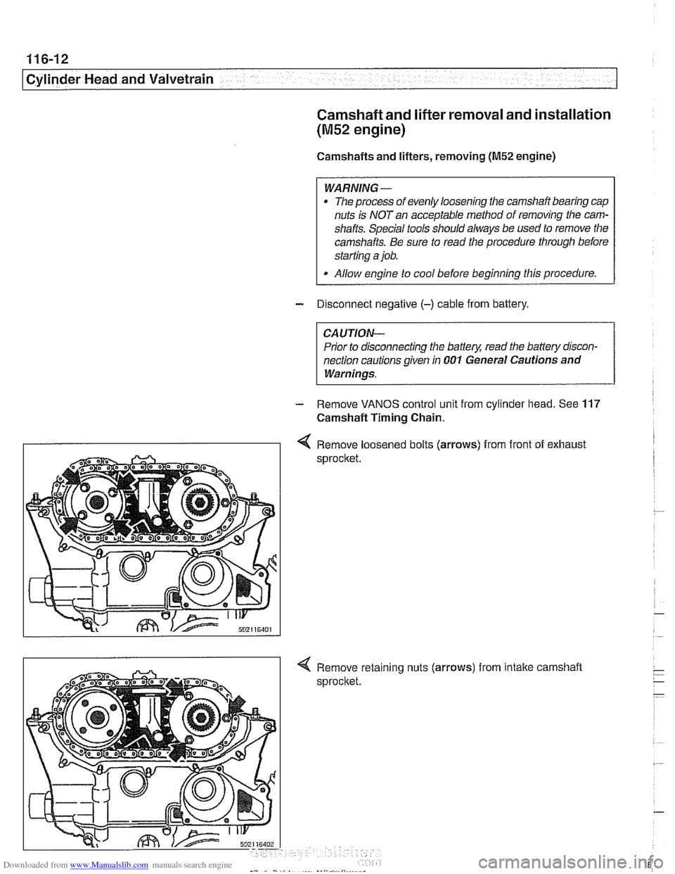
I I 4 Remove loosened bolts (arrows) from front of exhaust
sprocket
nuts
(arrows) from intake camshaft