Reverse BMW 528i 1999 E39 Repair Manual
[x] Cancel search | Manufacturer: BMW, Model Year: 1999, Model line: 528i, Model: BMW 528i 1999 E39Pages: 1002
Page 494 of 1002
Downloaded from www.Manualslib.com manuals search engine
Fuel Tank and Fuel Pump 1
Activated carbon canister I fuel tank leak
detection unit
(LDP or DMTL), removing . . -
and installing
- Raise rear end of car and support safely.
CAUTION-
Make sure the car is stable and well supported at all times.
Use a professional automotive lift
orjack stands designed for
the purpose.
A floor jack is not adequate support.
- Remove left rear wheel and inner fender panel
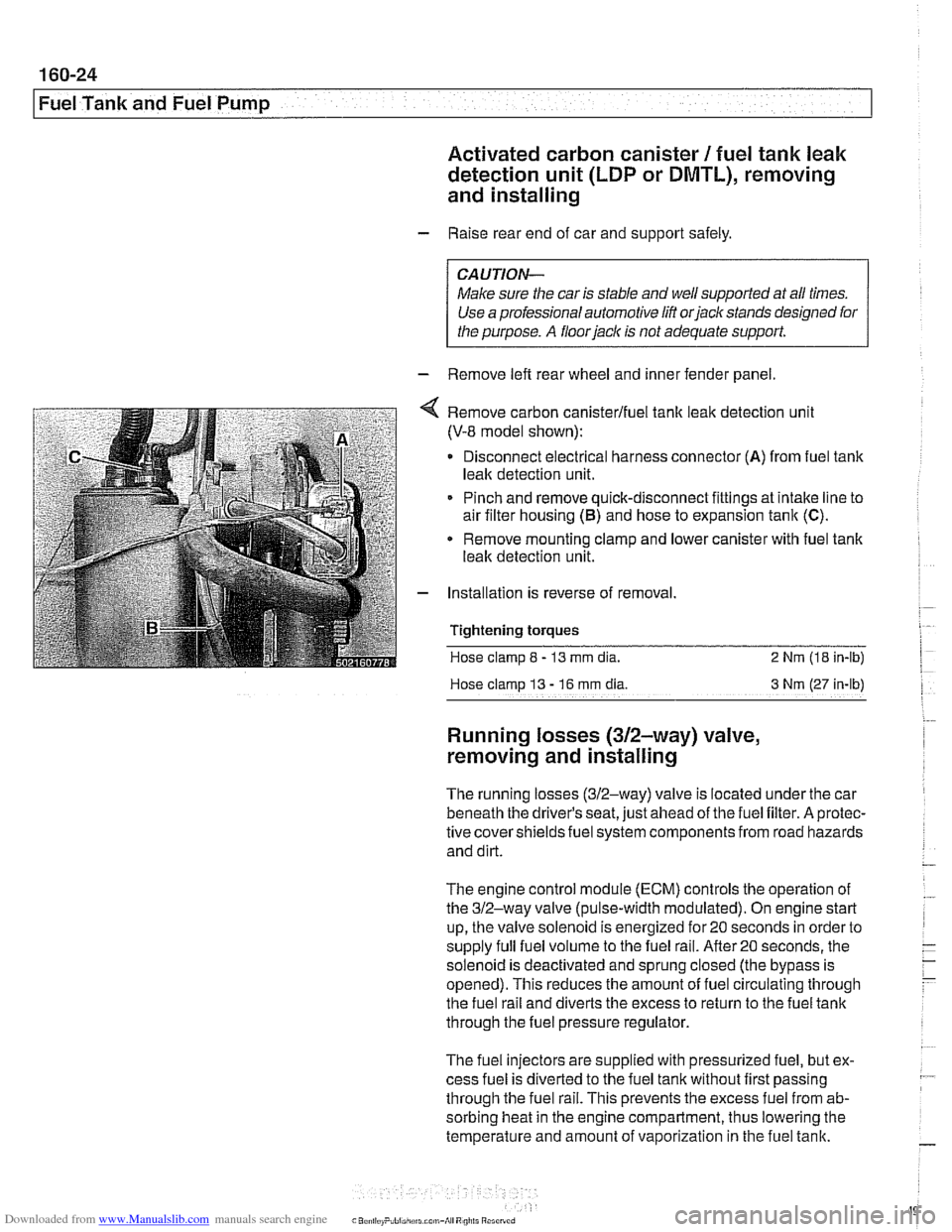
Remove carbon canisterlfuel tank leak detection unit
(V-8 model shown):
Disconnect electrical harness connector
(A) from fuel tank
leak detection unit.
Pinch and remove quick-disconnect fittings at intake line to
air filter housing
(5) and hose to expansion tank (C).
* Remove mounting clamp and lower canister with fuel tank
leak detection unit.
Installation is reverse of removal.
Tightening
torques
Hose clamp 8 - 13 mm dia. 2 Nrn (18 in-lb)
Hose clamp
13 - 16 rnm dia 3 Nm (27 in-lb)
Running losses (312-way) valve,
removing and installing
The running losses (312-way) valve is located under the car
beneath the driver's seat, just ahead of the fuel filter. A protec-
tive covershieldsfuel system components from road hazards
and dirt.
The engine control module
(ECM) controls the operation of
the 312-way valve (pulse-width modulated). On engine start
up, the valve solenoid is energized for 20 seconds in order to
supply full fuel volume to the fuel rail.
After20 seconds, the
solenoid is deactivated and sprung closed (the bypass is
opened). This reduces the amount of fuel circulating through
the fuel rail and diverts the excess to return to the fuel tank
through the fuel pressure regulator.
The fuel injectors are supplied with pressurized fuel, but ex-
cess fuel is diverted to the fuel tank without first passing
through the fuel rail. This prevents the excess fuel from ab-
sorbing heat in the engine compartment, thus lowering the
temperature and amount of vaporization in the fuel tank.
Page 495 of 1002
Downloaded from www.Manualslib.com manuals search engine
160-25
Fuel Tank and Fuel pump1
The 312-way valve is also activated briefly if an engine misfire
is detected. This provides full fuel flow through the fuel rail to
determine if the misfire was caused by a lean fuel condition.
The valve is monitored by the ECM forfaults.
- Using BMW or compatible scan tool, read out fault memory.
See
OBD On-Board Diagnostics.
- Turn off ignition.
- Raise car and support safely.
CA UTIOW
Male sure the car is stable and well suppodedat all times.
Use a professional automotive lift
orjack stands designed for
the purpose.
A floor jack is not adequate support.
- Worlting under car beneath driver's seat, remove protective
panel from fuel filter and 312-way valve.
- Clamp off fuel lines at 312-way valve.
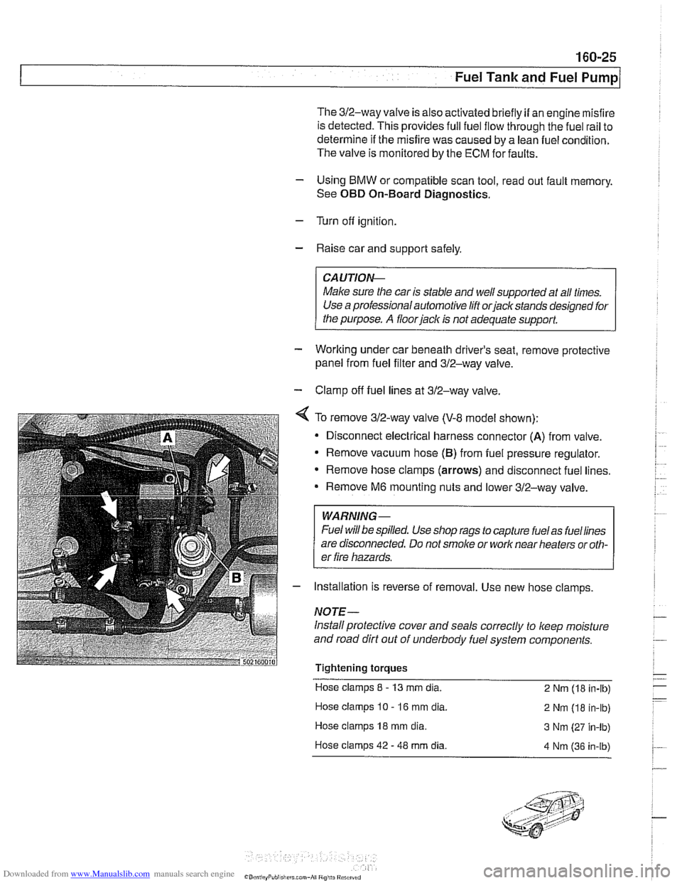
4 To remove 312-way valve (V-8 model shown):
Disconnect electrical harness connector
(A) from valve.
Remove vacuum hose
(B) from fuel pressure regulator.
* Remove hose clamps (arrows) and disconnect fuel lines.
Remove
M6 mounting nuts and lower 312-way valve.
WARNING-
Fuel will be spilled. Use shop rags to capture fuelas fuellines
are disconnected. Do not
smoke or work near heaters or oth-
er fire hazards.
- Installation is reverse of removal. Use new hose clamps
NOTE-
Install protective cover and seals correctly to keep moisture
and road dirt out of underbody fuel system components.
Tightening torques Hose clamps
8 - 13 mm dia.
2 Nm (18 in-lb)
Hose clamps
10 - 16 mm dia.
2 Nm (18 in-lb)
Hose clamps
18 mm dia. 3 Nm (27 in-lb)
Hose clamps 42
- 48 mm dia. 4 Nm 136 in-ib)
Page 511 of 1002
Downloaded from www.Manualslib.com manuals search engine
Radiator and Cooling System
Remove rubber trim strip between top of shroud and radiator.
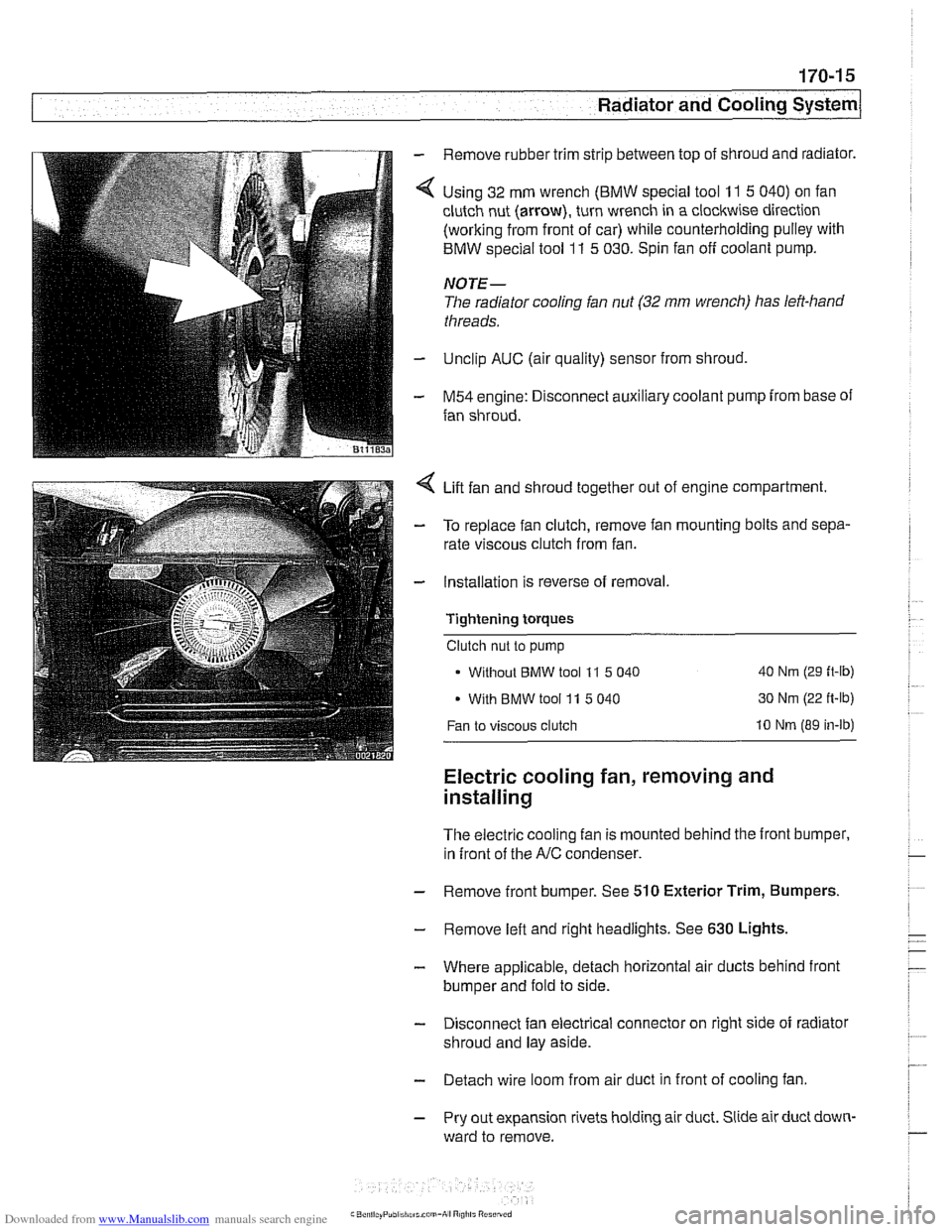
Using 32 mm wrench
(BMW special tool 11 5 040) on fan
clutch nut (arrow), turn wrench in a clockwise direction
(working from front of car) while counterholding pulley with
BMW special tool
11 5 030. Spin fan off coolant pump.
NOTE-
The radiator cooling fan nut (32 mm wrench) has left-hand
threads.
Unclip AUC (air quality) sensor from shroud,
M54 engine: Disconnect auxiliary coolant pump from base of
fan shroud.
Lift fan and shroud together out of engine compartment.
To replace fan clutch, remove fan mounting bolts and sepa-
rate viscous clutch from fan.
Installation is reverse of removal.
Tightening
torques
Clutch nut to pump
Without
BMW tool 11 5 040 40 Nm (29 ft-lb)
With BMW tool 11 5 040 30 Nm
(22 ft-lb)
Fan to viscous clutch 10 Nm (89 in-lb)
Electric cooling fan, removing and
installing
The electric cooling fan is mounted behind the front bumper,
in front of the
A/C condenser.
- Remove front bumper. See 510 Exterior Trim, Bumpers.
- Remove left and right headlights. See 630 Lights,
- Where applicable, detach horizontal air ducts behind front
bumper and fold to side.
- Disconnect fan electrical connector on right side of radiator
shroud and lay aside.
- Detach wire loom from air duct in front of cooling fan
- Pry out expansion rivets holding air duct. Slide air duct down-
ward to remove.
Page 512 of 1002
Downloaded from www.Manualslib.com manuals search engine
170-1 6
I Radiator and Cooling System
- Remove fan and fan shroud mounting fasteners. Slide fan
and fan shroud downward to remove.
- Reinstallation is reverse of removal.
Thermostat, removing and installing
(M52 engine)
The coolant thermostat is installed in a housing at the front of
the engine.
- Drain coolant from radiator and engine block. See Coolant,
draining and filling (6-cylinder models).
WARNING -
Allow the cooling system to cool before opening or draining
the system.
- Remove mechanical cooling fan and fan shroud. See Me-
chanical (viscous clutch) cooling fan, removing and in-
stalling.
- Disconnect coolant hoses from thermostat housing.
- Remove thermostat housing from front of engine.
- Remove thermostat. Note thermostat direction and orienta-
tion before removing.
- Installation is reverse of removal, noting the following:
- Use new O-ring and gasket(s) when installing thermostat
and housing.
NOTE-
Some thermostats have a direction arrow or vent hole near
the edge. Install the thermostat so that either the arrow or
hole are at the top.
Fill system with coolant as described in Coolant, draining
and filling (6-cylinder models).
CAUTION-
Be sure to reconnect ground wire@) at thermostat housing
mounting bolt, where applicable.
Page 513 of 1002
Downloaded from www.Manualslib.com manuals search engine
Radiator and Cooling systeml
Tightening torques
Block drain plug to block 25 Nm
(18
it-lb)
Coolant hose clamp (32 - 48 2.
5 Nm (22 in-lb)
mm hose diameter)
Radiator drain plug to radiator
2-3Nm(l8-27in-lb)
Thermostat housing to cylinder
head 10 Nm (89 in-lb)
I Coolant thermostat housing assmbly- - I
Thermostat, removing and installing
(M52 TU or M54 engine)
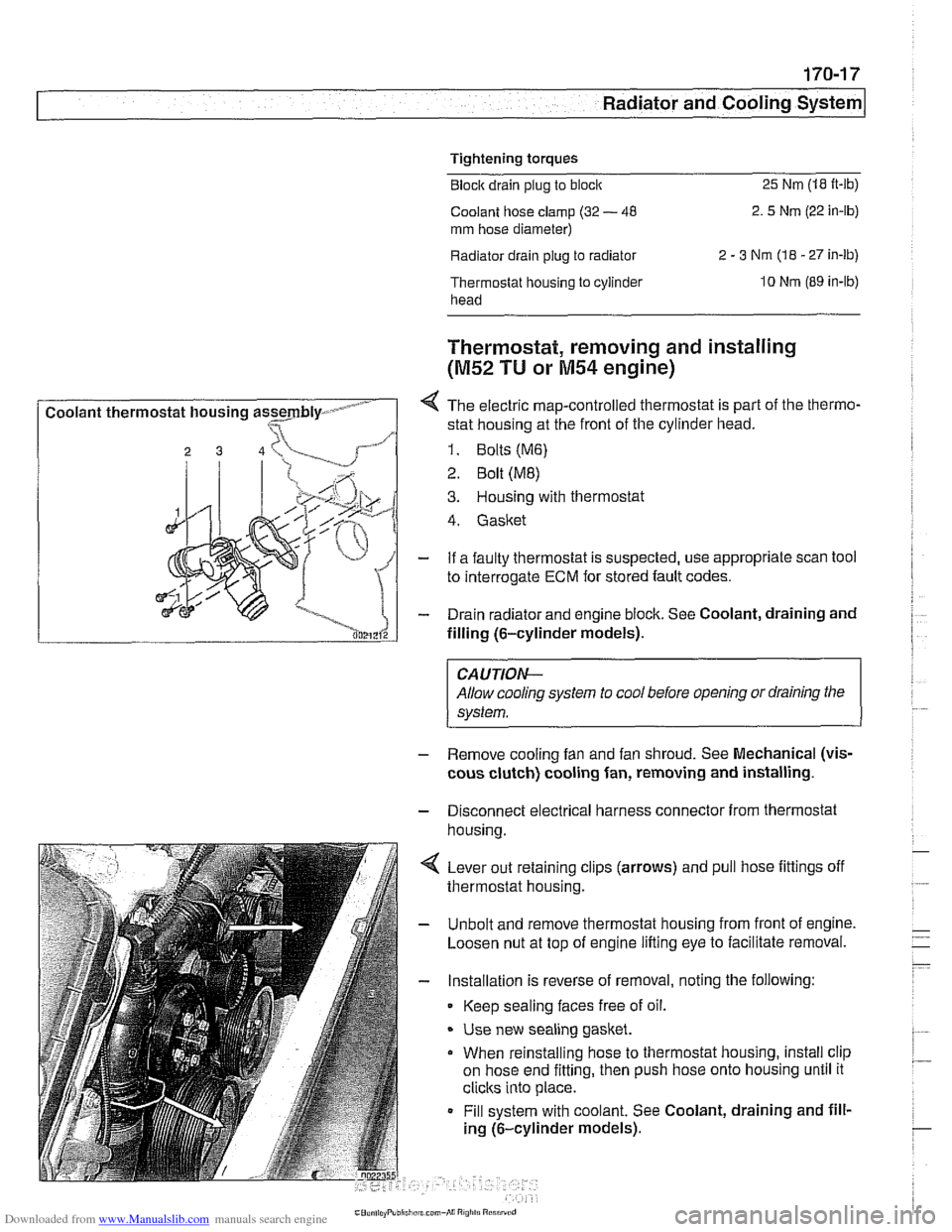
4 The electric map-controlled thermostat is part of the thermo-
stat housing at the front of the cylinder head.
1. Bolts (M6)
2 Bolt (ME)
3. Housing with thermostat
4. Gasket
- If a faulty thermostat is suspected, use appropriate scan tool
to interrogate
ECM for stored fault codes.
- Drain radiator and engine block. See Coolant, draining and
filling (6-cylinder models).
CAUTION-
Allow cooling system to cool before opening or draining the
system.
- Remove cooling fan and fan shroud. See Mechanical (vis-
cous clutch) cooling fan, removing and installing.
- Disconnect electrical harness connector from thermostat
housina.
4 Lever out retaining clips (arrows) and pull hose fittings off
thermostat housing.
- Unbolt and remove thermostat housing from front of engine.
Loosen nut at top of engine lifting eye to facilitate removal.
- Installation is reverse of removal, noting the following:
Keep sealing faces free of oil.
* Use new sealing gasket.
When reinstalling hose to thermostat housing, install clip
on hose end fitting, then push hose onto housing until it
clicks into place.
Fill system with coolant. See Coolant, draining and fill-
ing (6-cylinder models).
Page 515 of 1002
Downloaded from www.Manualslib.com manuals search engine
170-1 9
Radiator and Cooling System
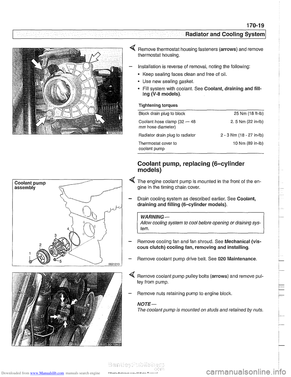
Coolant pump Remove thermostat housing fasteners
(arrows) and remove
thermostat housing.
Installation is reverse of removal, noting the following:
- Keep sealing faces clean and free of oil.
Use new sealing gasket.
Fill system with coolant. See Coolant, draining and fill-
ing
(V-8 models).
Tightening torques
Block drain plug to block 25 Nm (18 it-lb)
Coolant hose clamp (32
- 48 2. 5 Nm (22 in-lb)
mm hose diameter)
Radiator drain plug to radiator 2
- 3 Nm (18 - 27 In-lb)
Thermostat cover to
coolant pump 10 Nm (89 in-lb)
Coolant pump, replacing (6-cylinder
models)
< The engine coolant pump is mounted in the front of the en-
gine in the timing chain cover.
- Drain cooling system as described earlier. See Coolant,
draining and filling (6-cylinder models).
WARNING-
Allow cooling system to cool before opening or draining sys-
tem.
- Remove cooling fan and fan shroud. See Mechanical (vis-
cous clutch) cooling fan, removing and installing.
- Remove coolant pump drive belt. See 020 Maintenance.
4 Remove coolant pump pulley bolts (arrows) and remove pul-
ley from pump.
- Remove nuts retaining pump to engine block.
NOTE-
The coolant pump is mounted on studs and retained by nuts.
Page 516 of 1002
Downloaded from www.Manualslib.com manuals search engine
.," --
Radiator and Cooling System --- 1
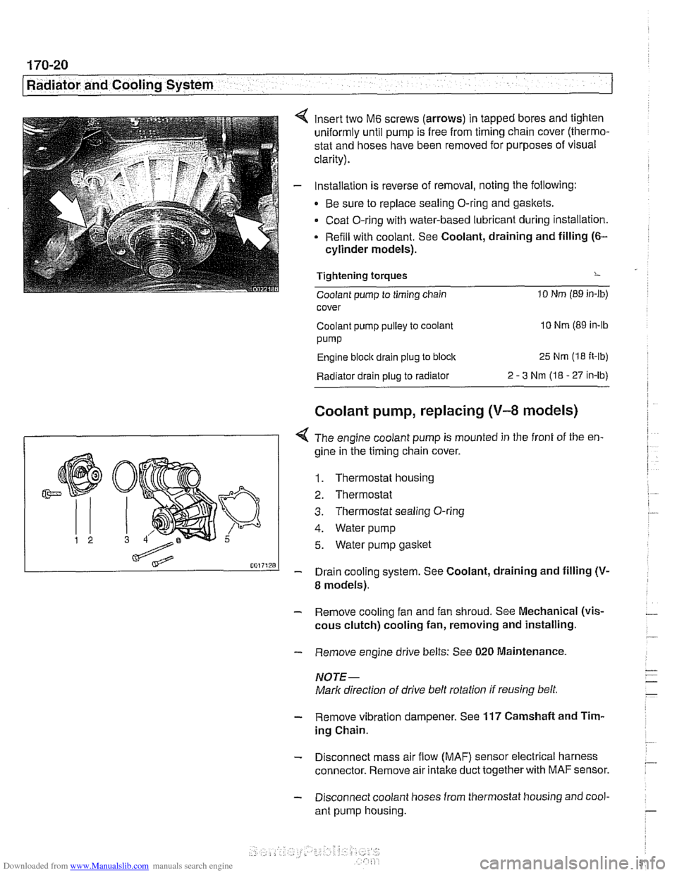
insert two M6 screws (arrows) in tapped bores and tighten
uniformly until pump is free from timing chain cover (thermo-
stat and hoses have been removed for purposes of visual
clarity).
Installation is reverse of removal, noting the following:
Be sure to replace sealing O-ring and gaskets.
Coat O-ring with water-based lubricant during installation.
Refill with coolant. See Coolant, draining and filling
(6-
cylinder models).
Tightening torques
-
Coolant pump to timing chain 10 Nm (89 in-lb)
cover
Coolant pump pulley to coolant
10 Nm (89 in-lb
pump
Engine block drain plug to block 25 Nm (1 8 It-lb)
Radiator drain plug to radiator 2 - 3 Nm (I8 - 27 in-lb)
Coolant pump, replacing (V-8 models)
I 1 < The engine coolant pump is mounted in the front of the en-
gine in ;he timing chain cover.
1. Thermostat housing
2. Thermostat
3. Thermostat sealing O-ring
4. Water pump
5. Water pump gasket
- Drain cooling system. See Coolant, draining and filling (V-
8 models).
- Remove cooling fan and fan shroud. See Mechanical (vis-
cous clutch) cooling fan, removing and installing.
- Remove engine drive belts: See 020 Maintenance.
NOTE-
Mark direction of drive belt rotation if reusing belt,
- Remove vibration dampener. See 117 Camshaft and Tim-
ing Chain.
- Disconnect mass air flow (MAF) sensor electrical harness
connector. Remove air intake duct together with
MAF sensor.
- Disconnect coolant hoses from thermostat housing and cool-
ant pump housing.
Page 517 of 1002
Downloaded from www.Manualslib.com manuals search engine
Radiator and Coolina ~vsteml
- Disconnect thermostat and cooling system temperature sen-
sor plug connectors.
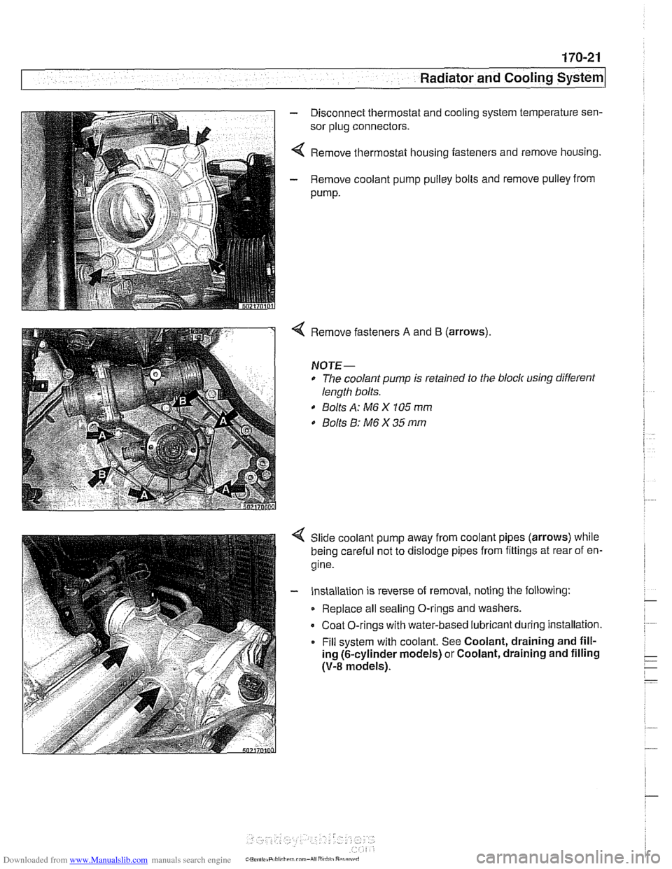
4 Remove thermostat housing fasteners and remove housing.
- Remove coolant pump pulley bolts and remove pulley from
pump.
Remove fasteners A and B (arrows).
NOTE-
* The coolant pump is retained to the block using different
length bolts.
0 Bolts A: M6 X 105 mm
0 Bolts 8: M6 X 35 mm
Slide coolant pump away from coolant pipes (arrows) while
being careful not to dislodge pipes from fittings at rear of en-
gine.
- Installation is reverse of removal, noting the following:
Replace all sealing O-rings and washers.
Coat O-rings with water-based lubricant during installation.
Fill system with coolant. See Coolant, draining and fill-
ing (6-cylinder models) or Coolant, draining and filling
(V-8 models).
Page 520 of 1002
Downloaded from www.Manualslib.com manuals search engine
--
Radiator and Cooling System 1
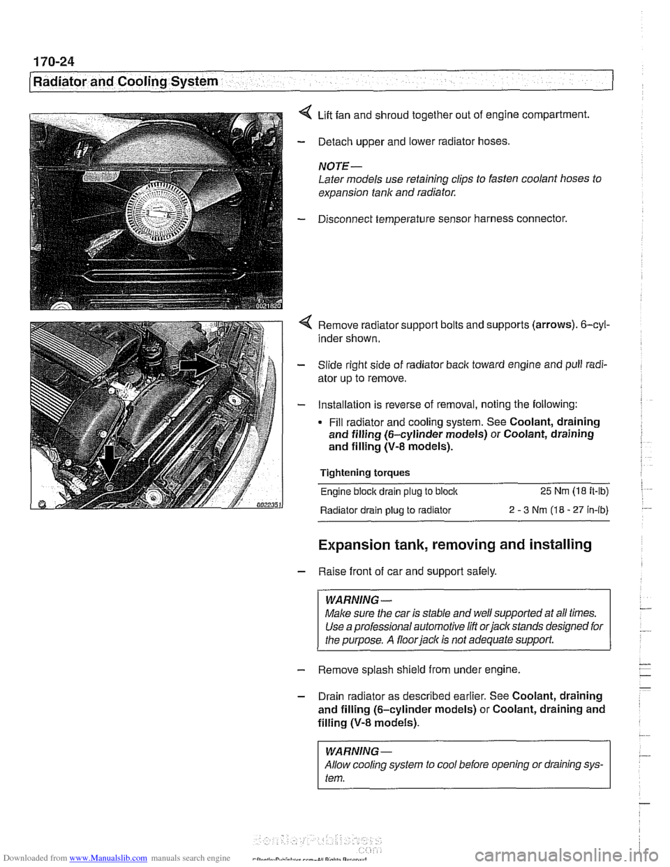
4 Lift fan and shroud together out of engine compartment.
- Detach upper and lower radiator hoses.
NOTE -
Later models use retaining clips to fasten coolant hoses to
expansion tank and radiator.
- Disconnect temperature sensor harness connector.
4 Remove radiator support bolts and supports (arrows). 6-cyl-
inder shown.
- Slide right side of radiator back toward engine and pull radi-
ator up to remove.
- Installation is reverse of removal, noting the following:
Fill radiator and cooling system. See Coolant, draining
and filling (6-cylinder models) or Coolant, draining
and filling (V-8 models).
Tightening torques
Engine block drain
plug to block 25 Nm (18 it-lb)
Radiator drain plug
to radiator 2 - 3 Nm (18 - 27 in-ib)
Expansion tank, removing and installing
- Raise front of car and support safely.
WARNING -
Make sure the car is stable and well supported at all times.
Use a professional automotive
/iff orjacltstands designed for
the purpose. A
floorjacl~ is not adequate support.
- Remove splash shield from under engine.
- Drain radiator as described earlier. See Coolant, draining
and filling (6-cylinder models) or Coolant, draining and
filling
(V-8 models).
I WARNING-
Allow cooling system to cool before opening or draining sys-
I tem.
Page 521 of 1002
![BMW 528i 1999 E39 Repair Manual Downloaded from www.Manualslib.com manuals search engine
170-25
Radiator and Cooling system]
< Disconnect expansion tank:
Remove expansion tank bleed screw and support clip
(A)
Loosen hose c BMW 528i 1999 E39 Repair Manual Downloaded from www.Manualslib.com manuals search engine
170-25
Radiator and Cooling system]
< Disconnect expansion tank:
Remove expansion tank bleed screw and support clip
(A)
Loosen hose c](/img/1/2822/w960_2822-520.png)
Downloaded from www.Manualslib.com manuals search engine
170-25
Radiator and Cooling system]
< Disconnect expansion tank:
Remove expansion tank bleed screw and support clip
(A)
Loosen hose clamp (6) and disconnect coolant hose from
expansion tank.
Disconnect harness connector from coolant level sensor
(C).
Push top of expansion tank toward engine and disconnect
bleed hose.
Lift expansion
tank to free it from lower mounts, then lift
straight up to remove.
- Installation is reverse of removal, noting the following:
Fill radiator and cooling system as described earlier. See
Coolant, draining and filling (6-cylinder models) or
Coolant, draining and filling
(V-8 models).