BMW 528i 2001 E39 Workshop Manual
Manufacturer: BMW, Model Year: 2001, Model line: 528i, Model: BMW 528i 2001 E39Pages: 1002
Page 151 of 1002
Downloaded from www.Manualslib.com manuals search engine
Cylinder Head Removal and Installation /
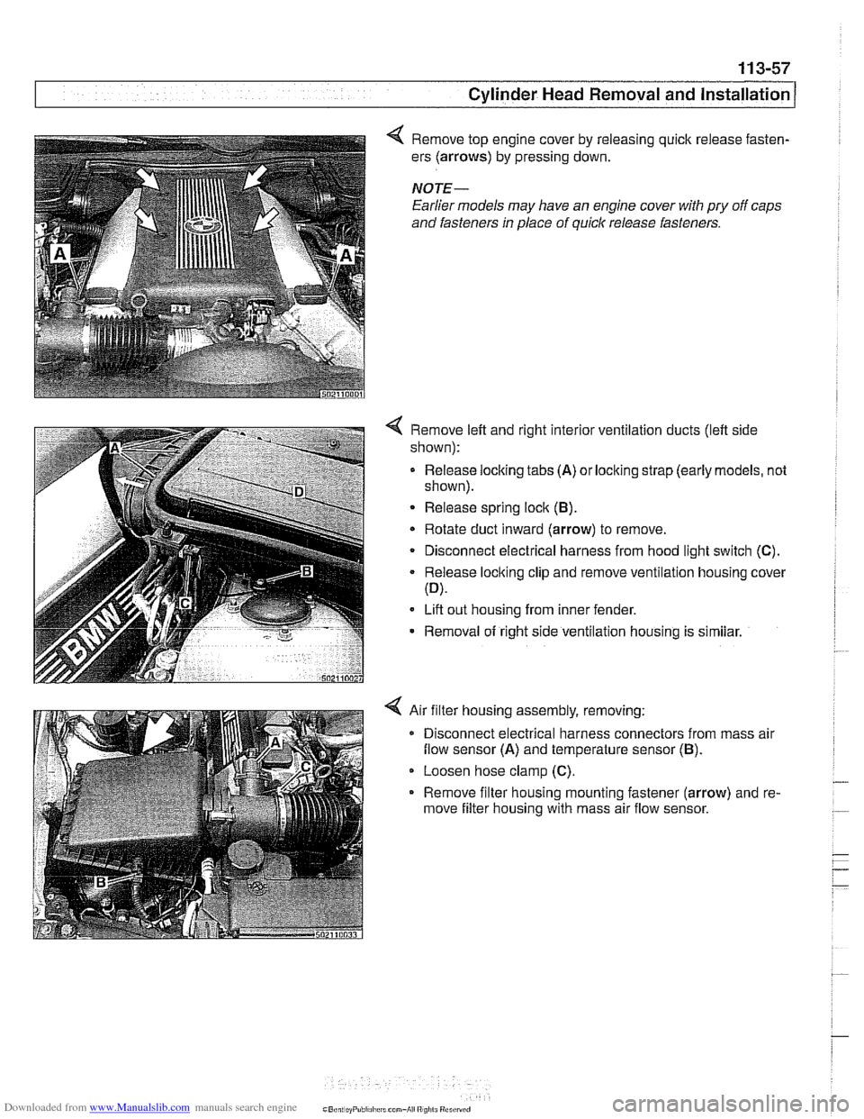
4 Remove top engine cover by releasing quick release fasten-
ers (arrows) by pressing down.
NOTE-
Earlier models may have an engine cover with pry off caps
and fasteners
In place of quick release fasteners.
4 Remove left and right interior ventilation ducts (left side
shown):
- Release locking tabs (A) or locking strap (early models, not
shown).
Release spring lock (B).
* Rotate duct inward (arrow) to remove.
Disconnect electrical harness from hood light switch (C).
Release locking clip and remove ventilation housing cover
(D).
Lift out housing from inner fender.
- Removal of right side ventilation housing is similar.
4 Air filter housing assembly, removing:
Disconnect electrical harness connectors from mass air
flow sensor (A) and temperature sensor (B).
Loosen hose clamp (C).
Remove filter housing mounting fastener (arrow) and re-
move filter housing with mass air flow sensor.
Page 152 of 1002
Downloaded from www.Manualslib.com manuals search engine
Cylinder Head Removal and Installation
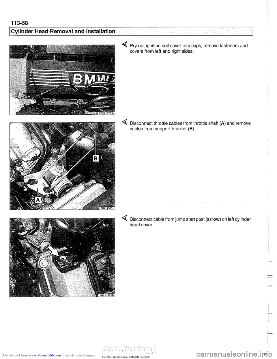
Pry out ignition coil cover trim caps,
covers from lefl and right sides. remove fasteners
and
< Disconnect throttle cables from throttle shafl (A) and remove
cables from support bracket
(B).
< Disconnect cable from jump start post (arrow) on left cylinder
head cover.
Page 153 of 1002
Downloaded from www.Manualslib.com manuals search engine
- .-
.. Cylinder Head Removal and Installation I -
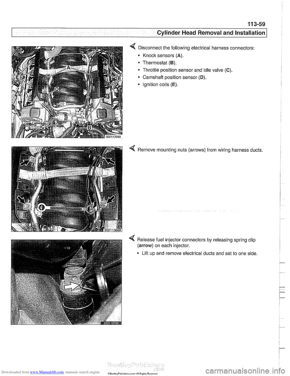
< Disconnect the following electrical harness connectors:
Knock sensors
(A).
Thermostat (6).
Throttle position sensor and idle valve (C).
Camshaft position sensor (D).
Ignition coils (E).
< Remove mounting nuts (arrows) from wiring harness ducts.
4 Release fuel injector connectors by releasing spring clip
(arrow) on each injector.
Lift up and remove electrical ducts and set to one side
Page 154 of 1002
Downloaded from www.Manualslib.com manuals search engine
1 13-60
Cylinder Head Removal and Installation
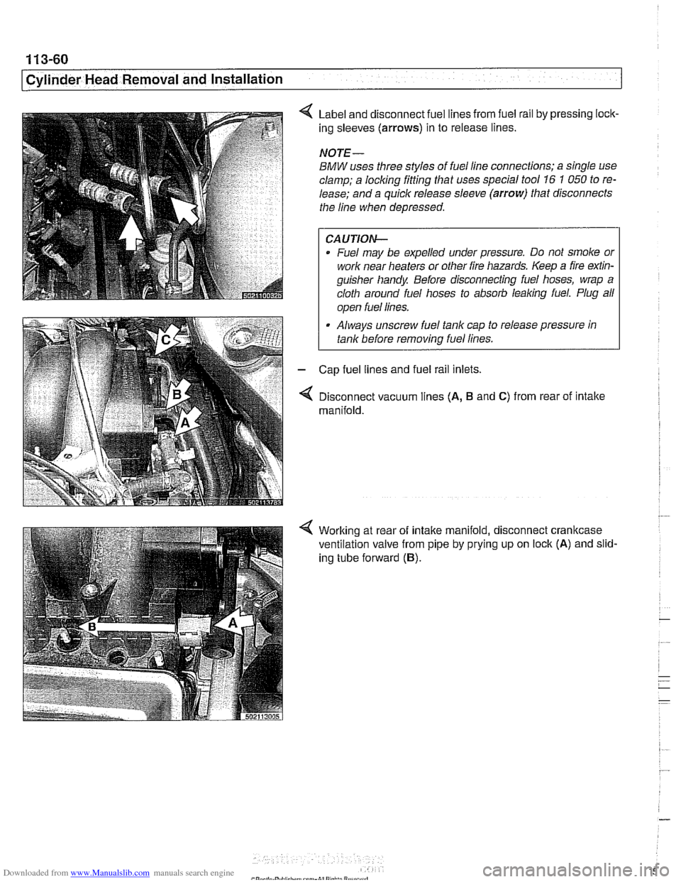
Label and disconnect fuel lines from fuel rail by pressing lock-
ing sleeves
(arrows) in to release lines.
NOTE-
BMW uses three styles of fuel line connections; a single use
clamp; a locking fitting that uses special tool
16 1 050 to re-
lease; and a quick release sleeve
(arrow) that disconnects
the line when depressed.
CAUTION-
Fuel may be expelled under pressure. Do not smoke or
work near heaters or other fire hazards. Keep a fire
exfin-
guisher handy Before disconnecting fuel hoses, wrap a
cloth around fuel hoses to absorb
leaking fuel. Plug all
I ooen fuel lines. I
Always unscrew fuel tank cap to release pressure in
tank before
removinq fuel lines.
Cap fuel lines and fuel rail inlets.
Disconnect vacuum lines
(A, B and C) from rear of intake
manifold.
Working at rear of intake manifold, disconnect crankcase
ventilation valve from pipe by prying up on lock
(A) and slid-
ing tube forward
(B).
Page 155 of 1002
Downloaded from www.Manualslib.com manuals search engine
11 3-61
Cylinder Head Removal and installation I
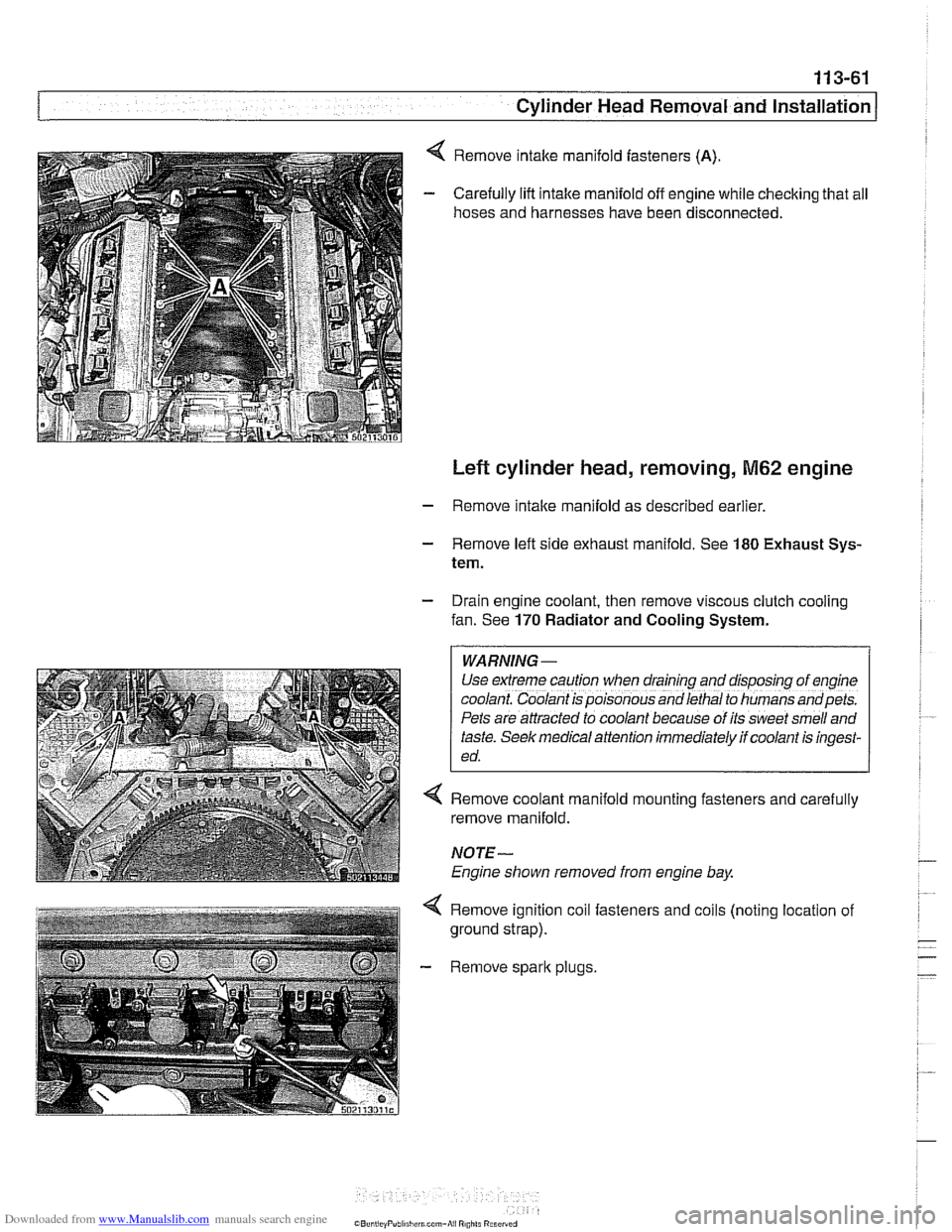
Remove intake manifold fasteners (A).
Carefully lift intake manifold off engine while checking that all
hoses and harnesses have been disconnected.
Left cylinder head, removing, M62 engine
- Remove intake manifold as described earlier
- Remove left side exhaust manifold. See 180 Exhaust Sys-
tem.
- Drain engine coolant, then remove viscous clutch cooling
fan. See
170 Radiator and Cooling System.
WARNING -
Use extreme caution when draining and disposfng of eng~ne
coolant. Coolant is poisonous and lethal to humans andpets.
Pets are attracted to coolant because of its sweet smell and
taste.
Seek med~cal attention immediately if coolant is ingest-
ed.
4 Remove coolant manifold mounting fasteners and carefully
remove manifold.
NOTE-
Engine shown removed from engine bay
4 Remove ignition coil fasteners and coils (noting location of
ground strap).
- Remove spark plugs.
Page 156 of 1002
Downloaded from www.Manualslib.com manuals search engine
. .- --
[Cylinder ~ead Removal and Installation
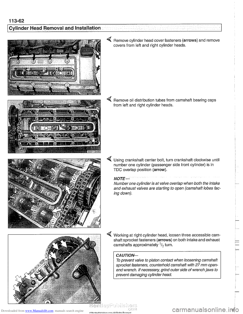
4 Remove cylinder head cover fasteners (arrows) and remove
covers from left and right cylinder heads.
4 Remove oil distribution tubes from camshaft bearing caps
from left and right cylinder heads.
4 Using crankshaft center bolt, turn crankshaft clockwise until
number one cylinder (passenger side front cylinder) is in
TDC overlap position (arrow).
NO JE -
Number one cylinder is at valve overlap when both the intake
and exhaust valves are starting to open (camshaft lobes fac-
ing down).
4 Working at right cylinder head, loosen three accessible cam-
shaft sprocltet fasteners (arrows) on both intake and exhaust
camshafts approximately
'I2 turn.
To prevent valve to piston contact when loosening camshaft
sprocket fasteners, counterhold camshaft with
27 mm open-
end wrench.
If necessary, grind outerside of wrench jaws to
prevent damaging cylinder head.
Page 157 of 1002
Downloaded from www.Manualslib.com manuals search engine
.- --
Cylinder Head Removal and Installation I
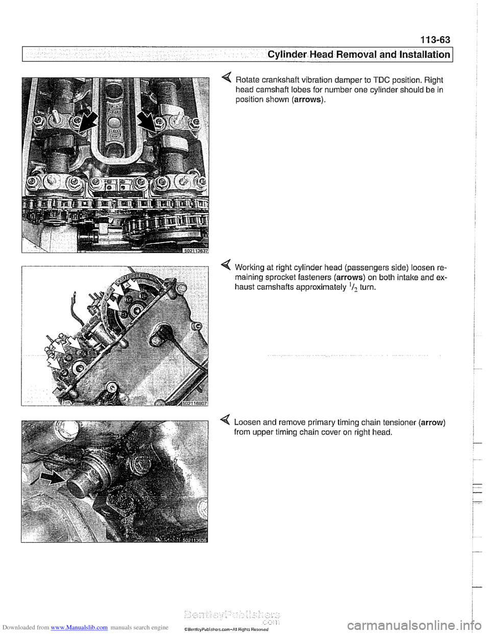
4 Rotate crankshaft vibration damper to TDC position. Right
head camshaft lobes for number one cylinder should be in
position shown (arrows).
Working at right cylinder head (passengers side) loosen re-
maining
sprocltet fasteners (arrows) on both intake and ex-
haust camshafts approximately
'/? turn.
4 Loosen and remove primary timing chain tensioner (arrow)
from upper timing chain cover on right head.
Page 158 of 1002
Downloaded from www.Manualslib.com manuals search engine
1 13-64
Cylinder Head Removal and Installation
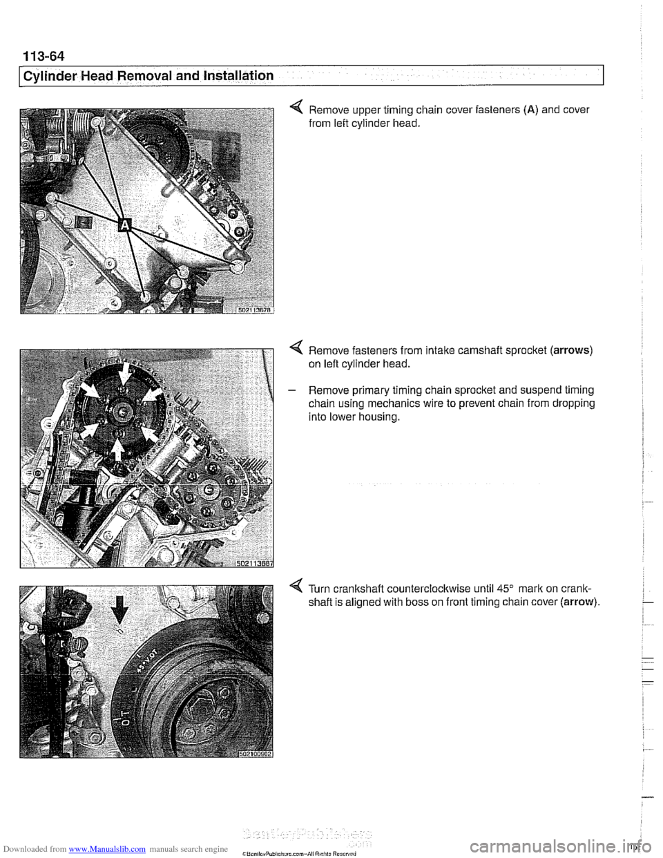
< Remove upper timing chain cover fasteners (A) and cover
from left cylinder head.
4 Remove fasteners from intake camshaft sprocket (arrows)
on left cylinder head.
- Remove primary timing chain sprocket and suspend timing
chain using mechanics wire to prevent chain from dropping
into lower housing.
Turn crankshaft counterclockwise until
45" mark on crank-
shaft is aligned with boss on front timing chain cover
(arrow).
Page 159 of 1002
Downloaded from www.Manualslib.com manuals search engine
1 13-65
Cylinder Head Removal and Installation /
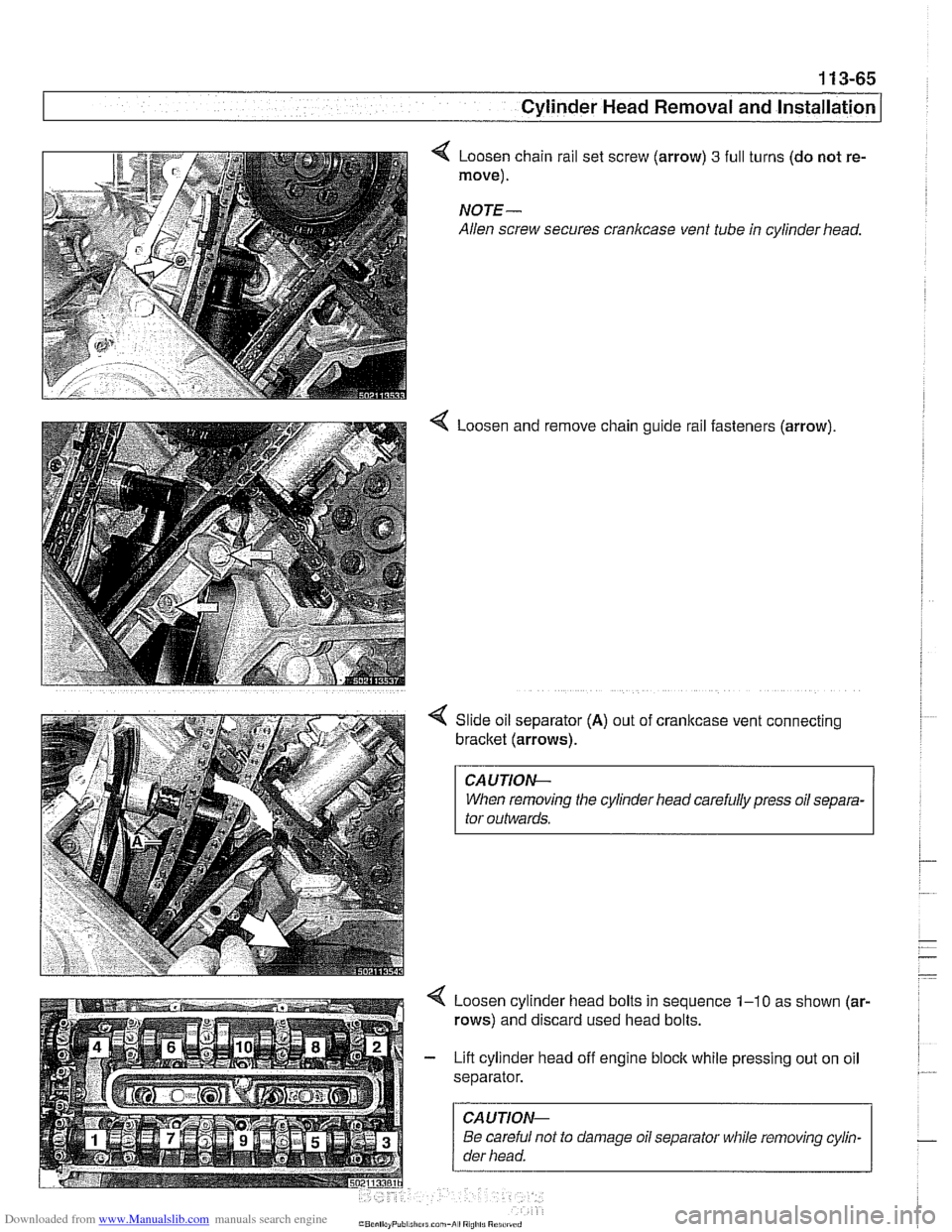
Loosen chain rail set screw (arrow) 3 full
move).
NOTE-
Allen screw secures crankcase vent tube
4 Loosen and turns
(do not re-
in cylinder head.
remove chain guide rail fasteners (arrow).
Slide oil separator
(A) out of cranltcase vent connecting
bracket (arrows).
CAUTIOI\C
When removing the cylinder head carefully press oil separa-
tor outwards.
Loosen cylinder head bolts in sequence
1-10 as shown (ar-
rows) and discard used head bolts.
Lift cylinder head off engine block while pressing out on oil
separator.
CAUTIOI\C
Be careful not to damage oil separator while removing cylin-
der head.
Page 160 of 1002
Downloaded from www.Manualslib.com manuals search engine
. .- --
I Cylinder Head Removal and Installation
- Evaluate cylinder head as described in 116 Cylinder head
and valvetrain.
Left cylinder head, installing, M62 engine
- Clean cylinder head and block sealing surfaces of gasket
debris, making sure no debris drops into coolant or oil pas-
sages.
- Clean cylinder head bolt holes and check condition of
threads.
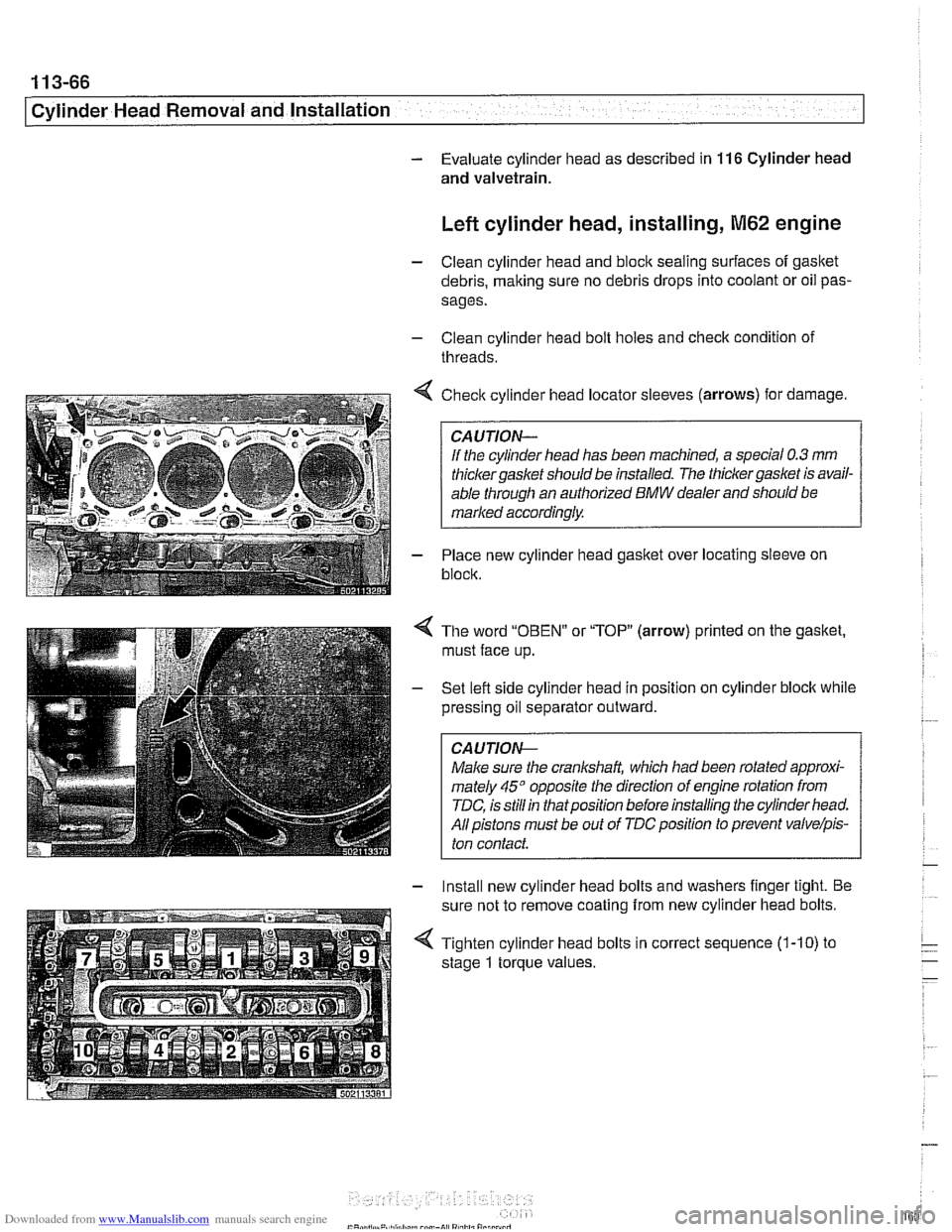
< Check cylinder head locator sleeves (arrows) for damage.
If the cylinder head has been machined, a special
0.3 mm
thicker gasket should be installed. The thicker gasket is avail-
able through an authorized
BMW dealer and should be
marked accordingly.
- Place new cylinder head gasket over locating sleeve on
block.
The word
"OBEN" or "TOP" (arrow) printed on the gasket,
must face up.
Set lefl side cylinder head in position on cylinder block while
pressing oil separator outward.
CAUJION-
Male sure the crankshaft, which had been rotated approxi-
mately
45" opposite the direction of engine rotation from
TDC, is still in thatposition before installing the cylinder head.
All pistons must be out of
TDCposition to prevent valvelpis-
ton contact.
- Install new cylinder head bolts and washers finger tight. Be
sure not to remove coating from new cylinder head bolts.
4 Tighten cylinder head bolts in correct sequence (1-10) to
stage
1 torque values.