park BMW 528I 2012 Owner's Manual
[x] Cancel search | Manufacturer: BMW, Model Year: 2012, Model line: 528I, Model: BMW 528I 2012Pages: 335, PDF Size: 13.16 MB
Page 116 of 335
DistanceSelecting a distance
Adjust the distance according to the traffic
and weather conditions; otherwise, there is the
danger of an accident occurring. Maintain the
prescribed safety distance.◀
Reduce distance Press the button repeatedly until the
desired distance is set.
The selected distance, refer to page 117, is dis‐
played in the instrument cluster.
Increase distance Press the button repeatedly until the
desired distance is set.
The selected distance, refer to page 117, is dis‐
played in the instrument cluster.
Calling up the desired speed and
distance
While driving Press the button with the system
switched on.
In the following cases, the stored speed value is
deleted and cannot be called up again:▷When the system is switched off.▷When the ignition is switched off.
While standing
Before leaving the vehicle, secure it
against rolling.
Before leaving the vehicle with the engine run‐
ning, engage position P of the automatic trans‐
mission and apply the parking brake. Otherwise,
the vehicle may begin to roll.◀
The system brought the vehicle to a complete
standstill.
▷Green mark in the speedometer during a
brief idle phase:
The vehicle ahead of you drives away while
the mark is green: your vehicle accelerates
without anything having to be done.▷Switch to orange of the mark in the speed‐
ometer after approx. 2 sec.:
The vehicle ahead of you drives away, while
the mark is orange: in order to accelerate,
briefly press the gas pedal or press the RES
button or SET button.
Rolling bars in the distance indicator mean that
the vehicle ahead of you has driven off.
You actively braked your vehicle to a halt by
pressing on the brake pedal and it is standing
behind another vehicle:
1. Press the button to call up a stored
desired speed.2.Release the brake pedal.3.Press on the accelerator briefly, or press the
RES button or the rocker switch when the
vehicle ahead of you drives away.
Displays in the instrument cluster
Desired speed
▷The marking lights up in
green: the system is active.▷The marking lights up in or‐
ange: the system has been
interrupted.▷The marking does not light up: the system is
switched off.
Brief status display
Selected desired speed.
If --- appears briefly on the display for Check
Control messages, it is possible that the system
Seite 116ControlsDriving comfort116
Online Edition for Part no. 01 40 2 607 879 - 09 11 490
Page 119 of 335
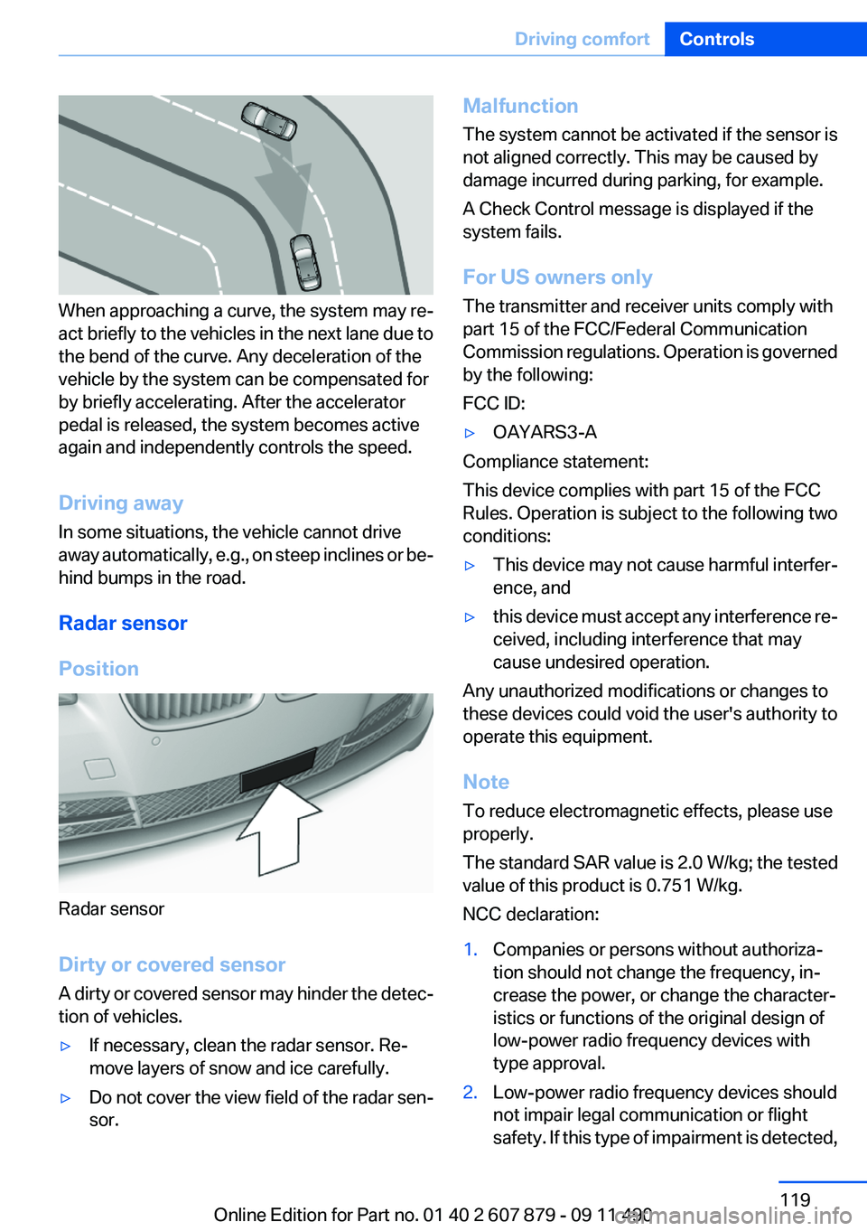
When approaching a curve, the system may re‐
act briefly to the vehicles in the next lane due to
the bend of the curve. Any deceleration of the
vehicle by the system can be compensated for
by briefly accelerating. After the accelerator
pedal is released, the system becomes active
again and independently controls the speed.
Driving away
In some situations, the vehicle cannot drive
away automatically, e.g., on steep inclines or be‐
hind bumps in the road.
Radar sensor
Position
Radar sensor
Dirty or covered sensor
A dirty or covered sensor may hinder the detec‐
tion of vehicles.
▷If necessary, clean the radar sensor. Re‐
move layers of snow and ice carefully.▷Do not cover the view field of the radar sen‐
sor.Malfunction
The system cannot be activated if the sensor is
not aligned correctly. This may be caused by
damage incurred during parking, for example.
A Check Control message is displayed if the
system fails.
For US owners only
The transmitter and receiver units comply with
part 15 of the FCC/Federal Communication
Commission regulations. Operation is governed
by the following:
FCC ID:▷OAYARS3-A
Compliance statement:
This device complies with part 15 of the FCC
Rules. Operation is subject to the following two
conditions:
▷This device may not cause harmful interfer‐
ence, and▷this device must accept any interference re‐
ceived, including interference that may
cause undesired operation.
Any unauthorized modifications or changes to
these devices could void the user's authority to
operate this equipment.
Note
To reduce electromagnetic effects, please use
properly.
The standard SAR value is 2.0 W/kg; the tested
value of this product is 0.751 W/kg.
NCC declaration:
1.Companies or persons without authoriza‐
tion should not change the frequency, in‐
crease the power, or change the character‐
istics or functions of the original design of
low-power radio frequency devices with
type approval.2.Low-power radio frequency devices should
not impair legal communication or flight
safety. If this type of impairment is detected,Seite 119Driving comfortControls119
Online Edition for Part no. 01 40 2 607 879 - 09 11 490
Page 123 of 335
If active, the displayed speed is stored and the
vehicle reaches the stored speed if the road is
clear.▷Each time the rocker switch is pressed to the
point of resistance, the desired speed in‐
creases or decreases by approx. 1 mph/
1 km/h.▷Each time the rocker switch is pressed past
the point of resistance, the desired speed
increases or decreases by a maximum of
5 mph/10 km/h.▷Pressing the rocker switch to the resistance
point and holding it accelerates or deceler‐
ates the vehicle without requiring pressure
on the accelerator. After the rocker switch is
released, the vehicle maintains its final
speed. Pressing the switch beyond the re‐
sistance point causes the vehicle to accel‐
erate more rapidly.
Resuming the desired speed
Press the button.
The stored speed is reached and maintained.
Displays in the instrument cluster
Indicator lamp Depending on how the vehicle is equip‐
ped, the indicator lamp in the instrument
cluster indicates whether the system is
switched on.
Desired speed
▷The marking lights up in
green: the system is active.▷The marking lights up in or‐
ange: the system has been
interrupted.▷The marking does not light up: the system is
switched off.Brief status display
Selected desired speed.
If --- appears briefly on the display for Check
Control messages, it is possible that the system
requirements for operation are currently not
met.
PDC Park Distance Control
The concept
In addition to the PDC Park Distance Control, the
backup camera, refer to page 126, can be
switched on.
PDC supports you when parking. Objects that
you are approaching slowly in front of or behind
your vehicle are indicated with:▷Signal tones.▷Visual display.
Measurement
Measurements are made by ultrasound sensors
in the bumpers.
The range is approx. 6 ft/2 m.
An acoustic warning is first given:
▷By the front sensors and the two rear corner
sensors at approx. 24 in/60 cm.▷By the rear middle sensors at approx. 5 ft/
1.50 m.
System limits
Check the traffic situation as well
PDC cannot serve as a substitute for the
driver's personal judgment of the traffic situa‐
tion. Check the traffic situation around the vehi‐
cle with your own eyes. Otherwise, an accident
could result from road users or objects located
outside of the PDC detection range.
Seite 123Driving comfortControls123
Online Edition for Part no. 01 40 2 607 879 - 09 11 490
Page 125 of 335
The intermittent tone is interrupted after approx.
3 seconds:▷If the vehicle stops in front of an object that
is detected by only one of the corner sen‐
sors.▷If moving parallel to a wall.
The signal tone is switched off:
▷When the vehicle moves away from an ob‐
ject by more than approx. 4 in/10 cm.▷When transmission position P is engaged.
Volume
You can set the volume of the PDC signal tone,
refer to page 191.
The setting is stored for the remote control cur‐
rently in use.
Visual warning
The approach of the vehicle to an object can be
shown on the Control Display. Objects that are
farther away are displayed on the Control Dis‐
play before a signal tone sounds.
A display appears as soon as Park Distance
Control (PDC) is activated.
If the backup camera image was selected last, it
again appears on the display. To switch to PDC:
1. "Rear view camera" Select the symbol
on the Control Display.2.Press the controller.
The setting is stored for the remote control cur‐
rently in use.
Zoom view
On the left part of the display screen, the vehicle
is shown enlarged.
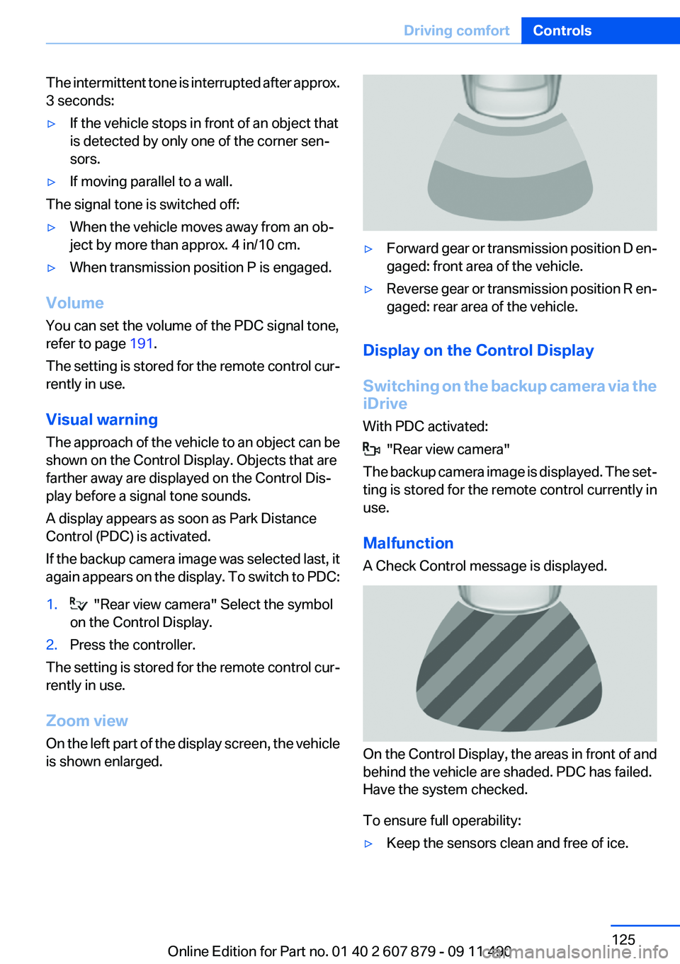
▷Forward gear or transmission position D en‐
gaged: front area of the vehicle.▷Reverse gear or transmission position R en‐
gaged: rear area of the vehicle.
Display on the Control Display
Switching on the backup camera via the
iDrive
With PDC activated:
"Rear view camera"
The backup camera image is displayed. The set‐
ting is stored for the remote control currently in
use.
Malfunction
A Check Control message is displayed.
On the Control Display, the areas in front of and
behind the vehicle are shaded. PDC has failed.
Have the system checked.
To ensure full operability:
▷Keep the sensors clean and free of ice.Seite 125Driving comfortControls125
Online Edition for Part no. 01 40 2 607 879 - 09 11 490
Page 126 of 335
▷When using a pressure washer, keep the
sprayer moving and maintain a distance of
at least 12 in/30 cm from the sensors.
Surround View
The concept
Surround View includes the following systems:
▷Backup camera, refer to page 126.▷Side View, refer to page 130.▷Top View, refer to page 128.
It assists the driver when parking, maneuvering
and on blind driveways and intersections.
Backup camera
The concept
The backup camera provides assistance in park‐
ing and maneuvering backwards. The area be‐
hind the vehicle is shown on the Control Display.
System limits Check the traffic situation as well
Check the traffic situation around the ve‐
hicle with your own eyes. Otherwise, an accident
could result from road users or objects located
outside the picture area of the backup camera. ◀
Detection of objects
High, protruding objects such as ledges
may not be detected by the backup camera.◀
Switching on automatically
Select transmission position R with the engine
running.
The backup camera image is displayed if the
system was switched on via the iDrive.
Automatic deactivation during forward
travel
The system switches off when a certain driving
distance or speed is exceeded.
Switch the system back on if necessary.
Switching on/off manually
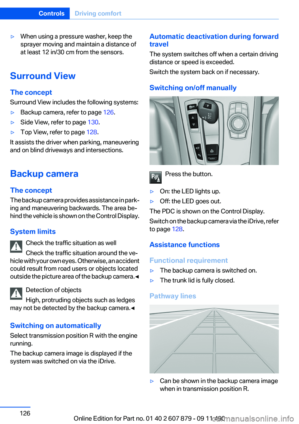
Press the button.
▷On: the LED lights up.▷Off: the LED goes out.
The PDC is shown on the Control Display.
Switch on the backup camera via the iDrive, refer
to page 128.
Assistance functions
Functional requirement
▷The backup camera is switched on.▷The trunk lid is fully closed.
Pathway lines
▷Can be shown in the backup camera image
when in transmission position R.Seite 126ControlsDriving comfort126
Online Edition for Part no. 01 40 2 607 879 - 09 11 490
Page 127 of 335
▷Help you to estimate the space required
when parking and maneuvering on level
roads.▷Are dependent on the current steering angle
and are continuously adjusted to the steer‐
ing wheel movements.
Show the parking aid lines, refer to page 127.
Turning circle lines
▷Can be shown in the backup camera image.▷Show the course of the smallest possible
turning circle on a level road.▷Only one turning circle line is displayed
when the steering wheel is turned.
Show the parking aid lines, refer to page 127.
Parking using pathway and turning
circle lines
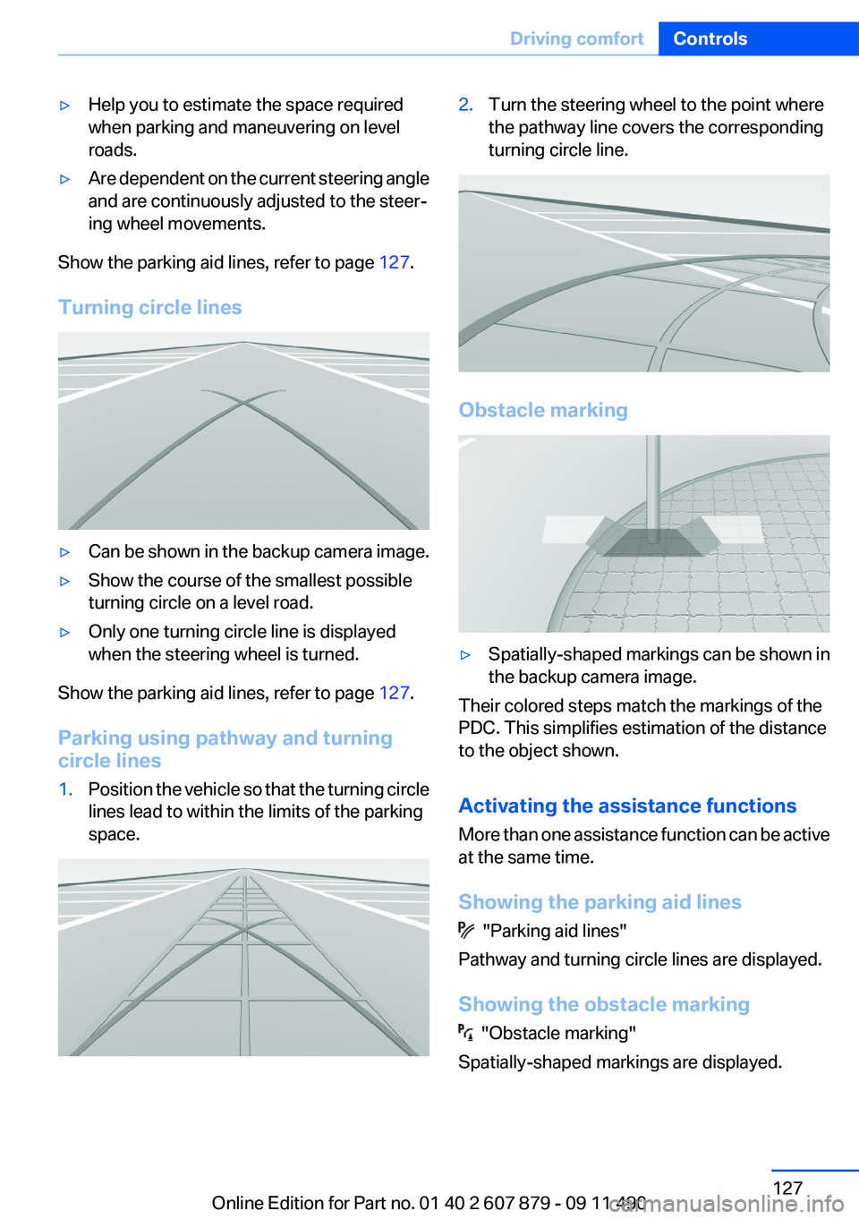
1.Position the vehicle so that the turning circle
lines lead to within the limits of the parking
space.2.Turn the steering wheel to the point where
the pathway line covers the corresponding
turning circle line.
Obstacle marking
▷Spatially-shaped markings can be shown in
the backup camera image.
Their colored steps match the markings of the
PDC. This simplifies estimation of the distance
to the object shown.
Activating the assistance functions
More than one assistance function can be active
at the same time.
Showing the parking aid lines
"Parking aid lines"
Pathway and turning circle lines are displayed.
Showing the obstacle marking
"Obstacle marking"
Spatially-shaped markings are displayed.
Seite 127Driving comfortControls127
Online Edition for Part no. 01 40 2 607 879 - 09 11 490
Page 128 of 335

Display on the Control Display
Switching on the backup camera via
iDrive
With PDC activated:
"Rear view camera"
The backup camera image is displayed. The set‐
ting is stored for the remote control currently in
use.
Brightness
With the backup camera switched on:
1. Select the symbol.2.Turn the controller until the desired setting
is reached and press the controller.
Contrast
With the backup camera switched on:
1. Select the symbol.2.Turn the controller until the desired setting
is reached and press the controller.
Camera
The camera lens is located in the handle of the
trunk lid. The image quality may be impaired by
dirt.
Clean the lens, refer to page 307.
Top View
The concept
Top View assists you in parking and maneuver‐
ing. The area around the doors and the road area
around the vehicle are shown on the Control
Display for this purpose.
Capturing the image
The image is captured by two cameras
integrated in the exterior mirrors and by the
backup camera.
The range equals:▷Approx. 7 ft/2 m to the side.▷approx. 7 ft/2 m to the rear.
In this way, obstacles up to the height of the ex‐
terior mirrors are detected early.
System limits
Top View cannot be used in the following situa‐
tions:
▷With a door open.▷With the trunk lid open.▷With an exterior mirror folded in.▷In poor light.
A Check Control message is displayed in some
of these situations.
Check the traffic situation as well
Check the traffic situation around the ve‐
hicle with your own eyes. Otherwise, an accident
could result from road users or objects located
outside the picture area of the cameras.◀
Switching on automatically
Select transmission position R with the engine
running.
The Top View and PDC images are displayed if
the system is switched on via iDrive.
Seite 128ControlsDriving comfort128
Online Edition for Part no. 01 40 2 607 879 - 09 11 490
Page 130 of 335
"Parking aid lines"
Turning circle and pathway lines are displayed.
Cameras
The objectives of the Top View cameras are lo‐
cated at the bottom of the exterior mirror hous‐
ings. The image quality may be impaired by dirt.
Clean the lens, refer to page 307.
Side View
The concept
Side View provides an early look at cross traffic
at blind driveways and intersections. Road users
concealed by obstacles to the left and right of
the vehicle can only be detected relatively late
from the driver's seat. To improve visibility, two
cameras in the front of the vehicle record the
traffic situation on each side.
System limits
The cameras capture a maximum range of
330 ft/100 m.
Display
The images from both cameras are shown si‐
multaneously on the Control Display.
Check the traffic situation as well
Check the traffic situation around the ve‐
hicle on blind driveways and intersections with
your own eyes. Otherwise, an accident could re‐
sult from road users or objects located outside
the picture area of the Side View cameras.◀
Switching on/off
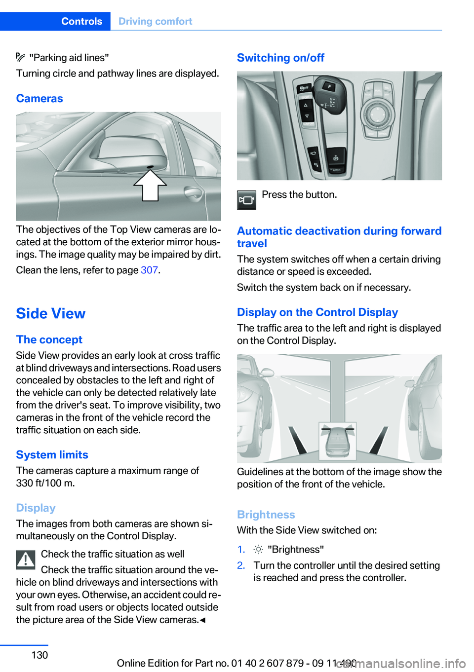
Press the button.
Automatic deactivation during forward
travel
The system switches off when a certain driving
distance or speed is exceeded.
Switch the system back on if necessary.
Display on the Control Display
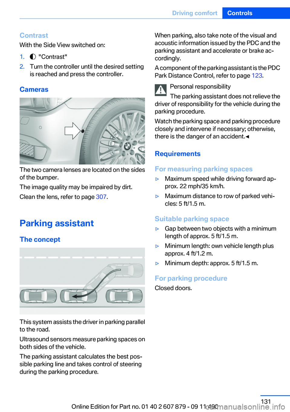
The traffic area to the left and right is displayed
on the Control Display.
Guidelines at the bottom of the image show the
position of the front of the vehicle.
Brightness
With the Side View switched on:
1. "Brightness"2.Turn the controller until the desired setting
is reached and press the controller.Seite 130ControlsDriving comfort130
Online Edition for Part no. 01 40 2 607 879 - 09 11 490
Page 131 of 335
Contrast
With the Side View switched on:1. "Contrast"2.Turn the controller until the desired setting
is reached and press the controller.
Cameras
The two camera lenses are located on the sides
of the bumper.
The image quality may be impaired by dirt.
Clean the lens, refer to page 307.
Parking assistant
The concept
This system assists the driver in parking parallel
to the road.
Ultrasound sensors measure parking spaces on
both sides of the vehicle.
The parking assistant calculates the best pos‐
sible parking line and takes control of steering
during the parking procedure.
When parking, also take note of the visual and
acoustic information issued by the PDC and the
parking assistant and accelerate or brake ac‐
cordingly.
A component of the parking assistant is the PDC
Park Distance Control, refer to page 123.
Personal responsibility
The parking assistant does not relieve the
driver of responsibility for the vehicle during the
parking procedure.
Watch the parking space and parking procedure
closely and intervene if necessary; otherwise,
there is the danger of an accident.◀
Requirements
For measuring parking spaces▷Maximum speed while driving forward ap‐
prox. 22 mph/35 km/h.▷Maximum distance to row of parked vehi‐
cles: 5 ft/1.5 m.
Suitable parking space
▷Gap between two objects with a minimum
length of approx. 5 ft/1.5 m.▷Minimum length: own vehicle length plus
approx. 4 ft/1.2 m.▷Minimum depth: approx. 5 ft/1.5 m.
For parking procedure
Closed doors.
Seite 131Driving comfortControls131
Online Edition for Part no. 01 40 2 607 879 - 09 11 490
Page 132 of 335
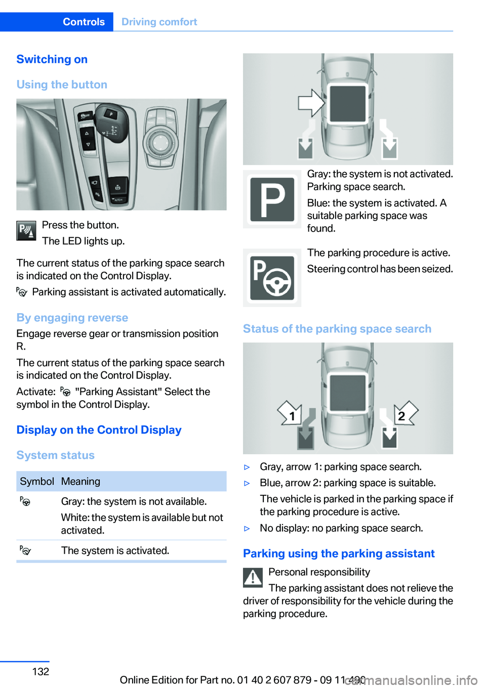
Switching on
Using the button
Press the button.
The LED lights up.
The current status of the parking space search
is indicated on the Control Display.
Parking assistant is activated automatically.
By engaging reverse
Engage reverse gear or transmission position
R.
The current status of the parking space search
is indicated on the Control Display.
Activate:
"Parking Assistant" Select the
symbol in the Control Display.
Display on the Control Display
System status
SymbolMeaning Gray: the system is not available.
White: the system is available but not
activated. The system is activated.
Gray: the system is not activated.
Parking space search.
Blue: the system is activated. A
suitable parking space was
found.
The parking procedure is active.
Steering control has been seized.
Status of the parking space search
▷Gray, arrow 1: parking space search.▷Blue, arrow 2: parking space is suitable.
The vehicle is parked in the parking space if
the parking procedure is active.▷No display: no parking space search.
Parking using the parking assistant
Personal responsibility
The parking assistant does not relieve the
driver of responsibility for the vehicle during the
parking procedure.
Seite 132ControlsDriving comfort132
Online Edition for Part no. 01 40 2 607 879 - 09 11 490