Ecu BMW 530i 2000 E39 User Guide
[x] Cancel search | Manufacturer: BMW, Model Year: 2000, Model line: 530i, Model: BMW 530i 2000 E39Pages: 1002
Page 132 of 1002
Downloaded from www.Manualslib.com manuals search engine
11 3-38
I Cylinder Head Removal and Installation
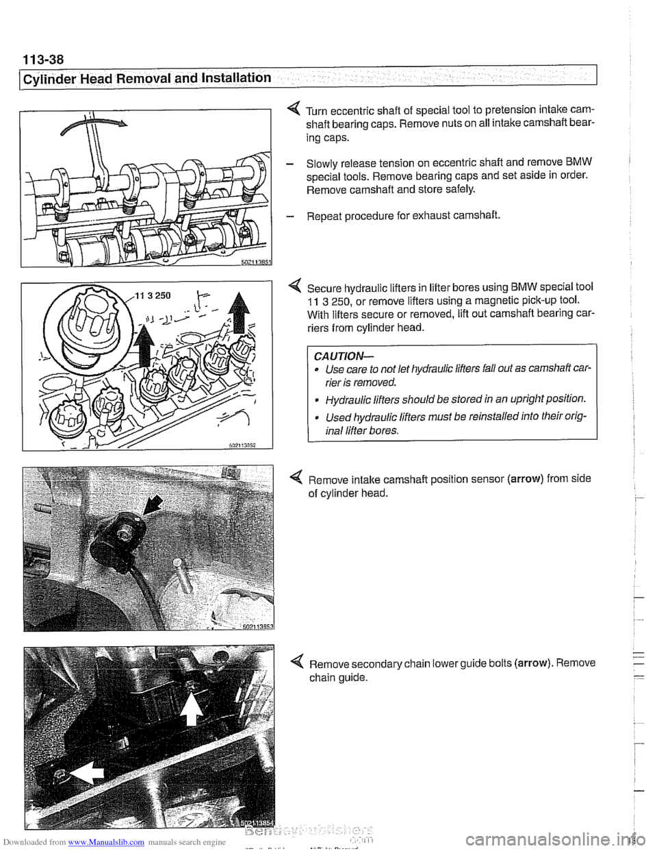
< Turn eccentric shaft of special tool to pretension intake cam-
shaft bearing caps. Remove nuts on all intake camshaft bear-
ing caps.
- Slowly release tension on eccentric shaft and remove BMW
spec~al tools. Remove bearing caps and set as~de in order.
Remove camshaft and store safely.
- Repeat procedure for exhaust camshaft.
4 Secure hydraulic lifters in lifter bores using BMW speclal tool
11 3 250, or remove lifters using a magnetic pick-up tool.
With lifters secure or removed, lift out camshaft bearing car-
riers from cylinder head.
Use care to not let hydraulic lifters fall out as camshaft car-
rier is removed.
Hydraulic lifters should be stored
ln an uprightpositlon.
Used hydraulic lifters must be reinstalled into their orig-
inal lifter bores.
4 Remove intake camshaft position sensor (arrow) from side
of cylinder head.
4 Remove secondary chain lowerguide bolts (arrow). Remove
chain guide.
Page 135 of 1002
![BMW 530i 2000 E39 User Guide Downloaded from www.Manualslib.com manuals search engine
. - ..
Cylinder Head Removal and installation] --
- Secure cylinder head bolts by torquing an additional 90"
each for Stage 2 and 3.
T BMW 530i 2000 E39 User Guide Downloaded from www.Manualslib.com manuals search engine
. - ..
Cylinder Head Removal and installation] --
- Secure cylinder head bolts by torquing an additional 90"
each for Stage 2 and 3.
T](/img/1/2822/w960_2822-134.png)
Downloaded from www.Manualslib.com manuals search engine
. - ..
Cylinder Head Removal and installation] --
- Secure cylinder head bolts by torquing an additional 90"
each for Stage 2 and 3.
Tightening torques
Cylinder head to engine block
(aluminum block)
Stage
1 40 Nm (30 it-lb)
Stage 2 +90°
Stage 3 80'
4 lnstall intake camshaft position sensor (arrow).
4 Install lower secondary chain guide. Tighten tom bolts to
specifications. The bolt on the intake camshaft side is long
and extends into the engine block.
4 Install and tighten cylinder head-to-lower timing chain cover
bolts (arrows). (Photo shows camshafts in place).
Tightening torque Secondary chain guide to cylinder head
10 Nm (89 in-lb)
Cylinder head to lower timing chain cover
M6 10 Nm (89 in-lb)
M7 15 Nm (1 1 it-lb)
Page 138 of 1002
Downloaded from www.Manualslib.com manuals search engine
11 3-44
I Cylinder Head Removal and Installation
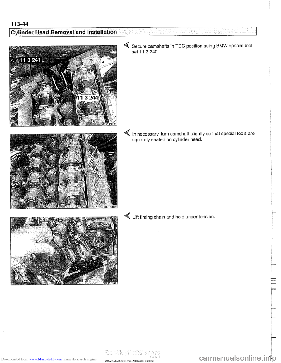
4 Secure camshafts in TDC position using BMW special tool
set
11 3 240.
4 In necessary, turn camshaft slightly so that special tools are
squarely seated on cylinder head.
4 Lift timing chain and hold under tension.
Page 146 of 1002
Downloaded from www.Manualslib.com manuals search engine
. .- --
Cylinder Head Removal and Installation
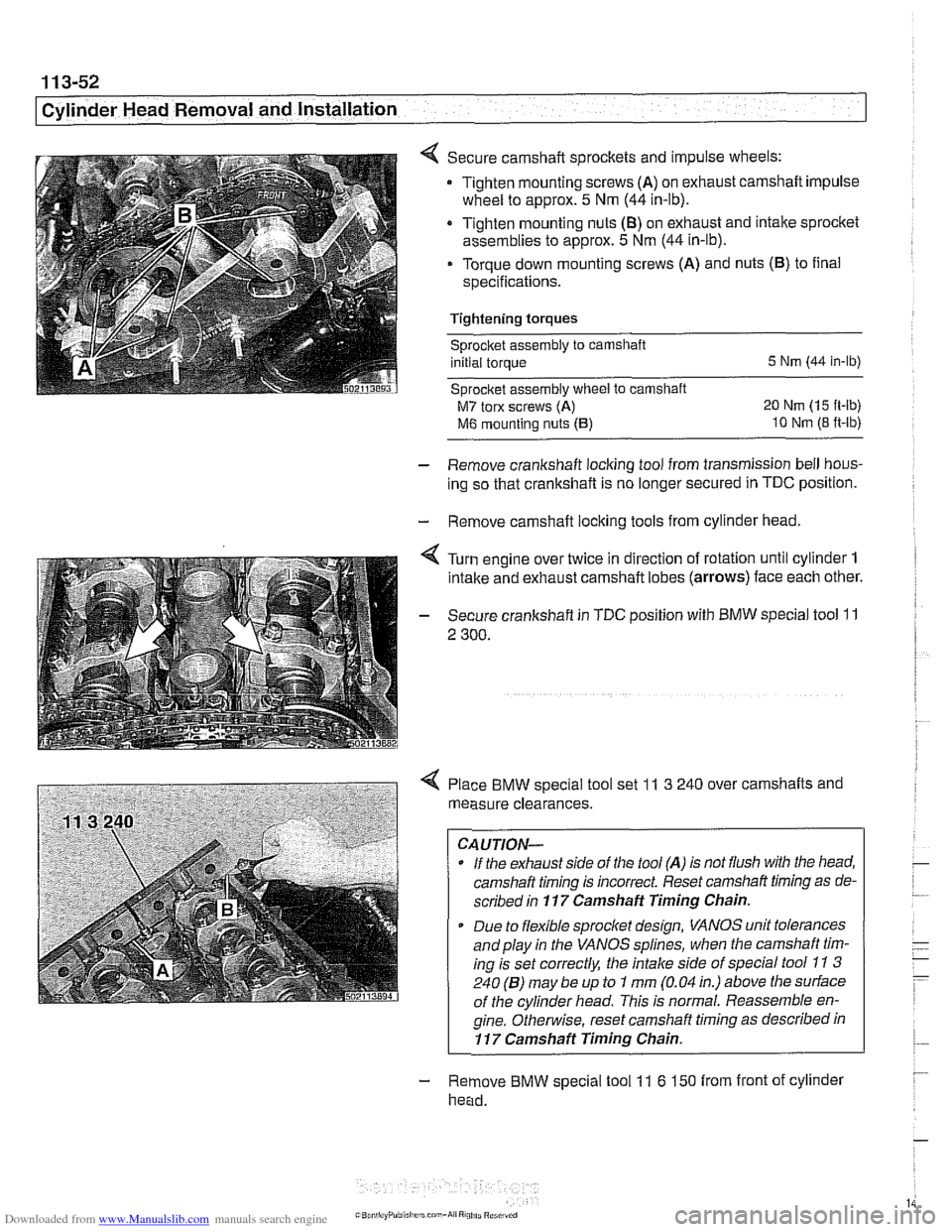
Secure camshaft sprockets and impulse wheels:
Tighten mounting screws
(A) on exhaust camshaft impulse
wheel to approx.
5 Nm (44 in-lb).
Tighten mounting nuts
(8) on exhaust and intake sprocket
assemblies to approx.
5 Nm (44 in-lb).
Torque down mounting screws (A) and nuts (B) to final
specifications.
Tightening torques
sprocket assembly to camshaft
initial torque
5 Nm (44 in-lb)
Sprocket assembly
wheel to camshaft
M7 torx screws (A) 20 Nm (15 ft-lb)
M6 mounting nuts (5) 10 Nm (8 ft-lb)
- Remove crankshaft locking tool from transmission bell hous-
ing so that crankshaft is no longer secured in
TDC position.
- Remove camshaft locking tools from cylinder head.
4 Turn engine over twice in direction of rotation until cylinder 1
intake and exhaust camshaft lobes (arrows) face each other.
- Secure crankshaft in TDC position with BMW special tool 11
2 300.
4 Place BMW special tool set 11 3 240 over camshafts and
measure clearances.
CAUTION-
- If the exhaust side of the tool (A) is not flush with tlie head,
camshaft timing is incorrect Reset camshaft timing as de-
scribed in
117 Camshaft Timing Chain.
* Due to flexible sprocket design, VANOS unit tolerances
and play in the VANOS splines, when the camshaft tim-
ing is set correctly, the intake side of special tool
11 3
240 (6) may be up to 1 mm (0.04 in.) above the surface
of the cylinder head. This is normal. Reassemble en-
gine.
Othe~lise, reset camshaft timing as described in
11 7 Camshaft Timing Chain.
- Remove BMW special tool 11 6 150 from front of cylinder
head.
Page 148 of 1002
Downloaded from www.Manualslib.com manuals search engine
. ." ".
[Cylinder Head Removal and Installation - .. - -1 -
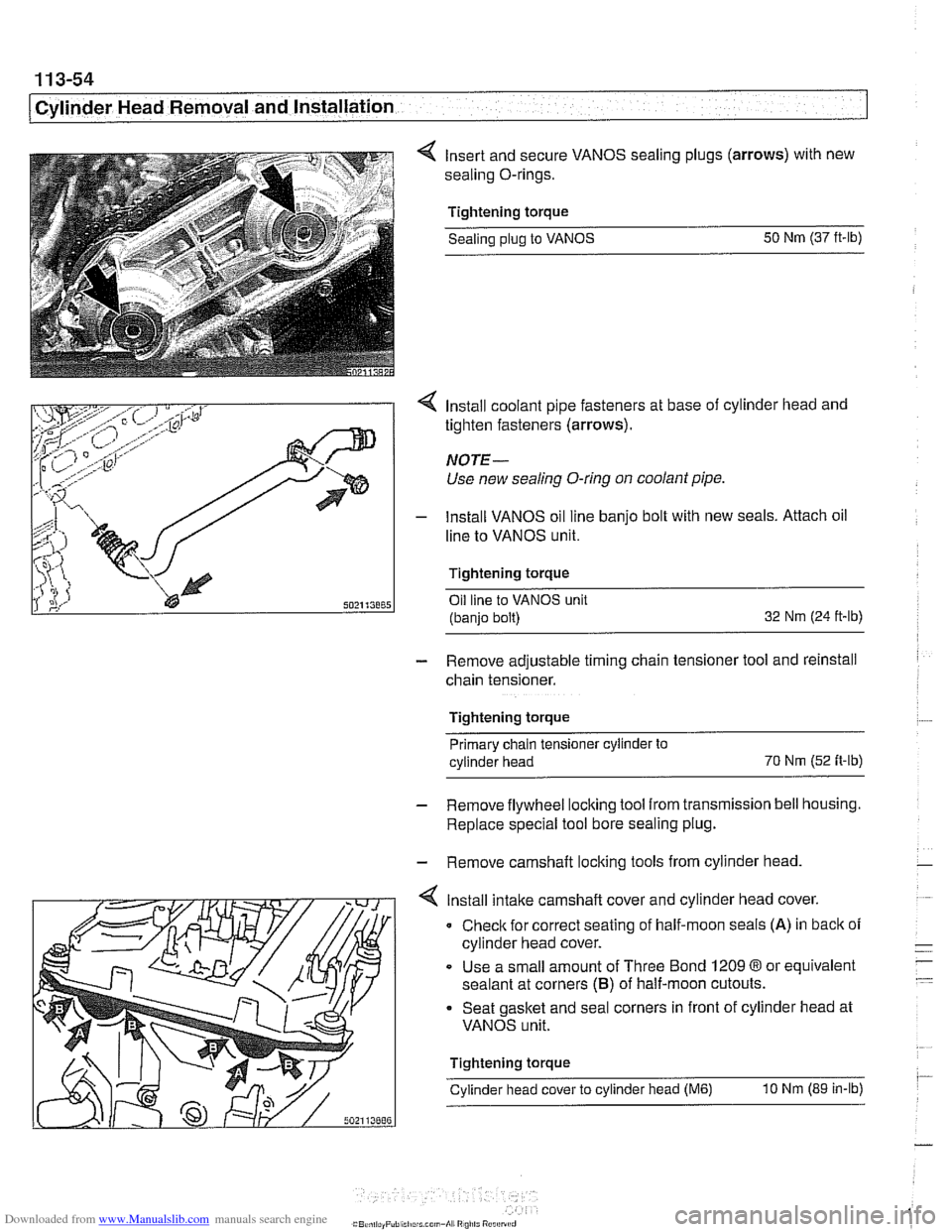
4 Insert and secure VANOS sealing plugs (arrows) with new
sealing O-rings.
Tightening torque Sealing
plug to VANOS 50
Nm (37 ft-lb)
4 Install coolant pipe fasteners at base of cylinder head and
tighten fasteners (arrows).
NOTE-
Use new sealing O-ring on coolant pipe.
- lnstall VANOS oil line banjo bolt with new seals. Attach oil
line to VANOS unit.
Tightening torque Oil line to VANOS unit
(banjo bolt) 32
Nm (24 ft-ib)
- Remove adjustable timing chain tensioner tool and reinstall
chain tensioner.
Tightening torque Primary chain tensioner cylinder to
cylinder head 70
Nm
(52 fi-ib)
- Remove flywheel locking tool from transmission bell housing.
Replace special tool bore sealing plug.
- Remove camshaft locking tools from cylinder head
4 lnstall intake camshaft cover and cylinder head cover.
0 Check for correct seating of half-moon seals (A) in back of
cylinder head cover.
Use a small amount of Three Bond
1209 8 or equivalent
sealant at corners
(B) of half-moon cutouts.
Seat gasket and seal corners in front of cylinder head at
VANOS unit.
Tightening torque
Cylinder head cover to cylinder head
(M6) 10 Nm (89 in-lb)
Page 159 of 1002
Downloaded from www.Manualslib.com manuals search engine
1 13-65
Cylinder Head Removal and Installation /
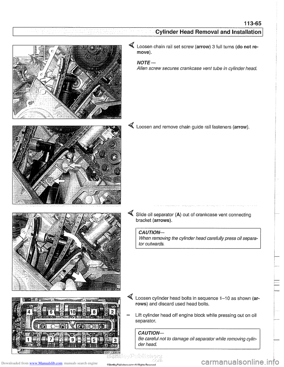
Loosen chain rail set screw (arrow) 3 full
move).
NOTE-
Allen screw secures crankcase vent tube
4 Loosen and turns
(do not re-
in cylinder head.
remove chain guide rail fasteners (arrow).
Slide oil separator
(A) out of cranltcase vent connecting
bracket (arrows).
CAUTIOI\C
When removing the cylinder head carefully press oil separa-
tor outwards.
Loosen cylinder head bolts in sequence
1-10 as shown (ar-
rows) and discard used head bolts.
Lift cylinder head off engine block while pressing out on oil
separator.
CAUTIOI\C
Be careful not to damage oil separator while removing cylin-
der head.
Page 161 of 1002
Downloaded from www.Manualslib.com manuals search engine
1 13-67
Cylinder Head Removal and lnstaKI --
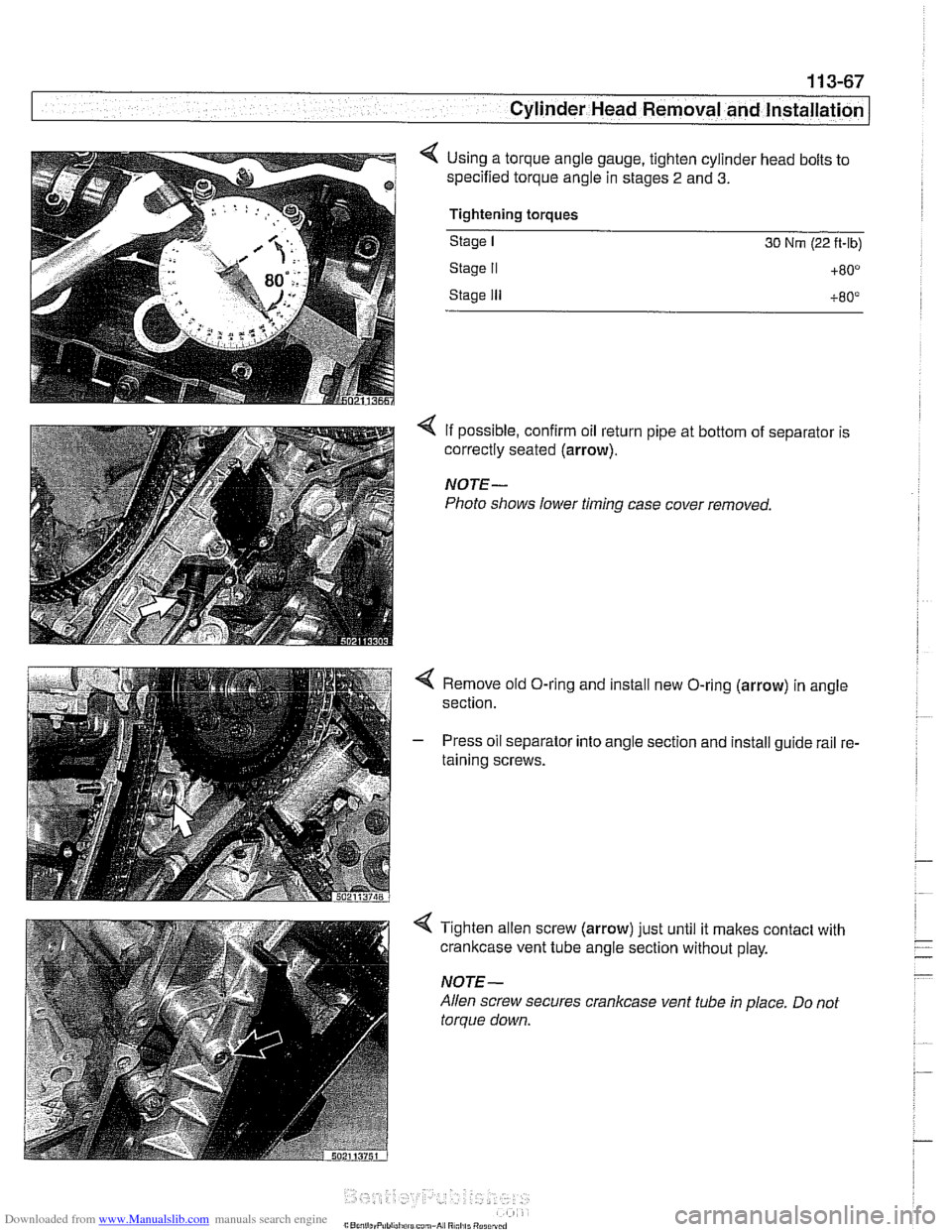
< Using a torque angle gauge, tighten cylinder head bolts to
specified torque angle in stages
2 and 3.
Tightening torques
Stage I 30 Nrn (22 ft-lb)
Stage II +80°
Stage Ill +80°
4 If possible, confirm oil return pipe at bottom of separator is
correctly seated
(arrow).
NOTE-
Photo shows lower timing case cover removed.
< Remove old O-ring and install new O-ring (arrow) in angle
section.
- Press oil separator into angle section and install guide rail re-
taining screws.
4 Tighten allen screw (arrow) just until it makes contact with
crankcase vent tube angle section without play.
NOTE-
Allen screw secures crankcase vent tube in place. Do not
torque down.
Page 193 of 1002

Downloaded from www.Manualslib.com manuals search engine
Cylinder Head and Valvetrain
4 Secure hydraulic lifters in lifter bores using BMW special tool
11 3 250, or remove lifters using a magnetic pick-up tool.
4 Remove camshaft bearing carrier from cylinder head.
CA UTION-
Camshaftbearing carriers must be reinstalledin their original
/ locations (E for ir;fal
Do not let hydraulic lifters fall out as the camshaft carrier is
removed.
Hydraulic lifters should be stored in an upright position.
Used hydraulic lifters
must be replaced into original lifter
bores.
Camshafts and lifters, installing
(M52 Engine)
Lubricate camshafts, camshaft carriers, bearing caps, hy-
draulic liflers, friction washers, splined shafts and spline hubs
with assembly lubricant before installation.
Make sure
the cranltshaft, which had been rotated approxi-
mately
30" opposite the direction of engine rotation from
TDC, is still in thatposition before lowering the
camshaffs into
position. All pistons must be out of TDC position to prevent
valve/piston interference when the camshalts are installed.
Before installing camshaft carriers, examine bearing bores
(arrows) on hydraulic lifter bores for signs of wear.
Page 201 of 1002
Downloaded from www.Manualslib.com manuals search engine
Cylinder Head and Valvetrain
NOTE-
The camshaft bearing caps are coded with a letter and a
number. For example, "A
1" is the first exhaust camshaft
bearing cap
at the front of the engine, and "El "is the intake
camshaft bearing cap at the front of the engine.
-. -
The camshafts are stamped with a code letter - "E for the
intake side and
'X" for the exhaust side.
"E is for Einlap. (German for intake) and 'XA7s for Auspuff.
(German for exhaust).
- Repeat procedure for exhaust camshaft
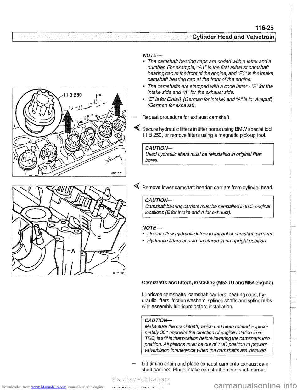
< Secure hydraulic lifters in lifter bores using BMW special tool
11 3 250, or remove lifters using a magnetic pick-up tool.
I CAUTION-
Used liydraulic lifters must be reinstalled in original lifter
1 bores.
4 Remove lower camshaft bearing carriers from cylinder head.
CAUTION- Camshaft bearing carriers must be reinstalled in their original
locations
(E for intalce and A for exhaust).
NOTE- Do not allow hydraulic lifters to fall out of camshaft carriers.
Hydraulic lifters should be stored in an upright position.
Camshafts and lifters, installing (M52TU and M54 engine)
Lubricate camshafts, camshaft carriers, bearing caps, hy-
draulic lifters, friction washers, splined shafts and
spline hubs
with assembly
lubricant before installation.
CAUTION-
Make sure the crankshaft, which had been rotated approxi-
mately
30" opposite the direction of engine rotation from
TDC, is
stillin thatposition before lowering the camshafts into
position. Allpistons must be out of
TDCposition to prevent
valve/piston inteiference when the carnshafis are installed.
- Lift timing chain and place exhaust cam onto exhaust cam-
shaft carriers. Place
intake camshaft on camshaft carrier.
Page 205 of 1002
Downloaded from www.Manualslib.com manuals search engine
--
Cylinder Head and valvetrain1
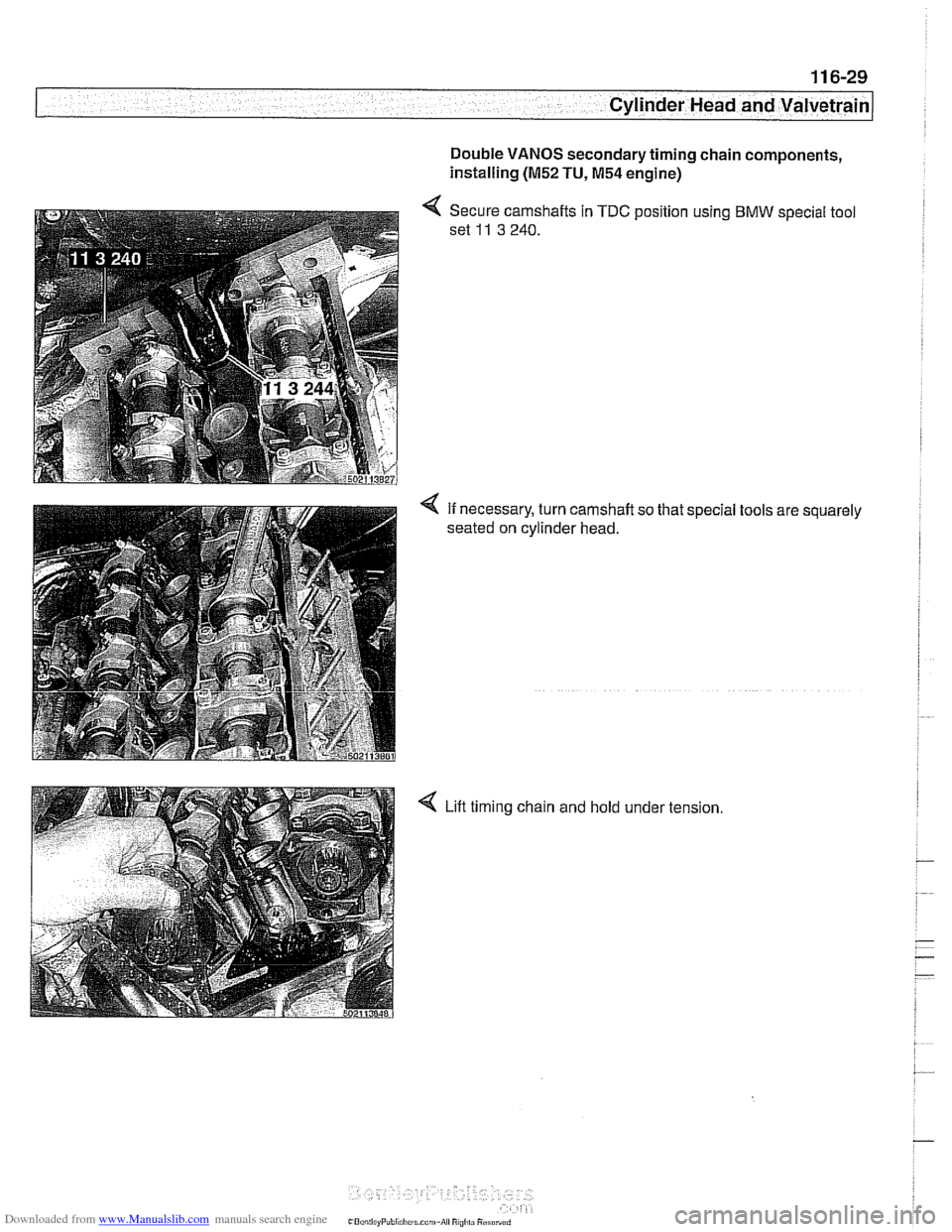
Double VANOS secondary timing chain components,
installing
(M52 TU, M54 engine)
< Secure camshafts in TDC position using BMW special tool
set
11 3 240.
4 If necessary, turn camshaft so that special tools are squarely
seated on cylinder head.
4 Lift timing chain and hold under tension