fault code BMW 530i 2001 E39 Repair Manual
[x] Cancel search | Manufacturer: BMW, Model Year: 2001, Model line: 530i, Model: BMW 530i 2001 E39Pages: 1002
Page 967 of 1002

Downloaded from www.Manualslib.com manuals search engine
On-Board Diagnostics
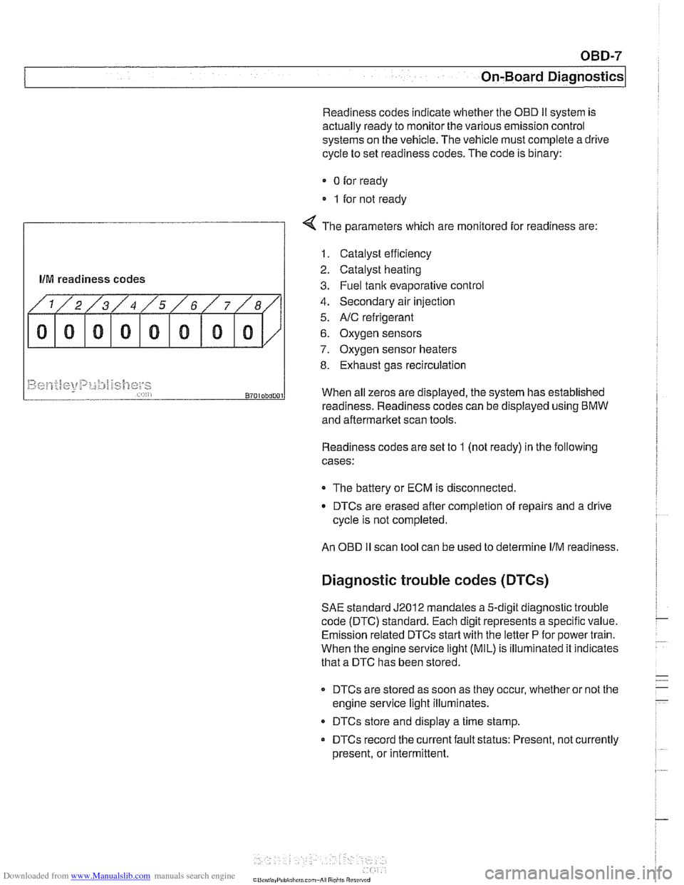
Readiness codes indicate whether the OED Ii system is
actually ready to monitor the various emission control
systems on the vehicle. The vehicle must complete a drive
cycle to set readiness codes. The code is binary:
0 for ready
1 for not ready
f
4 The parameters which are monitored for readiness are:
llM readiness codes
1. Catalyst efficiency
2. Catalyst heating
3. Fuel tank evaporative control
4. Secondary air injection
5.
NC refrigerant
6. Oxygen sensors
7. Oxygen sensor heaters
8. Exhaust gas recirculation
Readiness codes are set to 1 (not ready) in the following
cases:
~9~~.f~[<+t~t~p:,~;:#j~~{]~y~ ,,... , , 8701Dbd001
The battery or ECM is disconnected.
When
all zeros are displayed, the system has established
DTCs are erased after completion of repairs and a drive
cycle is not completed.
readiness. Readiness codes
can be displayed using BMW
and aftermarket scan tools.
An
OED II scan tool can be used to determine IIM readiness.
Diagnostic trouble codes (DTCs)
SAE standard J2012 mandates a 5-digit diagnostic trouble
code (DTC) standard. Each digit represents a specific value.
Emission related DTCs
start with the letter P for power train.
When the engine service
light (MIL) is illuminated it indicates
that a DTC has been stored.
DTCs are stored as soon as they occur, whether or not the
engine service light illuminates.
DTCs store and display a time stamp.
DTCs record the current fault status: Present, not currently
present, or intermittent.
Page 969 of 1002

Downloaded from www.Manualslib.com manuals search engine
On-Board Diagnostics
DIAGNOSTIC TROUBLE CODES
(DTCs)
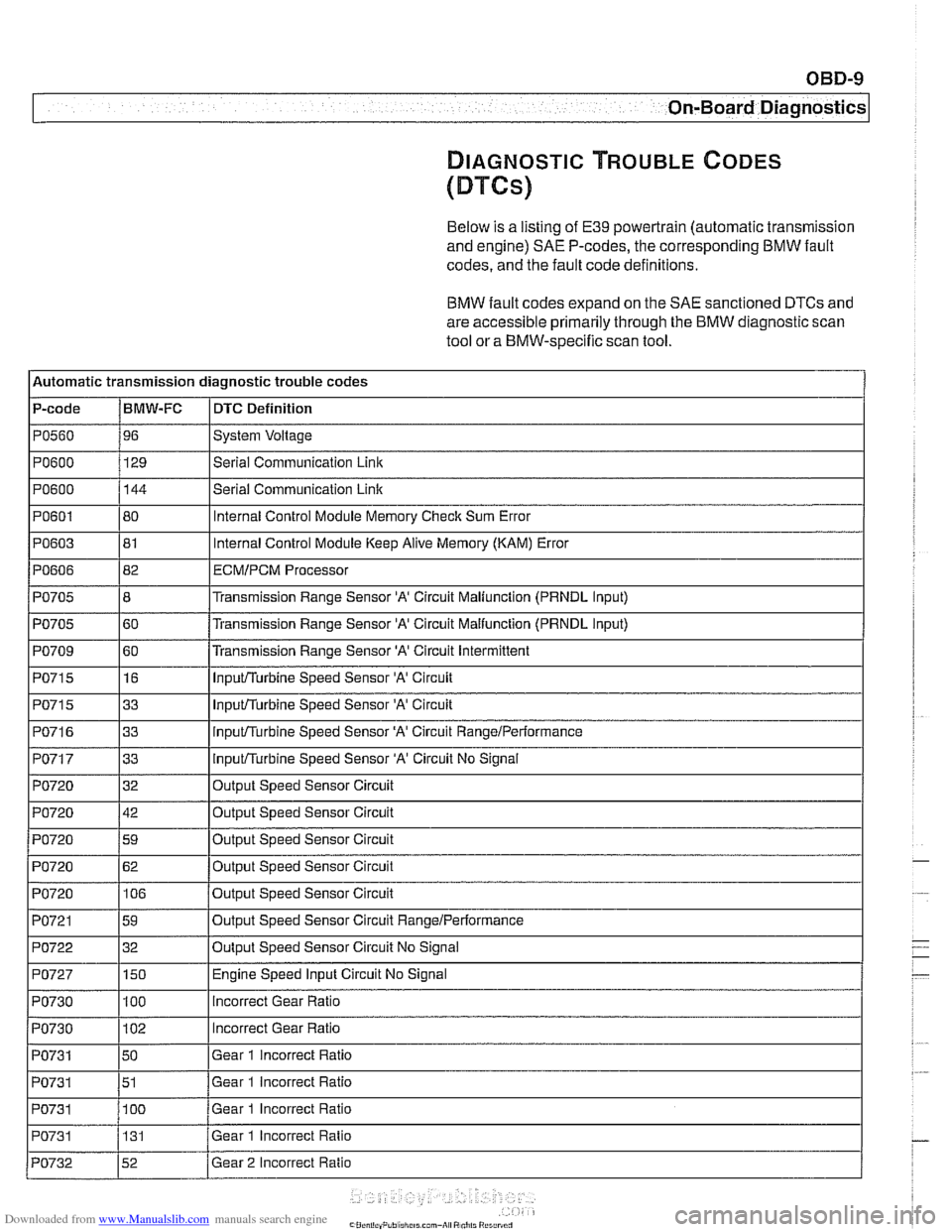
Below is a listing of E39 powertrain (automatic transmission
and engine)
SAE P-codes, the corresponding BMW fault
codes, and the fault code definitions.
BMW fault codes expand on the SAE sanctioned DTCs and
are accessible primarily through the BMW diagnostic scan
tool or a BMW-specific scan tool.
l~utomatic transmission diagnostic trouble codes
P-code
IBMW-FC I DTC Definition
Ip0560 196 ISystem Voltage I
IPO~OO I129 l~eriai Communication Link I
1~0715 116 I InpuVTurbine Speed Sensor 'A' Circuit I
PO600
PO601
PO603
PO606
PO705
PO705
PO709
144
80
81
82
8
60
60
PO71 5
PO71 6
PO717
PO720
PO720
PO720
I I
PO721 159 loutput Speed Sensor Circuit RangeIPerformance I
Serial Communication Link
Internal Control Module Memory Check Sum Error
Internal Control Module Keep Alive Memory (KAM) Error
ECMIPCM Processor
Transmission Range Sensor 'A' Circuit Maliunction (PRNDL Input)
Transmission Range Sensor
'A' Circuit Malfunction (PRNDL input)
Transmission Range Sensor
'A' Circuit Intermittent
I I'
1~0722 132 IOutput Speed Sensor Circuit No Signal I
33
33
33
32
42
59
PO720
I I
PO727 1150 I Engine Speed Input Circuit No Signal
InpuVTurbine Speed Sensor 'A' Circuit
inpuVTurbine Speed Sensor 'A' Circuit RangeiPerformance
InpuVTurbine Speed Sensor 'A' Circuit No Signal
Output Speed Sensor Circuit
Output Speed Sensor Circuit
Out~ut Speed Sensor Circuit
PO720 1106 /output Speed Sensor Circuit
62
Output Speed Sensor Circuit
PO730
PO730
PO731
PO731
PO731 I I
100
102
50
51
100
PO731
incorrect Gear Ratio
Incorrect Gear Ratio
Gear 1 incorrect Ratio
Gear 1 incorrect Ratio
Gear 1 Incorrect Ratio
PO732 152 /Gear 2 Incorrect Ratio
131
Gear
1 Incorrect Ratio
Page 992 of 1002

Downloaded from www.Manualslib.com manuals search engine
2 INDEX
Battery, starter, alternator
alternator (generator)
121-10
6-cylinder engine, removingi
installing 121-15
M62 engine 121-16
M62 TU engine (water cooled)
121-18
battery
121-5 charging 121-9
safety terminal 121-3
testing 121-5 charging system, troubleshooting
121-12
starter
121-1 9
6-cylinder engine, removingi instaliinq 121-20 . V-8 engine, rernovinglinsialiing
121-21
solenoid, removinglinstalling
121-23 troubleshooting 121-19
see also Maintenance
Bearing, wheel
see Front suspension
see also Rear suspension
Belts see Maintenance, drive belts
Blade, wiper
see Wipers and Washers
Blower motor see
A/C
BMW emblem
see Exterior trim
BMW special tools 010-18 see also special tools section at
beginning
of each repair group
Body dimensions 400-2
interior features
400-9 salety and security 400-7
Body side molding
see Exterior trim
Bonnet see Engine hood
Boot see Trunk
Brake fluid
020-24, 340-8
Brake fluid pressure sensor
340-30
Brakes
ABS, ASC or DSC system
300-12
component replacement 340-26
ASCIDSC switch
see Switches
bleeding
bralces 340-8
brake booster 340-1 9 bralce Dads. caiioers and rotors ,., 340-1 1
descriotion 300-10
e~ectrdnic brake & stability 300-11
light switch
see Switches
master cylinder
340-16 pariking brake 340-22
troubleshooting 340-5
Bulbs see Lights
Bumper
lront 510-6 height, adjusting 510-12
rear 510-9
Bus system
600-4
Camber
320-33
Camshaft
removingiinslaiiing
M52 engine 116-12
M52 TU
/ M54 engine 116-1 9 M62 engine 11 6-39
wear
116-6
Camshaft position sensors
see ignition system
Camshaft timing chain
adjusting M52 engine
117-22
M52 TU I M54 engine 117-43
M62 engine 117-79 removinglinstalling
M52 engine 117-26
M52TU 1 M54 engine 113-46.116-
28
M62 engine 117-66
Capacities, fluid
020.10
Car rnemorvlicev memorv . . 600-10
see also Centrai
lociking
Carbon canister, activated
see Fuel
tank
Caster
320-33
Catalytic converter and oxygen sensor 020-19
see also Exhaust system: exhaust
manilolds
Cautions
001-3
CD changer
650-4
Center bearing, driveshaft
see Driveshait
Center brake light
sedan
630-13
Center console
513-3
Centrai body electronics (ZKE 111)
600-6
Central locking
car memoryiey memory 515.12 general module iunctions 515-2
remote entry (FZV) 515-8
remote lkey initialization 515-10 single lociddouble ioclk 515-6
switch 515-4
Chain
see Camshaft liming chain
Characteristic map (electrically heated) thermostat
see Electrically heated thermostat
Charging system
see Battery, starter, alternator
Cluster see instruments
Clutch fluid see Maintenance
hydraulics
210-4
mechanical 210-9
switch
see Switches, pedal ciuster
variations
210.10
Codes, fault OED-1
Coil
see Ignition system
Coil spring
see Front suspension
see also Rear
suspe nsion
Page 995 of 1002

Downloaded from www.Manualslib.com manuals search engine
INDEX 5
WARNING
Your common sense, good
judgement, and general alerlness are
crucial lo
safe and successful service ivork. Before attempling any work on
your
BMW be sure lo read 001
General Warnings and Cautions
and the copyright page at the
fronl of
Ihe manual. Review these warnings
and
cautions each lime you prepare
to work on your BMW Please also
read any warnings and cautions tliat
accompany Nie procedures in the
manual.
Exhaust manifold see Exhaust system
Exhaust system diagrams
180.1 1
exhaust manifolds, removinglinstalling
180-4 muifier, replacing 180-8
oxygen sensors 180-8
and catalytic converter 020-1 9
see also Fuel injection
removinglinstalling 180-2
see also Maintenance
Expansion tank
see Cooling system
Expansion valve
see
NC
Exterior lighting
see
Lights
Exterior trim
BMW emblem
(Roundel), removing1
installing
510-13 body side molding, replacing 510.13
grill, removinglinsialiing 510-14
headlight housing trim, removing1
installing 510-14
outside mirror
510-2
EWS (electronic immobilization)
515-21 ring antenna,
iemovinglinstaiting
320-1 1
Fan see Cooling system Fault
codes
OBD-2
storage
100-4. 600.10
Fender
front, rernovinglinstailing
410-2
Filters see Maintenance
Final drive
lubricant
speciiicatiorls 020-9
mounh, replacing 331-12
oil level 020-26. 331-6
removinglinslalling 331-5 seals 331-7
Firing order
see Ignition system
FtS
see Interior protectiorl
Flex disc
see Driveshaft
Fluids and lubricants see Maintenance
Flywheel removinglinstalling 210-13
Fogllght
see Lights
Front centering guide see Driveshatt
Front oil seal
see
Crankshaft oil seals
Front suspension control arm
310-12 description 300-2
ride height 300-14
stabilizer bar, removinglinstalling
310-21
strutslsprings 31
0-4
tension strut 310-16
thrust arm 310-12 variations 310-4
wheel bearing 310-18
see also Maintenance
Fuel filter
see Maintenance
Fuet injection applications 130-2
Bosch M5.2, M5.2.1 130-46
Bosch ME 7.2 130-66 fuel delivery
see 130 under appropriate iuel
injection system
see also Fuel pump
see also
Fuet tank
oxygen sensors
130-72, 180-8
Siemens MS 41.1 130-7 Siemens MS 42.0. MS 43.0 130-23
Fuel injector
see 130 under appropriate fuel
injection system
Fuel level sender
160-15
see also Fuei pump
Fuel pressure
160-10
see also Fuel pump
Fuel pump
160-3
electrical circuit, testino 160-7
1
removinglinstalling (includes right side
iuel levei sender) 160-15
siphon pump, removinglinstaliing
160-19
troubleshooting 160-6 see also Fuel tank
Fuel rail
see 130 under appropriate iuel
injection system
Fuei supply
130-6
see also Fuei pump
see also
Fuet lank
Fuel
tank
312-way valve (running losses.
removinglinstalling
160-24 carbon canister 160-24
draining 160-20
evaporative control system 160-3
expansion tank, removinglinstalling
160-23
I
leak detection unit (LDP or DM-TL),
rernovinoiinstallino 160-24
level senier 160-15
removinglinstalling 160-21
Fuse locations
610-29
RV (remote entry)
see Central
locl(ing
Fan clutch
see Cooling system, cooling fan