CARRIER BMW 540i 1997 E39 User Guide
[x] Cancel search | Manufacturer: BMW, Model Year: 1997, Model line: 540i, Model: BMW 540i 1997 E39Pages: 1002
Page 327 of 1002
Downloaded from www.Manualslib.com manuals search engine
Lubrication stern/
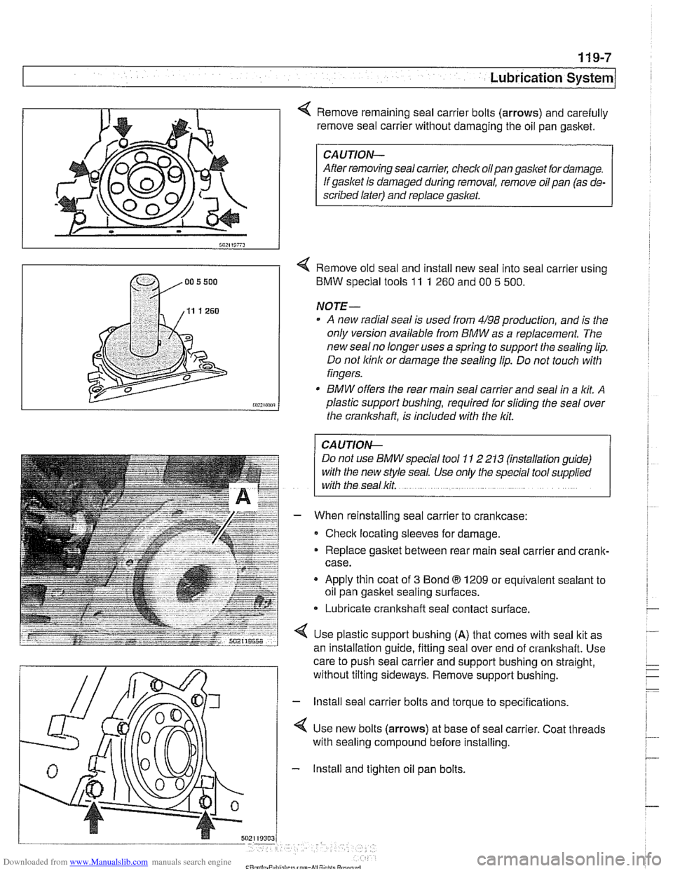
Remove remaining seal carrier bolts (arrows) and carefully
remove seal carrier without damaging the oil pan
gasltet.
CAUTION-
After removing seal carrier, checlc oilpan gasket for damage.
If gasket is damaged during removal, remove oil pan (as de-
scribed later) and replace
gasket.
< Remove old seal and install new seal into seal carrier using
BMW special tools
11 1 260 and 00 5 500.
NOTE-
A new radial seal is used from 4/98 production, and is the
only version available from
BMW as a replacement. The
new
sealno longer uses a spring to support the sealing lip.
Do not
lcinlc or damage the sealing lip. Do not touch with
fingers.
* BMW offers the rear main seal carrier and seal in a lit A
plastic support bushing, required for sliding the seal over
the crankshaft, is included with the
lcit.
I CAUTION- 1
Do not use BMW special tool 1 I 2 213 (mstallation guide)
with the new style seal. Use only the special tool
supphed
with the seal lcit.
When reinstalling seal carrier to crankcase:
Check locating sleeves for damage.
Replace
gasltet between rear main seal carrier and crank-
case.
Apply thin coat of
3 Bond 8 1209 or equivalent sealant to
oil pan gasket sealing surfaces.
* Lubricate crankshaft seal contact surface.
Use plastic support bushing
(A) that comes with seal ltit as
an installation
quide, fittina seal over end of crankshaft. Use - -
care to push seal carrier and support bushing on straight,
without tilting sideways. Remove support bushing.
- lnstall seal carrier bolts and torque to specifications.
4 Use new bolts (arrows) at base of seal carrier. Coat threads
with sealing compound before installing.
- Install and tighten oil pan bolts.
Page 328 of 1002
Downloaded from www.Manualslib.com manuals search engine
I Lubrication System -
- Remainder of assembly is reverse of disassembly.
Install flywheel, clutch or torque converter and
transmission.
Fill engine with oil.
- Run engine and check for leaks.
Tightening torques
Oil
drain plug fo oil pan (MI21 25 Nm (18 ft-lb)
Oil pan to engine
block
M6 (8.8 grade) 10 Nm (89 in-ib)
M6 (1 0.9 grade) 12 Nm (9 ft-lb)
M8 (8.8 grade) 22 Nm (1 6 it-lb)
Rear main seal carrier to crankcase
M6 10 Nm (89 in-lb)
ME 22 Nm (16 ft-lb)
Crankshaft rear main seal, replacing (V-8)
- Remove transmission. See 230 Manual Transmission or
240 Automatic Transmission.
- Manual transmission vehicles: Remove clutch pressure plate
and disc. See
210 Clutch.
- Remove flywheel. See 210 Clutch.
- Drain engine oil.
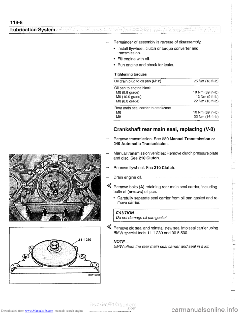
4 Remove bolts (A) retaining rear main seal carrier, including
bolts at (arrows) oil pan.
Carefully separate seal carrier from oil pan gasket and re-
move carrier.
CAUTION-
Do not damage oil pan gasket.
< Remove old seal and reinstall new seal into seal carrier using
) BMW special tools 11 1 230 and 00 5 500.
Page 329 of 1002
Downloaded from www.Manualslib.com manuals search engine
- When reinstalling seal carrier to crankcase:
Check locating sleeves for damage.
Replace gasitet between rear main seal carrier and
cranlt-
case.
Apply thin coat of
3 Bond 8 1209 or equivalent sealant to
oil pan
gasltet sealing surfaces.
* Lubricate crankshaft and seal contact surfaces.
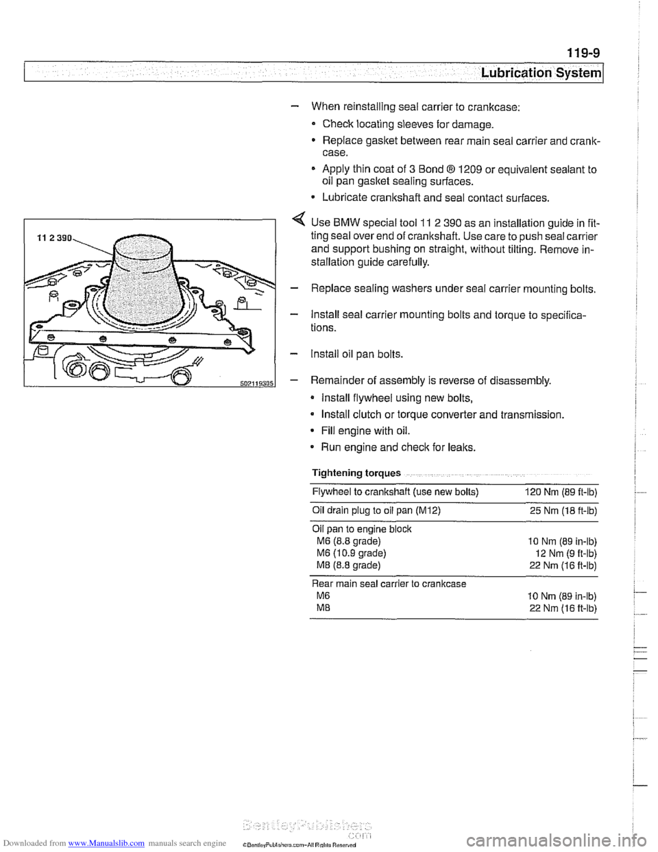
4 Use BMW special tool 11 2 390 as an installation guide in fit-
ting seal over end of cranltshaft. Use care to push seal carrier
and support bushing on straight, without tilting. Remove in-
stallation guide carefully.
- Replace sealing washers under seal carrier mounting bolts.
- Install seal carrier mounting bolts and torque to specilica-
tions.
- lnstall oil pan bolts.
- Remainder of assembly is reverse of disassembly.
Install flywheel using new bolts,
Install clutch or torque converter and transmission.
* Fill engine with oil.
Run engine and
checlt for leaks.
Tightening torques Flywheel to crankshaft (use new bolts)
120 Nm (89 ft-lb)
011 dra~n plug to 011 pan (M12) 25 Nm (18 ft-lb)
Oil pan to
eng~ne block
M6 (8.8 grade) 10 Nm (89 in-lb)
M6 (1 0 9 grade) 12 Nm (9 ft-lb)
M8 (8.8 grade) 22 Nm (16 ft-lb)
Rear main seal carrier to crankcase
M6 10 Nrn (89 in-lb)
ME 22 Nm (16 ft-lb)
Page 398 of 1002
Downloaded from www.Manualslib.com manuals search engine
130-8
Fuel Injection
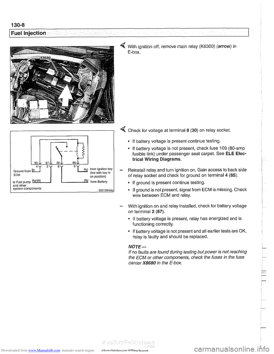
With ignition off, remove main relay (K6300) (arrow) in
E-box.
- With ignition on and relay installed, check for battery voltage
on terminal
2 (87).
4 Check for voltage at terminal 8 (30) on relay socket.
If battery voltage is present, relay has energized and is
functioning correctly.
Gmund from 6L (hot ~4th k~y key in Ern
2I '1
on position)
to
Fuel pump RdiWt Rd from Battery and other system components SOZI~O~~I~Y
If battery voltage is not present and all earlier tests are OK,
relay is faulty and should be replaced.
If
battery voltage is present continue testing.
If battery voltage is not present, check fuse 109 (80-amp
fusible link) under passenger seat carpet. See ELE Elec-
trical Wiring Diagrams.
- Reinstall relay and turn ignition on. Gain access to back side
of relay socket and check for ground on terminal
4 (85).
If ground is present continue testing.
If ground is not present, signal from ECM is missing. Check
NOTE-
If no faults are found during testing but power is not reaching
the
ECM or other components, check the fuses in the fuse
carrier
X8680 in the E-box.
wire
between ECM and relay.
Page 418 of 1002
Downloaded from www.Manualslib.com manuals search engine
130-28
Fuel Injection
ECM Relay
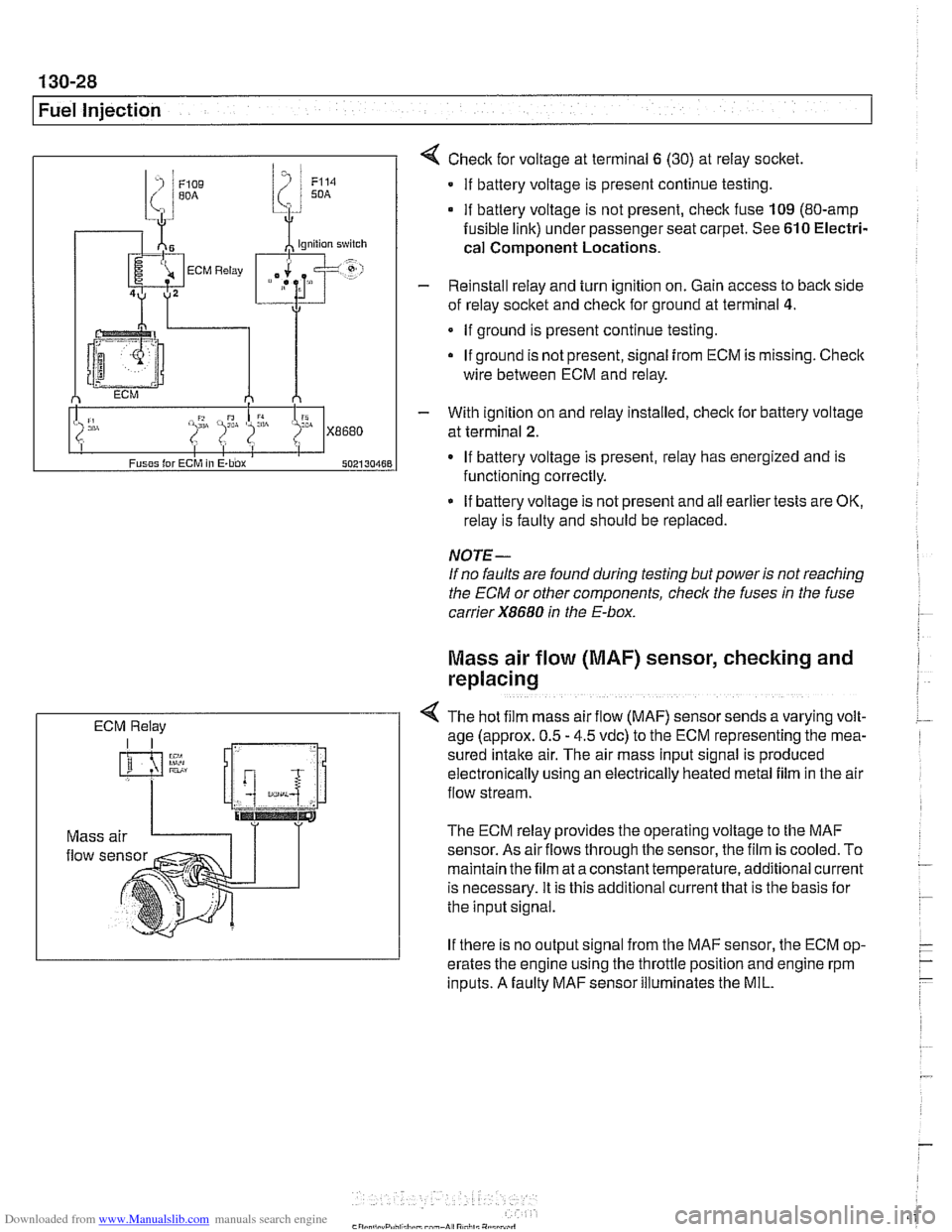
4 Check for voltage at terminal 6 (30) at reiay socket
If battery voltage is present continue testing.
if battery voltage is not present, check fuse 109 (80-amp
fusible link) under passenger seat carpet. See 610 Electri-
cal
Component Locations.
- Reinstall relay and turn ignition on. Gain access to back side
of reiay socket and check for ground at terminal
4.
If ground is present continue testing.
If ground is not present, signal
from ECM is missing. Check
wire between ECM and relay.
- With ignition on and reiay installed, check lor battery voltage
at terminal
2.
If battery voltage is present, relay has energized and is
functioning correctly.
If battery voltage is not present and
ail earlier tests are OK,
relay is faulty and should be replaced.
NOTE-
If no faults are found during testing but power is not reaching
the ECM or other components, check the fuses
in the fuse
carrier
X8680 in the E-box.
Mass air flow (MAF) sensor, checking and
replacing
4 The hot f~lm mass air flow (MAF) sensor sends a varying volt-
age (approx. 0.5 - 4.5 vdc) to the ECM representing the mea-
sured
Intake air. The alr mass input signal is produced
electron~caily uslng an electrically heated metal fllm in the air
flow stream.
The ECM relay provides the operating voltage to the MAF
sensor. As air
flows through the sensor, the film is cooled. To
maintain the film at a constant temperature, additional current
is necessary. It is this additional current that is the basis lor
the input signal.
If there is no output signal from the MAF sensor, the ECM op-
erates the engine using the throttle position and engine rpm
inputs. A faulty MAF sensor illuminates the MIL.
Page 432 of 1002
Downloaded from www.Manualslib.com manuals search engine
.-
/Fuel Injection
I ' I - I
9 /ln~ut l~oltaqe supply I Fuse carrier, engine electronics
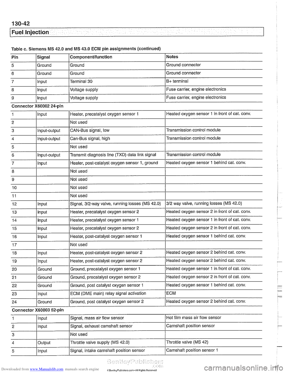
Table
c. Siemens MS 42.0 and MS 43.0 ECM pin assignments (continued) I ' I . I
Connector X60002 24-pin
1 linput IHeater, precatalyst oxygen sensor 1 I Heated oxygen sensor 1 in front of cat. conv.
I I I
18 llnout IHeater, post-catalyst oxygen sensor 2 ]Heated oxygen sensor 2 behind cat. conv.
Notes
Ground connector
Ground connector
B+ terminal
Fuse carrier, engine electronics
Pin
5
6
7
8
I I I
4 loutput l~hrottle valve supply (MS
42.0) I~hrottle valve (MS 42)
Signal
Ground
Ground Input
lnout
19
20 21
22
23
24
Connector
1
2
3
I I I
5 1 lnput ISignal, intake camshaft position sensor /camshaft position sensor 1
Componentlfunction
Ground
Ground
Terminal 30
Voltaae
SUDP~V
input
Ground
Ground
Ground
Input
Ground
X60003 52-pin
Input
Input
~ -
Heater, post-catalyst oxygen sensor 2
Ground, precatalyst oxygen sensor
1
Ground, precatalyst oxygen sensor 2
Ground, post catalyst oxygen sensor
1
ECM (DME main) relay signal activation
Ground, post catalyst oxygen sensor 2
Signal, mass air
flow sensor
Signal, exhaust camshaft sensor
Not used Heated
oxygen sensor 2 behind cat.
conv.
Heated oxygen sensor 1 in front of cat. conv.
Heated oxygen sensor 2 in front of cat. conv.
Heated oxygen sensor
1 behind cat. conv.
ECM
Heated oxygen sensor 2 behind cat. conv.
Hot film mass air flow sensor
Camshaft position sensor
Page 440 of 1002

Downloaded from www.Manualslib.com manuals search engine
130-50
Fuel Injection
Bosch M5.2
ECM relay
1 HoL al ail iirnel XOL a1 ail limes
i--[-----i F109 (BOA) electronics I L.$.....: .I:
ECM relay . . . . . . . . . ,
8,s
:,
6 1 .. ... ~~.~~. . ...... .-, Engine control ii~~-~.~~..~ ........ ~~~~~~.~~~~:. module relay -;I
Of?
,c,;,,,
< With ignition off, remove ECM relay (arrow) in electronics
box (E-box) at right rear of engine compartment.
NOTE-
Relay locations can vary. Conh relay identification by
matcliing wiring colors and terminal numbers.
4 Check for voltage at terminal 6 of main relay socket (30-red
wire). On M5.2 cars also check for battery voltage at terminal
8.
. . . . . . . . . ,
If battery voltage is present, continue testing
.
If battery voltage is not present, check large red wire(s) in
relay socltet. See
ELE Electrical Wiring Diagrams.
%P,,tt
- Reinstall relay and turn ignition on. Gain access to underside
of relay socket and
checlc for ground at terminal 4 (85-brown
wire).
. . . . . . . . . . . . - - - - - - - - - . - - - . . l ,,-. ; Engine i f .: , ; Fuse carrier .,A . :engine /;is? /control L.!.!! .... 1.: ...... !.::..! I lij :module electronics If
ground is present, continue testing
If ground is not present, signal from ECM is missing. Checic
wire between ECM and relay.
4 With ignition on and relay installed, check for battery voltage
at terminal
2 (87-redlwhite wire). On M5.2.1 cars also checlc
for battery voltage at terminal 5.
If battery voltage is present, relay has energized and is
functioning correctly.
If battery voltage is not present and all earlier tests are OK,
relay is faulty and should be replaced.
Page 450 of 1002
Downloaded from www.Manualslib.com manuals search engine
130-60
/Fuel lniection
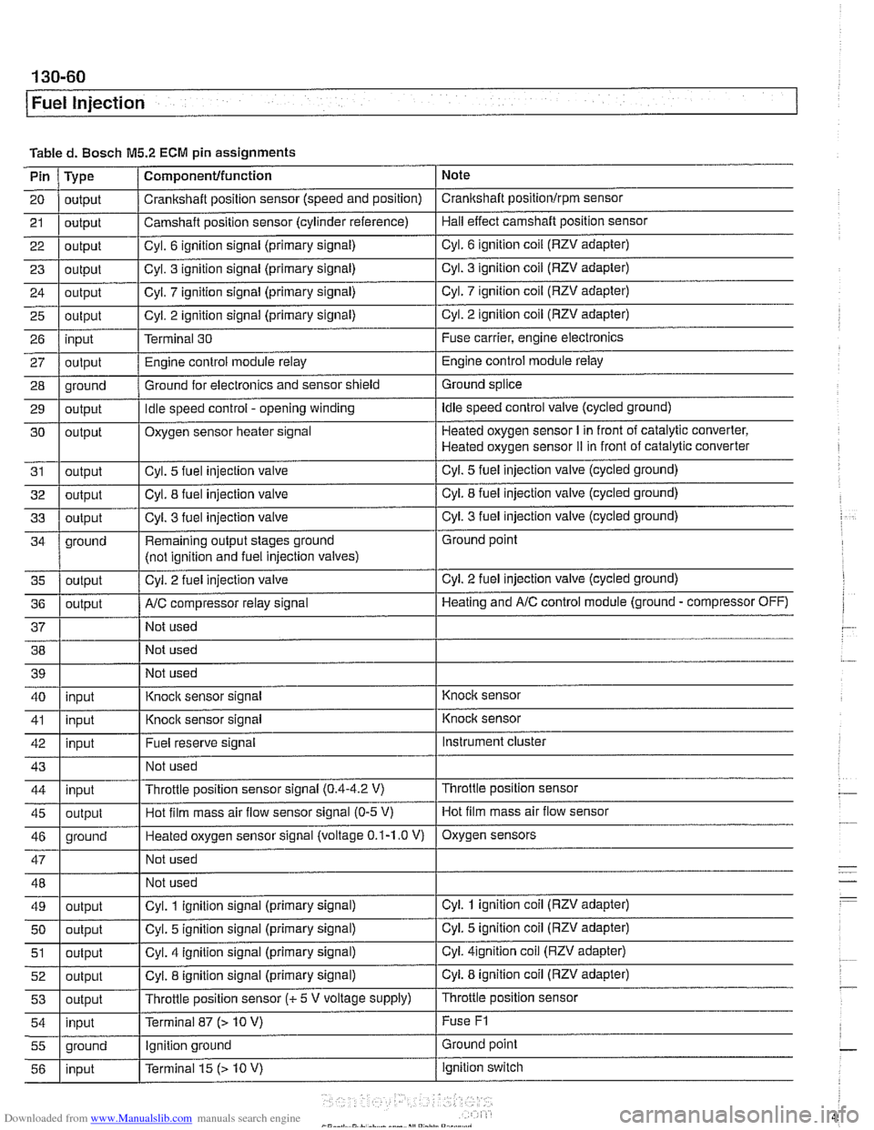
Tabled. Bosch M5.2 ECM pin assignments
Note
Pin
21
20 I output / Crankshaft position sensor (speed and position) I Crankshaft positionlrpm sensor
23
I - I I 29 1 output I Idle speed control - opening winding I Idle speed control valve (cycled ground)
Type
22
1 output I Cvl. 6 ignition signal (primary signal) I Cyl. 6 ignition coil (RZV adapter)
output
25
26
27
28
Component/function
24 1 outout I Cvl. 7 iqnition siqnal (primary signal) I Cyl. 7 ignition coil (RZV adapter)
output
4 outbut I' I - I Cyl. 3
fuel injection valve I Cyl. 3 fuel injection valve (cycled ground)
Camshaft position
sensor (cylinder reference)
output input
output
oround
30
31
32
ground Hall effect camshaft position sensor
Cyl. 3 ignition signal (primary signal)
output
I
Cyl. 3 ignition coil (RZV adapter)
. - . .. . .
Cyl. 2 ignition signal (primary signal)
Terminal 30
Engine control module relay
Ground for electronics and sensor shield
output
output
outout
Remaining output stages ground
(not iclnition and fuel iniection valves) Cyl.
2 ignition coil (RZV adapter)
Fuse carrier, engine electronics
Engine control module relay
Ground splice ,
Cyl. 2 fuel injection valve
Oxygen sensor heater signal
Cyl. 5
fuel injection valve
Cvl. 8 fuel iniection valve
AIC comuressor relav sianal
Heated oxygen sensor I in front of catalytic converter,
Heated oxygen sensor
iI in front of catalytic converter
Cyl.
5 fuel injection valve (cycled ground)
Cvl. 8 fuel iniection valve (cycled ground)
. -
Not used Ground point
Cyl.
2 fuel injection valve (cycled ground)
Heatinq and AIC control module (ground - compressor OFF)
38 Not used
40 39
1 I Not used
I'
I . I
I' I -. I
46 1 ground I Heated oxygen sensor signal (voltage 0.1-1.0 V) I Oxygen sensors
41
1 inuut I Knock
sensor signal I Knock sensor
input
I
I I
Instrument cluster
I' I I 55 1 ground I Ignition ground I Ground point
Knock sensor signal
43
1 I Not used I
Fuel reserve signal
42
Throttle position sensor
47
48
49
50
51
52
53
54
Knoclc sensor
input
45
1 outout I Hot film mass air flow sensor signal (0-5 V) I Hot film mass air flow sensor
Throttle position sensor signal
(0.4-4.2 V) 44
input
output
output
output
output
output
inout
I - I
Not used
Not used
Cyl. 1 ignition signal (primary signal)
Cyl. 5 ignition signal (primary signal)
Cyl. 4 ignition signal (primary signal)
Cyl. 8 ignition signal (primary signal)
Throttle position sensor
(c 5 V voltage supply)
Terminal 87
f> 10 V)
ignition switch
56
Cyl. 1 ignition coil (RZV adapter)
Cyi. 5 ignition coil (RZV adapter)
Cyi.
4ignition coil (RZV adapter)
Cyl. 8 ignition coil (RZV adapter)
Throttle position sensor
Fuse
F1
input Terminal 15 (> 10 V)
Page 625 of 1002
Downloaded from www.Manualslib.com manuals search engine
300-5
Suspension, Steering and Brakes - ~enerall
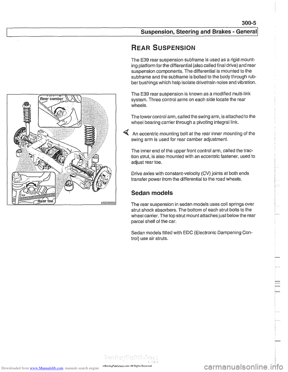
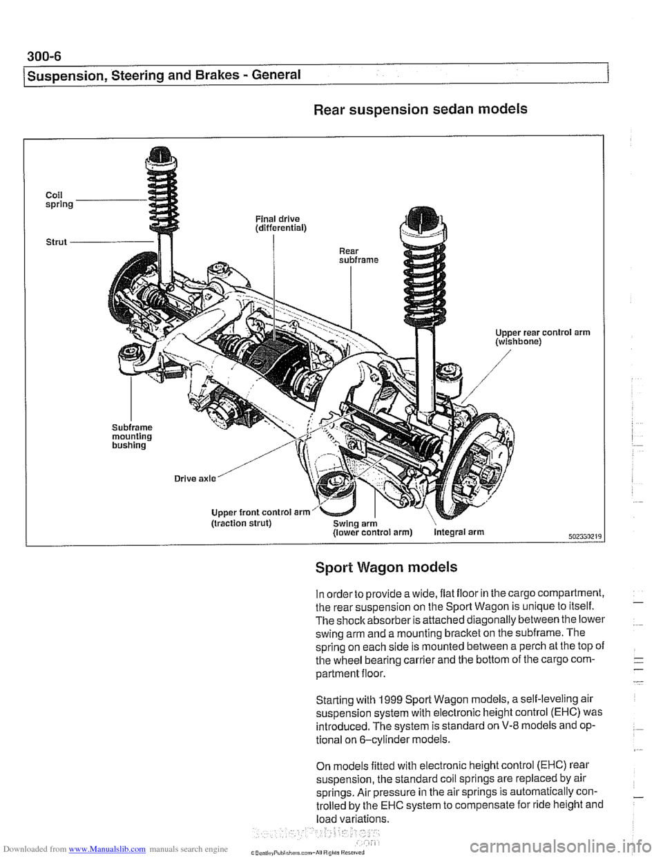
The E39 rear suspension subframe is used as a rigid mount-
ing platform
forthe differential (also called final drive) and rear
suspension components. The differential is mounted to the
subframe and the subframe is bolted to the body through rub-
ber bushings which help isolate drivetrain noise and vibration.
The
€39 rear suspension is known as a modified multi-link
system. Three control arms on each side locate the rear
wheels.
The lowercontrol arm, called the swing arm, is attached to the
wheel bearing carrier through a pivoting integral link.
An eccentric mounting bolt at the rear inner mounting of the
swing arm is used for rear camber adjustment.
The inner end of the upper front control arm, called the trac-
tion strut, is also mounted with an eccentric fastener, used to
adjust rear toe.
Drive axles with constant-velocity (CV) joints at both ends
transfer power
from the differential to the road wheels.
Sedan models
The rear suspension in sedan models uses coil springs over
strut shock absorbers. The bottom of each strut bolts to the
wheel
carrier.The top strut mount attaches just below the rear
parcel shelf of the car.
Sedan models fitted with EDC (Electronic Dampening Con-
trol) use air struts.
Page 626 of 1002
Downloaded from www.Manualslib.com manuals search engine
300-6
/Suspension, Steering and Brakes - General
Rear suspension sedan models
Coil spring
Strut
-
'01 arm
Sport Wagon models
In order to provide a wide, ilat iloor in the cargo compartment,
the rear suspension on the Sport Wagon is unique to itself.
The shoclcabsorber is attached diagonally between the lower
swing arm and a mounting bracket on the subframe. The
spring on each side is mounted between a perch at the top
oi
the wheel bearing carrier and the bottom of the cargo com-
partment floor.
Starting with
1999 Sporl Wagon models, a self-leveling air
suspension system with electronic height control (EHC) was introduced. The system is standard on
V-8 models and op-
tional on 6-cylinder models.
On models fitted with electronic height control (EHC) rear
suspension, the standard coil springs are replaced by air
springs. Air pressure in the air springs is automatically con-
trolled by the
EHC system to compensate for ride height and
load variations.