CARRIER BMW 540i 1997 E39 Workshop Manual
[x] Cancel search | Manufacturer: BMW, Model Year: 1997, Model line: 540i, Model: BMW 540i 1997 E39Pages: 1002
Page 134 of 1002
Downloaded from www.Manualslib.com manuals search engine
11 3-40
I Cylinder Head Removal and Installation
Lubricate camshafts, camshaft carriers, bearing caps, hy-
draulic lifters, friction washers, splined shafts and spline hubs
with assembly lubricant before installation.
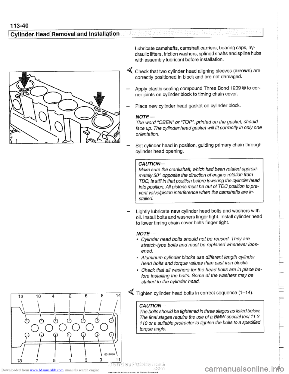
4 Check that two cylinder head aligning sleeves (arrows) are
correctly positioned in block and are not damaged.
- Apply elastic sealing compound Three Bond 1209 8 to cor-
ner joints on cylinder block to timing chain cover.
- Place new cylinder head gasket on cylinder block.
NOTE-
The word "OBEN" or "TOP printed on the gasket, should
face up. The cylinder headgaslet will fit correctly in only one
orientation.
- Set cylinder head in position, guiding primary chain through
cylinder head opening.
CAUJION-
Make sure the crankshaft, which had been rotated approxi-
mately 30" opposite the direction of engine rotation from
TDC, is still in thatposition before lowering the cylinder head
into position. All pistons must be out of TDC position to pre-
vent
valve/piston interference when the camshafts are in-
stalled.
- Lightly lubricate new cylinder head bolts and washers with
oil. Install bolts and washers finger tight. Install cylinder head
to lower timing chain cover bolts finger tight.
NOJE-
Cylinder head bolts should not be reused. They are
stretch-type bolts and must be replaced whenever loos-
ened.
* Aluminum cylinder blocls use different length cylinder
head bolts and torque values than cast iron blocks.
Check that all washers for
Nle head bolts are in place be-
fore installing the bolts. Some of the washers may be
staked to the cylinder head.
I 12 10 4 2 6 8 141 Tighten cylinder head bolts in correct sequence (1-14)
CA U TIOW-
The bolts should be tightened in three stages as listed below
The final stages require the use of a BMW special tool
11 2
110 or a suitable protractor to tighten the bolts to a specified
torque angle.
Page 136 of 1002
Downloaded from www.Manualslib.com manuals search engine
1 13-42
I Cylinder Head Removal and Installation
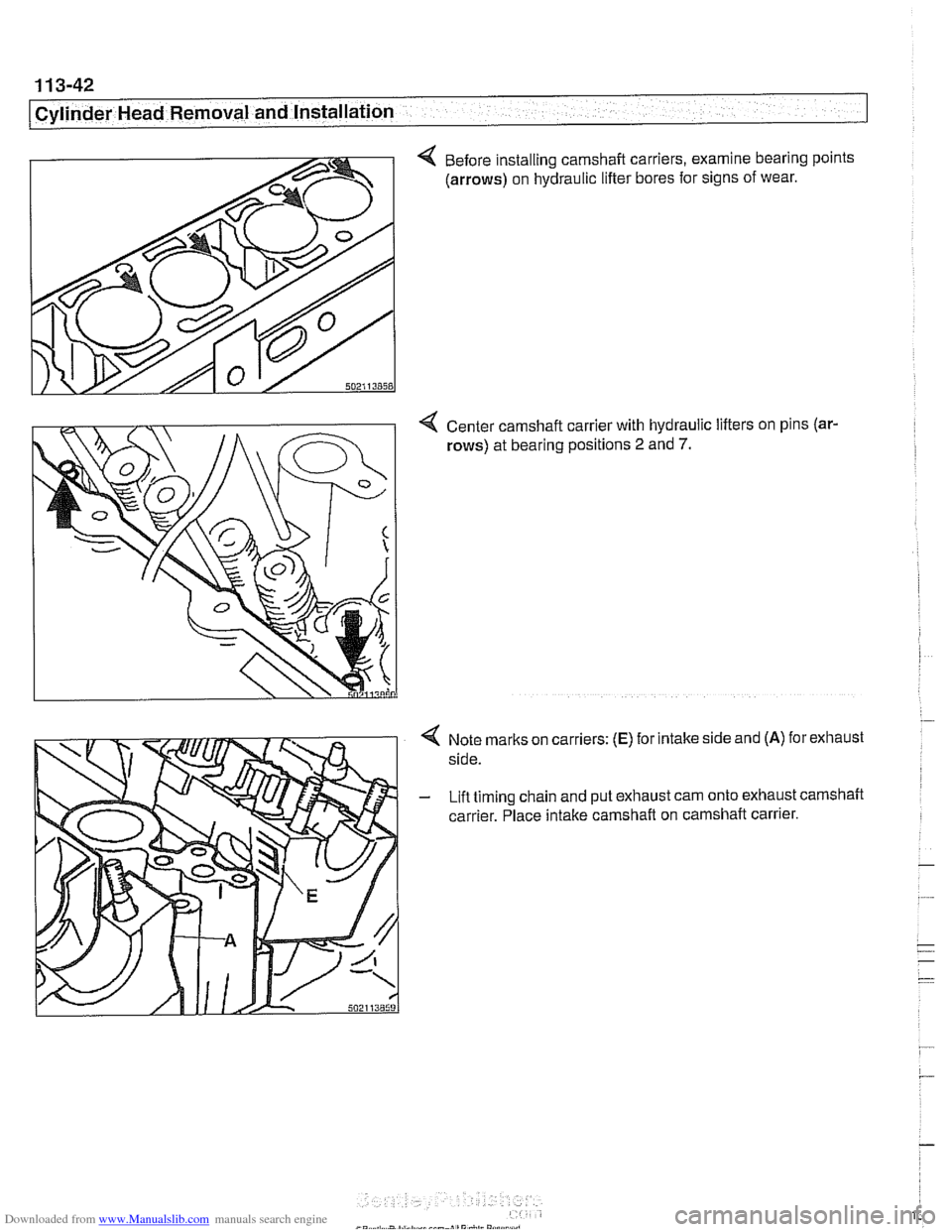
4 Before installing camshaft carriers, examine bearing points
(arrows) on hydraulic lifter bores for signs of wear.
4 Center camshaft carrier with hydraulic lifters on pins (ar-
rows) at bearing positions 2 and 7.
Note marks on carriers: (E) for intake side and (A) for exhaust
side.
Lift timing chain and put exhaust cam onto exhaust camshaft
carrier. Place intake camshaft on camshaft carrier.
Page 181 of 1002
Downloaded from www.Manualslib.com manuals search engine
11 6-5
I Cylinder Head and valvetrain1
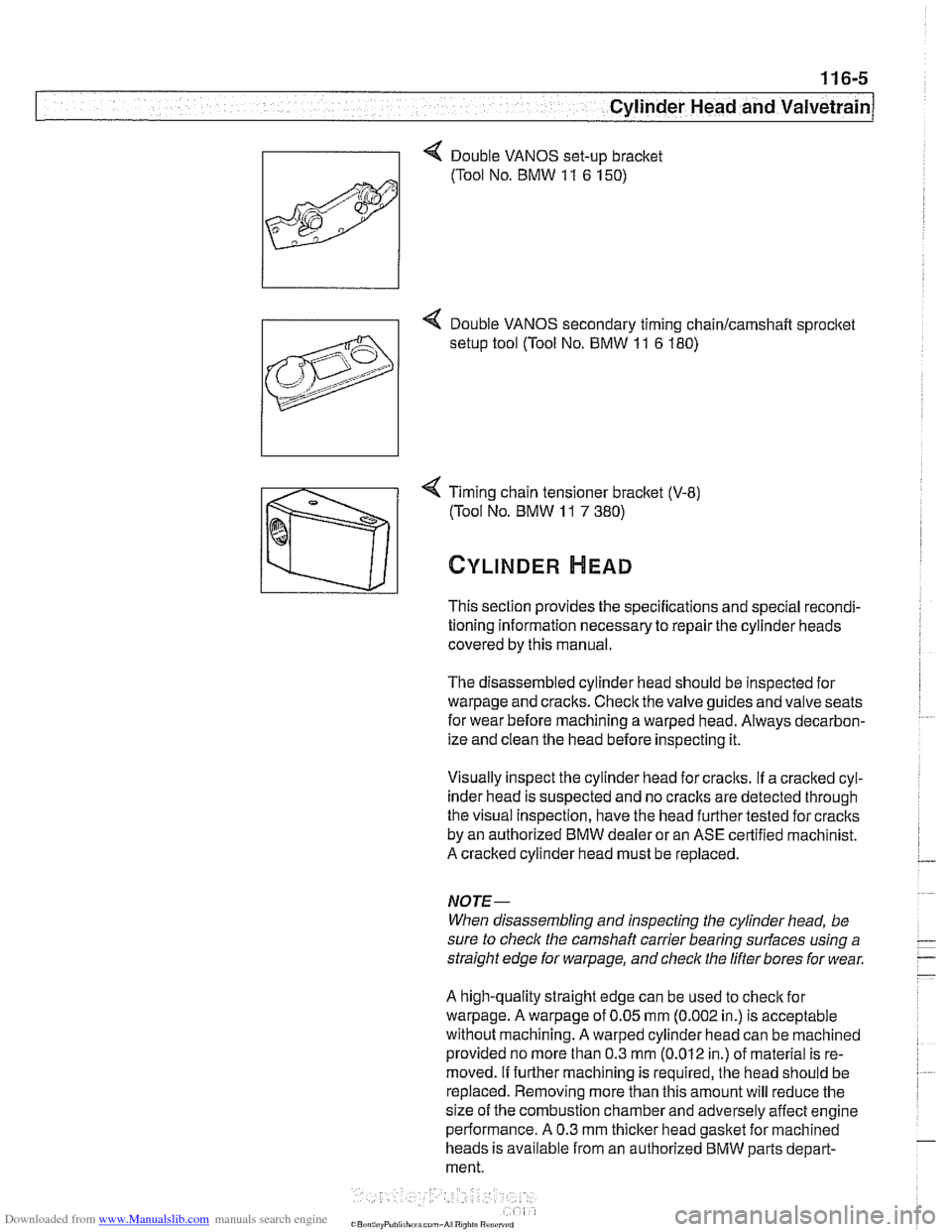
4 Timing chain tensioner bracket (V-8)
(Tool No. BMW
11 7 380)
CYLINDER HEAD
This section provides the specifications and special recondi-
tioning information necessary to repair the cylinder heads
covered by this manual.
The disassembled cylinder head should be inspected for
warpage and cracks. Check the valve guides and valve seats
for wear before machining a warped head. Always decarbon-
ize and clean the head before inspecting it.
Visually inspect the cylinder head for craclts.
If a cracked cyl-
inder head is suspected and no
craclts are detected through
the visual Inspection, have the head further tested for cracks
by an authorized BMW dealer or an ASE certified machinist.
A cracked cylinder head must be replaced.
NOJE-
When disassembling and inspecting the cylinder head, be
sure to
checlc the camshaft carrier bearing surfaces using a
straight edge for
warpage, and check the lifter bores for wear.
A high-quality straight edge can be used to
checlc for
warpage. A warpage of 0.05 mm (0.002 in.) is acceptable
without machining. A warped cylinder head can be machined
provided no more than 0.3
mm (0.012 in.) of material is re-
moved.
If further machining is required, the head should be
replaced. Removing more than this amount will reduce the
size of the combustion chamber and adversely affect engine
performance. A 0.3 mm
thicker head gasket for machined
heads is available from an authorized BMW parts depart-
ment.
Page 182 of 1002
Downloaded from www.Manualslib.com manuals search engine
11 6-6
Cylinder Head and Valvetrain
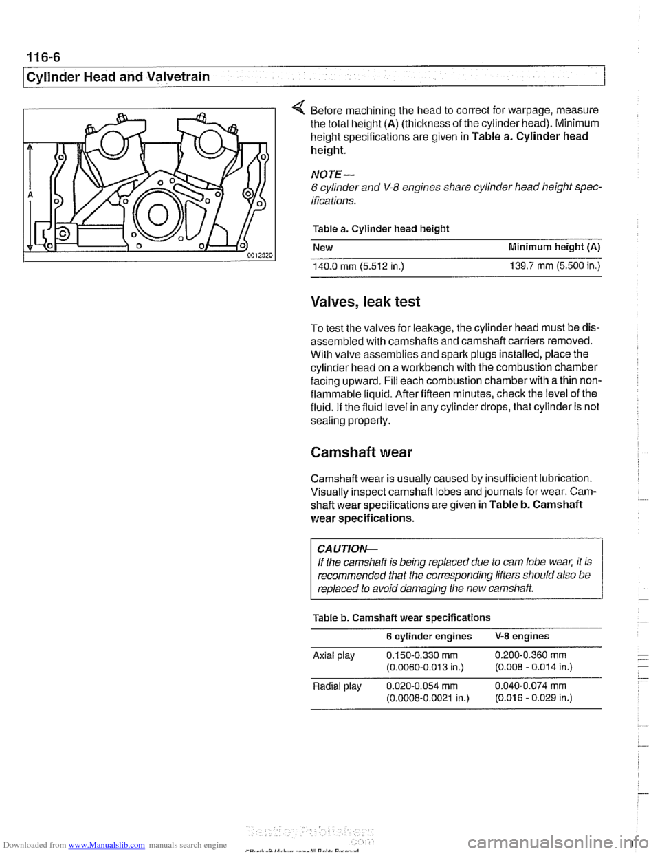
4 Before machining the head to correct for warpage, measure
the total height
(A) (thickness of the cylinder head). Minimum
height specifications are given in Table a. Cylinder head
height.
NOTE-
6 cylinder and V-8 engines share cylinder head height spec-
ifications.
Table a. Cylinder head height
New Minimum height
(A)
140.0 rnrn (5.512 in.) 139.7 rnrn (5.500 in.)
Valves, leak test
To test the valves for leakage, the cylinder head must be dis-
assembled with camshafts and camshaft carriers removed.
With valve assemblies and spark plugs installed, place the
cylinder head on a workbench with the combustion chamber
facing upward. Fill each combustion chamber with a thin non-
flammable liquid. After fifteen minutes, check the level of the
fluid. If the fluid level in any cylinder drops, that cylinder is not
sealing properly.
Camshaft wear
Camshaft wear is usually caused by insufficient lubrication.
Visually inspect camshaft lobes and journals for wear. Cam-
. ~~ shaft wear specifications are given in Table b. Camshaft
wear specifications.
CA UTIOI\C
If the camshaft is being replaced due to cam lobe wear, it is
recommended that the corresponding lifters should also be
replaced to avoid damaging the new camshaft
Table b. Camshaft wear specifications
6 cylinder engines V-8 engines
Axlal play 0.150-0.330 rnrn 0 200-0 360 rnrn - .-
(0.0060-0 013 in.) (0.008 - 0.014 in ) - - Radlal play 0.020-0.054 rnrn 0.040-0.074 rnrn
(0.0008-0.0021 in.) (0.016 - 0.029 in.)
Page 193 of 1002

Downloaded from www.Manualslib.com manuals search engine
Cylinder Head and Valvetrain
4 Secure hydraulic lifters in lifter bores using BMW special tool
11 3 250, or remove lifters using a magnetic pick-up tool.
4 Remove camshaft bearing carrier from cylinder head.
CA UTION-
Camshaftbearing carriers must be reinstalledin their original
/ locations (E for ir;fal
Do not let hydraulic lifters fall out as the camshaft carrier is
removed.
Hydraulic lifters should be stored in an upright position.
Used hydraulic lifters
must be replaced into original lifter
bores.
Camshafts and lifters, installing
(M52 Engine)
Lubricate camshafts, camshaft carriers, bearing caps, hy-
draulic liflers, friction washers, splined shafts and spline hubs
with assembly lubricant before installation.
Make sure
the cranltshaft, which had been rotated approxi-
mately
30" opposite the direction of engine rotation from
TDC, is still in thatposition before lowering the
camshaffs into
position. All pistons must be out of TDC position to prevent
valve/piston interference when the camshalts are installed.
Before installing camshaft carriers, examine bearing bores
(arrows) on hydraulic lifter bores for signs of wear.
Page 194 of 1002
Downloaded from www.Manualslib.com manuals search engine
116-18
Cylinder Head and Valvetrain
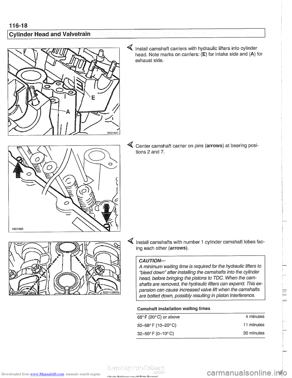
4 Install camshaft carriers with hydraulic lifters into cylinder
head. Note marks on carriers:
(E) for intake side and (A) for
exhaust side.
4 Center camshaft carrier on pins (arrows) at bearing posi-
tions
2 and 7.
4 Install camshafts with number 1 cylinder camshaft lobes fac-
ing each other (arrows).
CAUTION-
A minimum waiting time is required for the hydraulic lifters to
'bleed down" after installing the camshafts into the cylinder
head, before bringing the pistons to TDC. When the cam-
shafts are removed, the hydraulic
lifers can expand. This ex-
pansion can cause increased valve lift when the camshafts
are bolted down, possibly resulting in piston interference.
Camshaft Installation waiting
times
68" F (20" C) or above 4 minutes
50-68' F (1 0-20°C) 11 minutes
32-50" F (0-1 0" C) 30 minutes
Page 201 of 1002
Downloaded from www.Manualslib.com manuals search engine
Cylinder Head and Valvetrain
NOTE-
The camshaft bearing caps are coded with a letter and a
number. For example, "A
1" is the first exhaust camshaft
bearing cap
at the front of the engine, and "El "is the intake
camshaft bearing cap at the front of the engine.
-. -
The camshafts are stamped with a code letter - "E for the
intake side and
'X" for the exhaust side.
"E is for Einlap. (German for intake) and 'XA7s for Auspuff.
(German for exhaust).
- Repeat procedure for exhaust camshaft
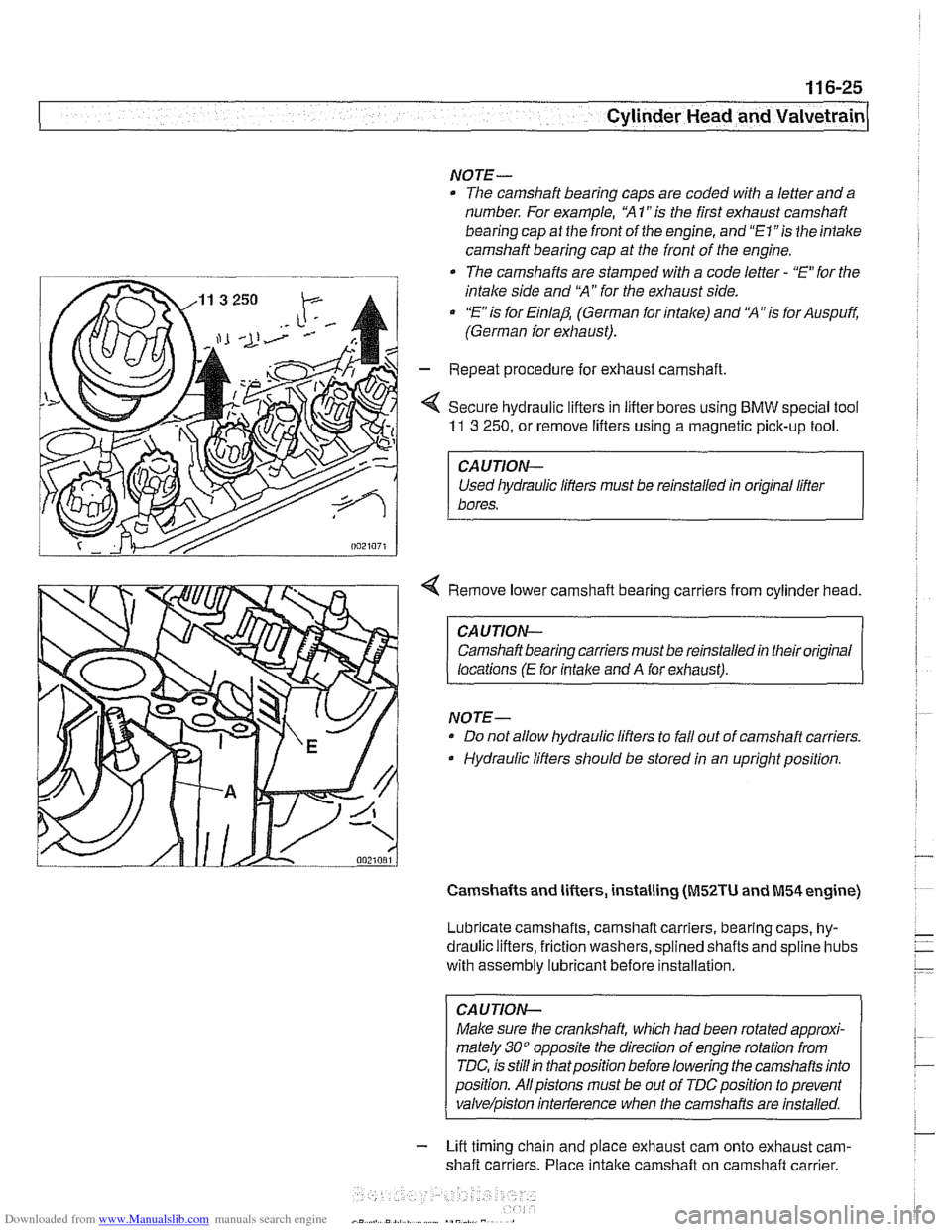
< Secure hydraulic lifters in lifter bores using BMW special tool
11 3 250, or remove lifters using a magnetic pick-up tool.
I CAUTION-
Used liydraulic lifters must be reinstalled in original lifter
1 bores.
4 Remove lower camshaft bearing carriers from cylinder head.
CAUTION- Camshaft bearing carriers must be reinstalled in their original
locations
(E for intalce and A for exhaust).
NOTE- Do not allow hydraulic lifters to fall out of camshaft carriers.
Hydraulic lifters should be stored in an upright position.
Camshafts and lifters, installing (M52TU and M54 engine)
Lubricate camshafts, camshaft carriers, bearing caps, hy-
draulic lifters, friction washers, splined shafts and
spline hubs
with assembly
lubricant before installation.
CAUTION-
Make sure the crankshaft, which had been rotated approxi-
mately
30" opposite the direction of engine rotation from
TDC, is
stillin thatposition before lowering the camshafts into
position. Allpistons must be out of
TDCposition to prevent
valve/piston inteiference when the carnshafis are installed.
- Lift timing chain and place exhaust cam onto exhaust cam-
shaft carriers. Place
intake camshaft on camshaft carrier.
Page 202 of 1002
Downloaded from www.Manualslib.com manuals search engine
11 6-26
I Cylinder Head and Valvetrain
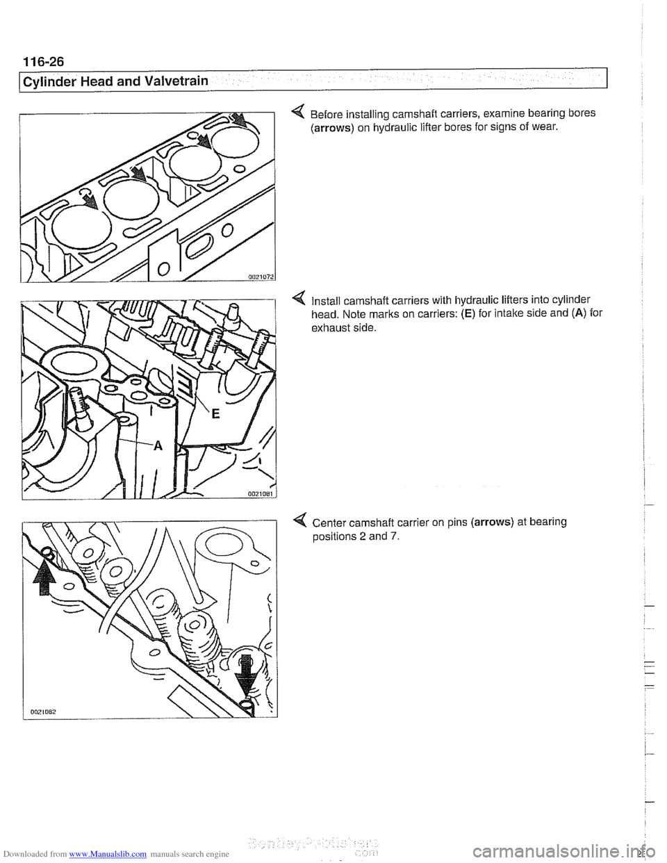
4 Before installing camshaft carriers, examine bearing bores
(arrows) on hydraulic lifter bores for signs of wear.
Install camshaft carriers with hydraulic lifters into cylinder
head. Note marks on carriers:
(E) for intake side and (A) for
exhaust side.
4 Center camshaft carrier on pins (arrows) at bearing
aositions 2 and 7.
Page 232 of 1002
Downloaded from www.Manualslib.com manuals search engine
1 16-56
Cylinder Head and Valvetrain
This section covers valve removal and reconditioning, includ-
ing valve guides, seats, springs, and valve stem oil seals.
Valves, leak test
To test the valves for leakage, the cylinder head must be dis-
assembled with camshafts and camshaft carriers removed.
With valve assemblies and spark plugs installed, place the
cylinder head on a workbench with the combustion chamber
facing upward. Fill each combustion chamber with a thin non-
flammable liquid. After fifteen minutes,
check the level of the
fluid. If the fluid level in any cylinder drops, that cylinder is not
sealing properly.
Valves, removing and installing
- Remove cylinder head as described in 113 Cylinder Head
Removal and Installation.
CAUTIOI\C
(M52 TU/M54 engines only) Do not let the hydraulic lifters
fall out as the camshaft carrier is removed. Special suction
cups are available from
BMW to hold the hydraulic lifters in
place during carrier removal.
* Hydraulic cam lifters should be stored m an uprfght po-
sition. If necessary, use a magnetic tool to
aidin remov-
al of the lifters.
- Remove valves using a valve spring compressor.
CAUTIOI\C
Label each valve assembly as it is removed so it can be in-
stalled in its original position.
-
- Remove and discard valve stem oil seals from valve guides.
See Valve stem oil seals later in this section.
- Valve installation is reverse of removal. Remove carbon de- - -
posits from the valves using a wire brush or wire wheel. -
-
Valve specifications are listed in Table c. Valve specifica-
tions.
Page 326 of 1002
Downloaded from www.Manualslib.com manuals search engine
Lubrication System
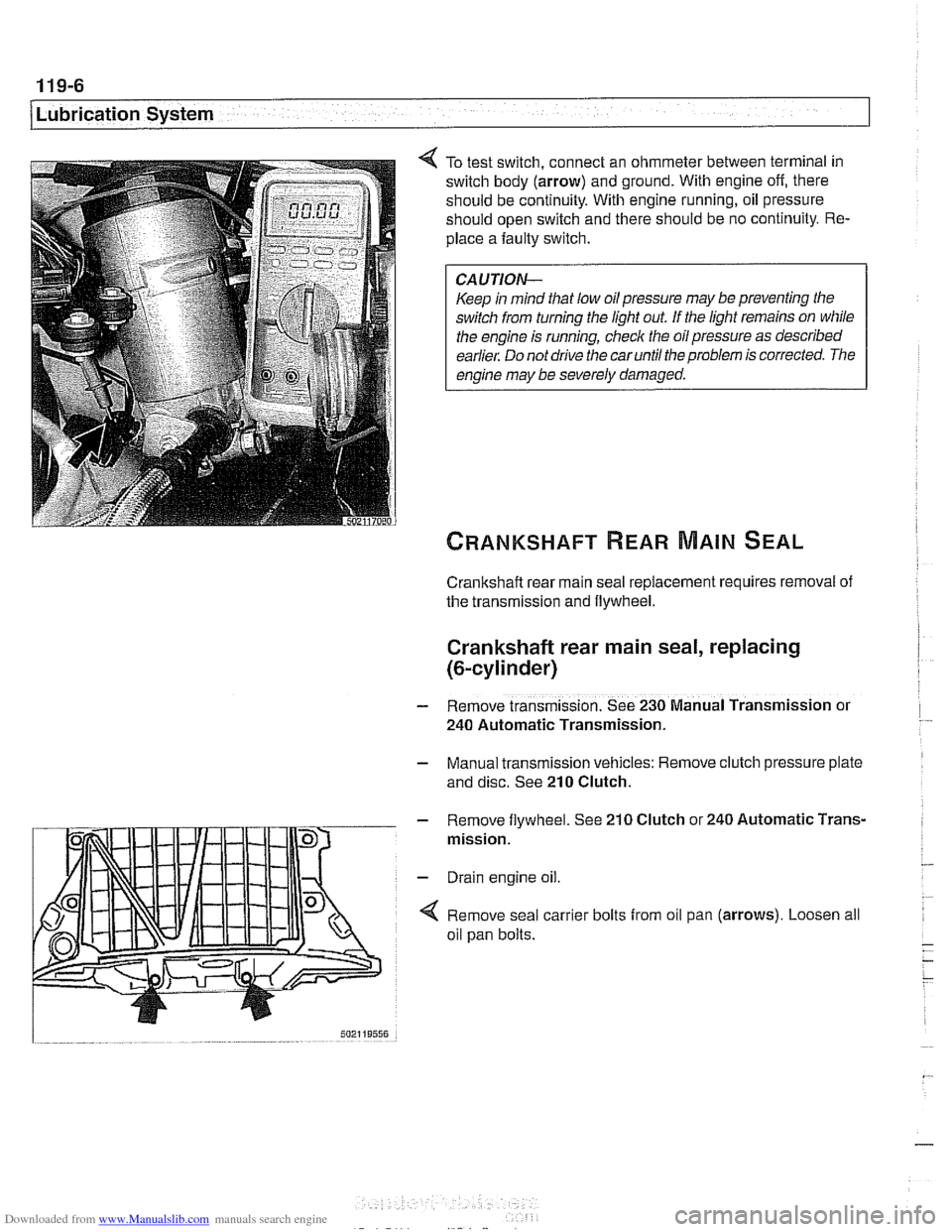
To test switch, connect an ohmmeter between terminal in
switch body (arrow) and ground. With engine off, there
should be continuity. With engine running, oil pressure
should open switch and there should be no continuity. Re-
place a faulty switch.
CAUTION-
Keep in mind that low oil pressure may be preventing the
switch from turning the light out
If the light remains on while
the engine is running, check the oil pressure as described
earlier. Do not drive the car until the problem is corrected. The
engine may be severely damaged.
Crankshaft rear main seal replacement requires removal of
the transmission and flywheel.
Crankshaft rear main seal, replacing
(&cylinder)
- Remove transmission. See 230 Manual Transmission or
240 Automatic Transmission.
- Manual transmission vehicles: Remove clutch pressure plate
and disc. See
210 Clutch.
- Remove flywheel. See 210 Clutch or 240 Automatic Trans-
mission.
- Drain engine oil.
4 Remove seal carrier bolts from oil pan (arrows). Loosen all
oil pan bolts.