Wir BMW 540i 1997 E39 User Guide
[x] Cancel search | Manufacturer: BMW, Model Year: 1997, Model line: 540i, Model: BMW 540i 1997 E39Pages: 1002
Page 69 of 1002
Downloaded from www.Manualslib.com manuals search engine
Engine identifying features
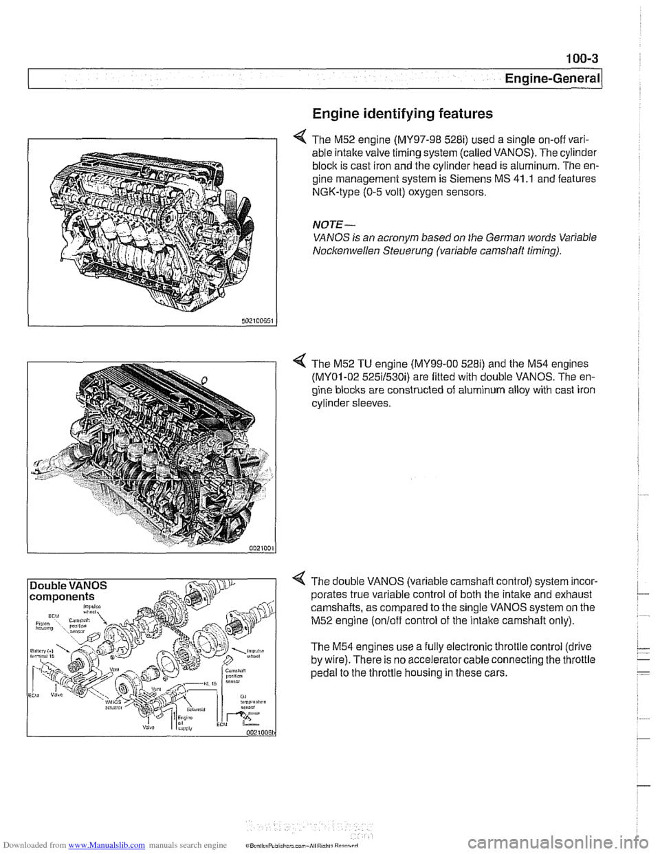
4 The M52 engine (MY97-98 528i) used a single on-off vari-
able intake valve timing system (called VANOS). The cylinder
block is cast iron and the cylinder head is aluminum. The en-
gine management system is Siemens MS 41
.I and features
NGK-type (0-5 volt) oxygen sensors.
NOTE-
VANOS is an acronym based on the German words Variable
Nocltenwellen Steuerung (variable camshaft timing).
4 The M52 TU engine (MY99-00 5281) and the M54 engines
(MY01-02 525il530i) are fitted with double VANOS. The en-
gine
blocits are constructed of aluminum alloy with cast iron
cylinder sleeves.
4 The double VANOS (variable camshaft control) system incor-
porates true variable control of both the
intake and exhaust
camshafts, as compared to the single VANOS system on the
M52 engine
(onloff control of the intaite camshaft only).
The M54 engines use a fully electronic throttle control (drive
by wire). There is no accelerator cable connecting the throttle
pedal to the throttle housing in these cars.
Page 71 of 1002
Downloaded from www.Manualslib.com manuals search engine
Two common causes of driveability problems are incorrect
system voltage and bad grounds.
System voltage
Digital motor electronics (DME) requires that the system (bat-
tery) voltage be maintained within a narrow range of DC volt-
age.
DC voltage levels beyond or below the operating range,
or any
AIC voltage in the electrical system can cause havoc.
When troubleshooting an illuminated MIL, make sure the bat-
tery is fully charged and capable of delivering all its power to
the electrical system. An undercharged battery can amplify
AIC alternator output ripple.
To
make a quick check of the battery charge, measure the
voltage across the battery terminals with all cables attached
and the ignition off.
Afully charged battery will measure 12.6
volts or slightly more, compared to 12.1 5 volts for a battery
with a 25% charge.
The DME system operates at low voltage and current levels,
making it sensitive to small increases in resistance. The elec-
trical system is routinely subjected to corrosion, vibration and
wear, so faults or corrosion in the wiring harness and connec-
tors are not uncommon. Check the battery terminals
forcorro-
sion or loose cable connections. See 121 Battery, Starter,
Alternator for additional information.
If a battery cable connection has no
v~sible faults but is still
suspect, measure the voltage drop across the connection. A
large drop indicates excessive resistance, meaning that the
connection is corroded, dirty, or damaged. Clean or repairthe
connection and retest.
NOTE-
For instructions on conducting a voltage drop test and other
general electrical troubleshooting information, see
600 Elec-
trical System-General.
Visually inspect all wiring, connectors, switches and fuses in
the system. Loose or damaged connectors can cause inter-
mittent problems, especially the small terminals in the ECM
connectors. Disconnect the wiring harness connectors to
check for corrosion, and use electrical cleaning spray to re-
move contaminants.
Main grounds
Good grounds are critical to proper DME operation. If a
ground connection has no visible faults but is still suspect.
measure the voltage drop across the connection. A large volt-
age drop means high resistance. Clean or repair the connec-
tion and retest.
LBuntr.yP~sbhnllcn.can#-AII A,~iltl Rcsrwsd
Page 75 of 1002
Downloaded from www.Manualslib.com manuals search engine
110-3
Engine Removal and lnstallationl
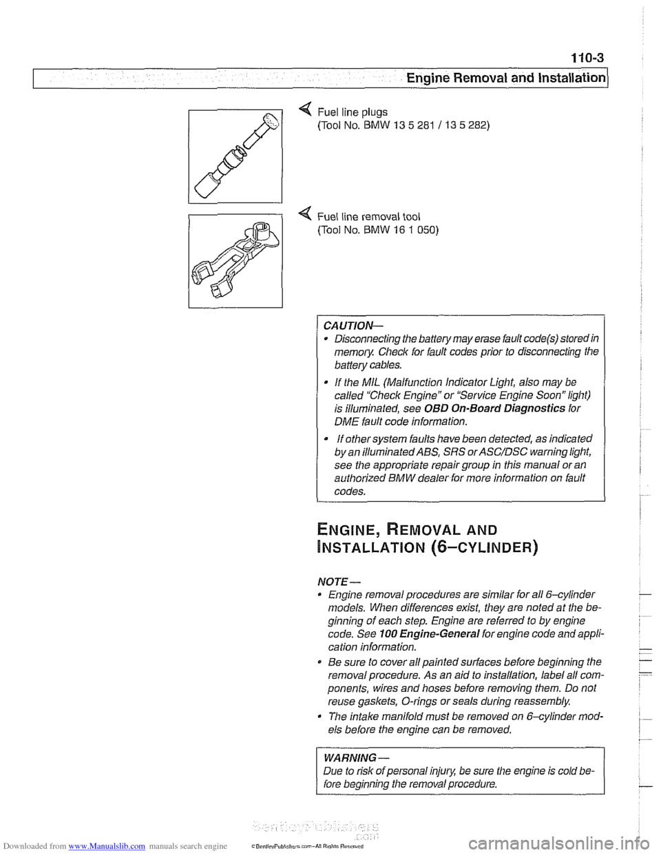
Q Fuel line plugs
(Tool No.
BMW 13 5 281 / 13 5 282)
4 Fuel line removal tool
(Tool No.
BMW 16 1 050)
CAUTION-
Disconnecting the battery may erase fault code@) storedin
memoiy Check for fault codes prior to disconnecting the
battery cables.
If the MIL (Malfunction Indicator Light, also may be
called "Check Engine" or "Service Engine Soon" light)
is illuminated, see
OBD On-Board Diagnostics for
DME fault code information.
It orhersysrem faults have been detected, as indicated I
by an ~llum~nated ABS, SRS orASC/DSC ~arning light,
see the appropriate repair group in this manual or an
authorized BMW dealer for more information on fault
codes.
NOTE- Engine removal procedures are similar for all 6-cylinder
models. When differences
exist, they are noted at the be-
ginning of each step. Engine are referred to by engine
code. See
100 Engine-General for engine code and appli-
cation information.
@ Be sure to cover all painted surfaces before beginning the
removal procedure. As an aid to installation, label all com-
ponents, wires and hoses before removing them. Do not
reuse
gaskets, O-rings or seals during reassembly.
The
intake manifold must be removed on &cylinder mod-
els before the engine can be removed.
WARNING-
Due to risk of personal injury, be sure the engine is cold be-
fore beginning the removal procedure.
Page 77 of 1002
Downloaded from www.Manualslib.com manuals search engine
Engine Removal and lnstallationl
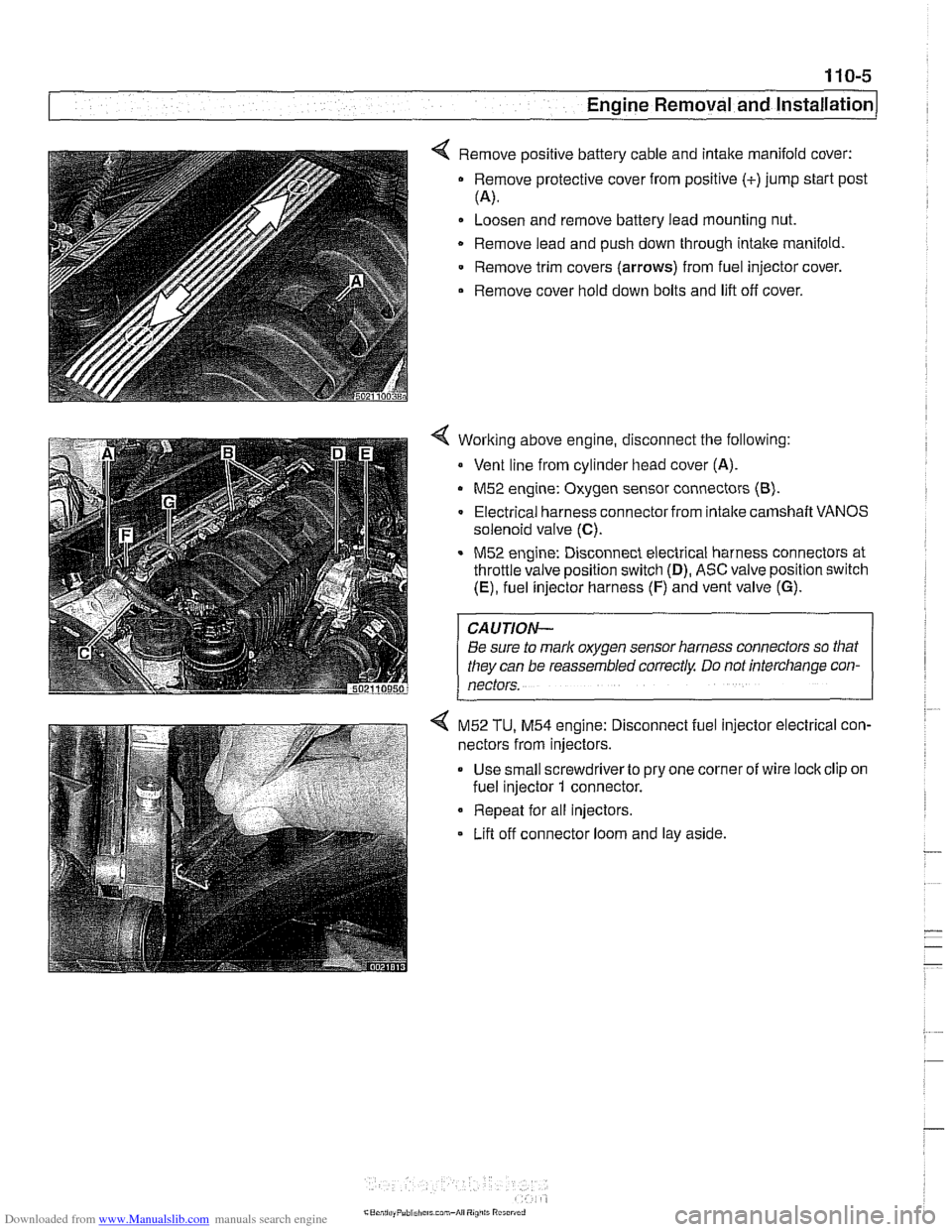
< Remove positive battery cable and intake manifold cover:
Remove protective cover from positive (+)jump start post
(4.
Loosen and remove battery lead mounting nut.
Remove lead and push down through intake manifold
Remove trim covers
(arrows) from fuel injector cover.
Remove cover hold down bolts and lift off cover.
Working above engine, disconnect the following:
Vent line from cylinder head cover (A).
M52 engine: Oxygen sensor connectors (8).
Electrical harness connector from intalte camshaft VANOS
solenoid valve
(C).
M52 engine: Disconnect electrical harness connectors at
throttle valve position switch
(D), ASC valve position switch
(E), fuel injector harness (F) and vent valve (G).
CAUTION-
Be sure to mark oxygen sensor harness connectors so that
they can be reassembled correctly Do not interchange con-
nectors.
4 M52 TU, M54 engine: Disconnect fuel injector electrical con-
nectors from injectors.
Use small screwdriverto pry one corner of wire lock clip on
fuel injector
1 connector.
Repeat for all injectors.
Lifl off connector loom and lay aside.
Page 80 of 1002
Downloaded from www.Manualslib.com manuals search engine
110-8
1 Engine Removal and Installation
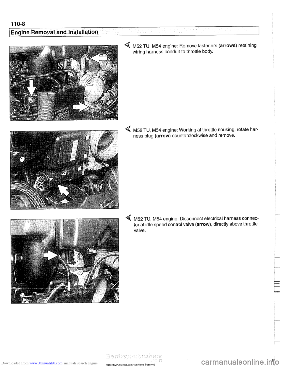
4 M52 TU, M54 engine: Remove fasteners (arrows) retaining
wiring harness conduit to throttle body.
4 M52 TU, M54 engine: Working at throttle housing, rotate har-
ness plug (arrow) counterclockwise and remove.
4 M52 TU, M54 engine: Disconnect electrical harness connec-
tor at idle speed control valve (arrow), directly above throttle
valve.
Page 84 of 1002
Downloaded from www.Manualslib.com manuals search engine
110-12
Engine Removal and Installation
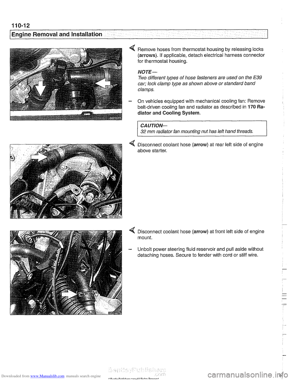
4 Remove hoses from thermostat housing by releasing locks
(arrows). If applicable, detach electrical harness connector
for thermostat housing.
NOTE-
Two different types of hose fasteners are used on the E39
car; lock clamp type as shown above or standard band
clamps.
- On vehicles equipped with mechanical cooling fan: Remove
belt-driven cooling fan and radiator as described in
170 Ra-
diator and Cooling
System.
CAUTION-
32 mm radiator fan mounting nut has left hand threads.
4 Disconnect coolant hose (arrow) at rear left side of engine
above starter.
4 Disconnect coolant hose (arrow) at front left side of engine
mount.
- Unbolt power steering fluid reservoir and pull aside without
detaching hoses. Secure to fender with cord or stiff wire.
Page 85 of 1002
Downloaded from www.Manualslib.com manuals search engine
Engine Removal and Installation
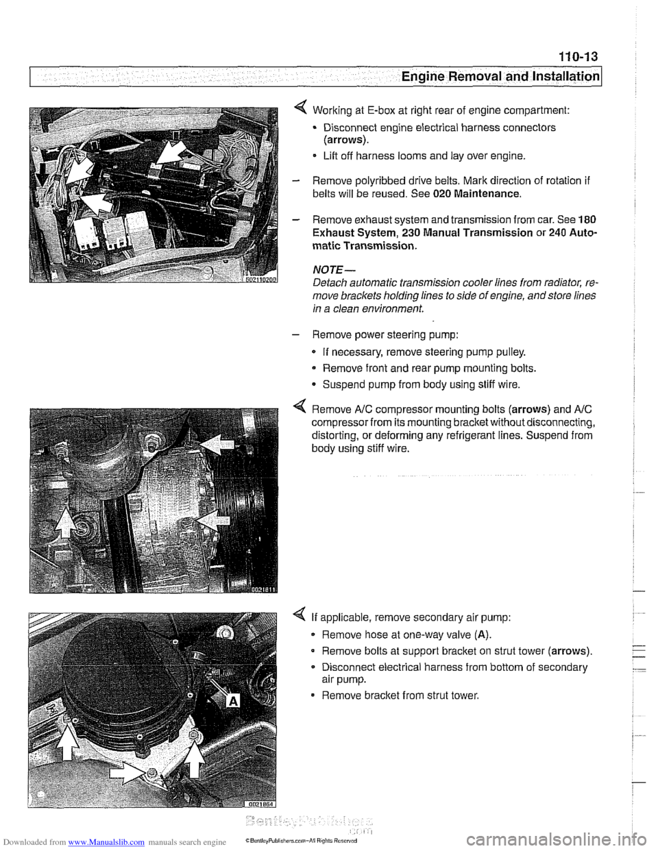
4 Working at E-box at right rear of engine compartment:
Disconnect engine electrical harness connectors
(arrows).
Lift off harness looms and lay over engine.
- Remove polyribbed drive belts. Mark direction of rotation if
belts will be reused. See 020 Maintenance.
- Remove exhaust system and transmission from car. See 180
Exhaust System, 230 Manual Transmission or 240 Auto-
matic Transmission.
NOJE-
Detach automatic transmission cooler lines from radiator, re-
move brackets holding lines to side of engine, andstore lines
in a clean environment.
- Remove power steering pump:
If necessary, remove steering pump pulley.
Remove front and rear pump mounting bolts.
Suspend pump from body using stiff wire.
4 Remove A/C compressor mounting bolts (arrows) and AIC
compressor from its mounting bracketwithoutdisconnecting,
distorting, or deforming any refrigerant lines. Suspend from
body using stiff wire.
4 If applicable, remove secondary air pump:
Remove hose at one-way valve
(A).
Remove bolts at support bracket on strut tower (arrows).
- Disconnect electrical harness from bottom of secondary
air pump.
Remove bracket from strut tower.
Page 86 of 1002
Downloaded from www.Manualslib.com manuals search engine
110-14
I Engine Removal and Installation
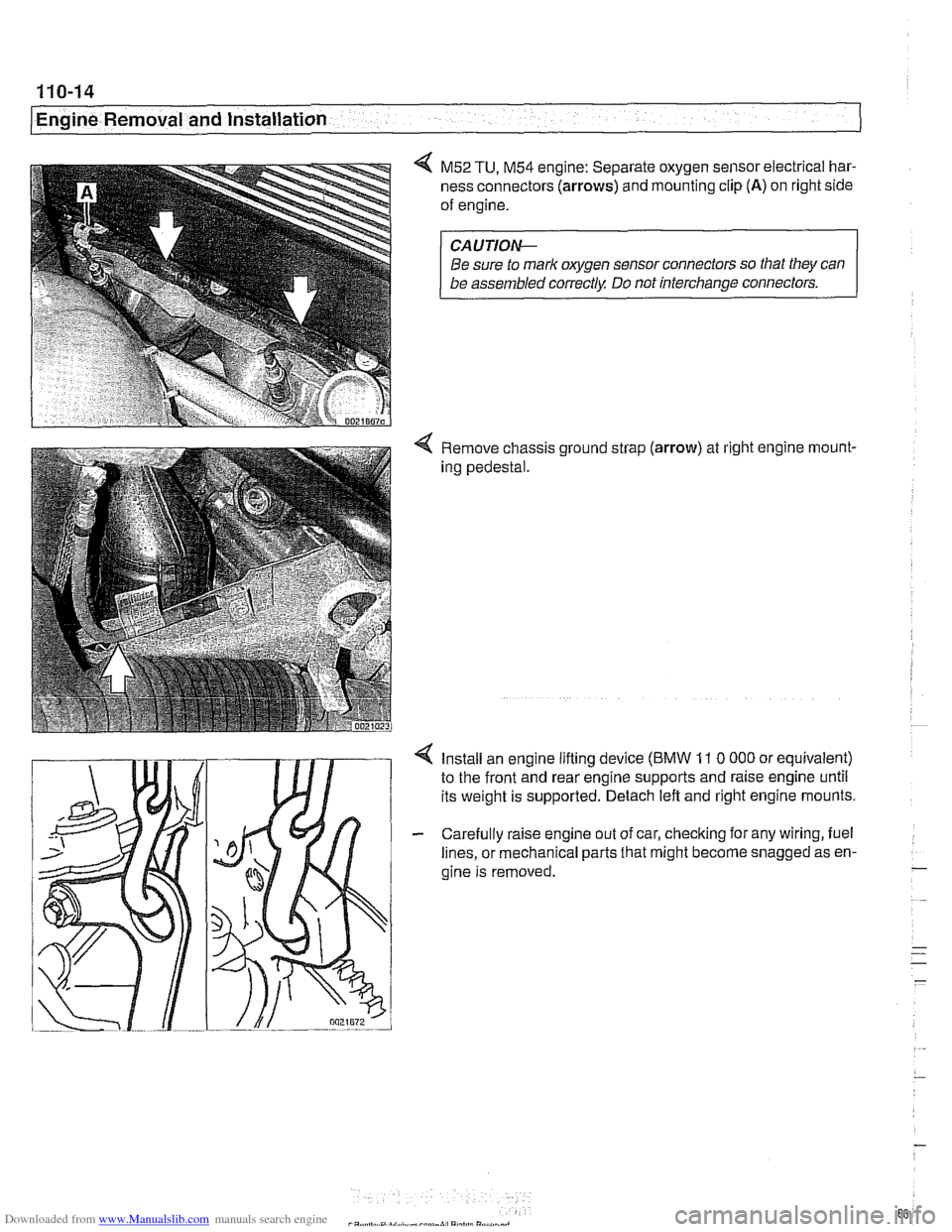
4 M52 TU, M54 engine: Separate oxygen sensor electrical har-
ness connectors
(arrows) and mounting clip (A) on right side
of engine.
CA UTIOW
Be sure to mark oxygen sensor connectors so that they can
be assembled correctly Do not interchange connectors.
4 Remove chassis ground strap (arrow) at right engine rnount-
ing pedestal.
4 Install an engine lifting device (BMW 11 0 000 or equivalent)
to the front and rear engine supports and raise engine until
its weight is supported. Detach left and right engine mounts.
- Carefully raise engine out of car, checking for any wiring, fuel
lines, or mechanical parts that might become snagged as en-
gine is removed.
-
. ..
- .- -
-
Page 88 of 1002
Downloaded from www.Manualslib.com manuals search engine
110-16
Engine Removal and Installation
ENGINE, REMOVAL AND
INSTALLATION (V-8 MODELS)
NOTE-
Engine removal procedures are similar for all V-8 models.
When differences exist, they are noted at the beginning of
each step. Engine are referred to by engine code. If neces-
sary, See
100 Engine-General for engine code andappli-
cation information.
Be sure to cover all painted surfaces before beginning the
removal procedure. As an aid to installation, label all com-
ponents, wires and hoses before removing them. Do not
reuse gaskets, O-rings or seals during reassembly
WARNING
-
Due to risk ofpersonal injury, be sure the engine is cold be-
fore beginning the
removal procedure.
- Disconnect negative (-) cable from battery.
Prior to disconnecting the battery, read the battery discon-
nection cautions given in
001 General Cautions and
Warnings.
- Remove engine hood or place hood in service position. See
410 Fenders, Engine Hood.
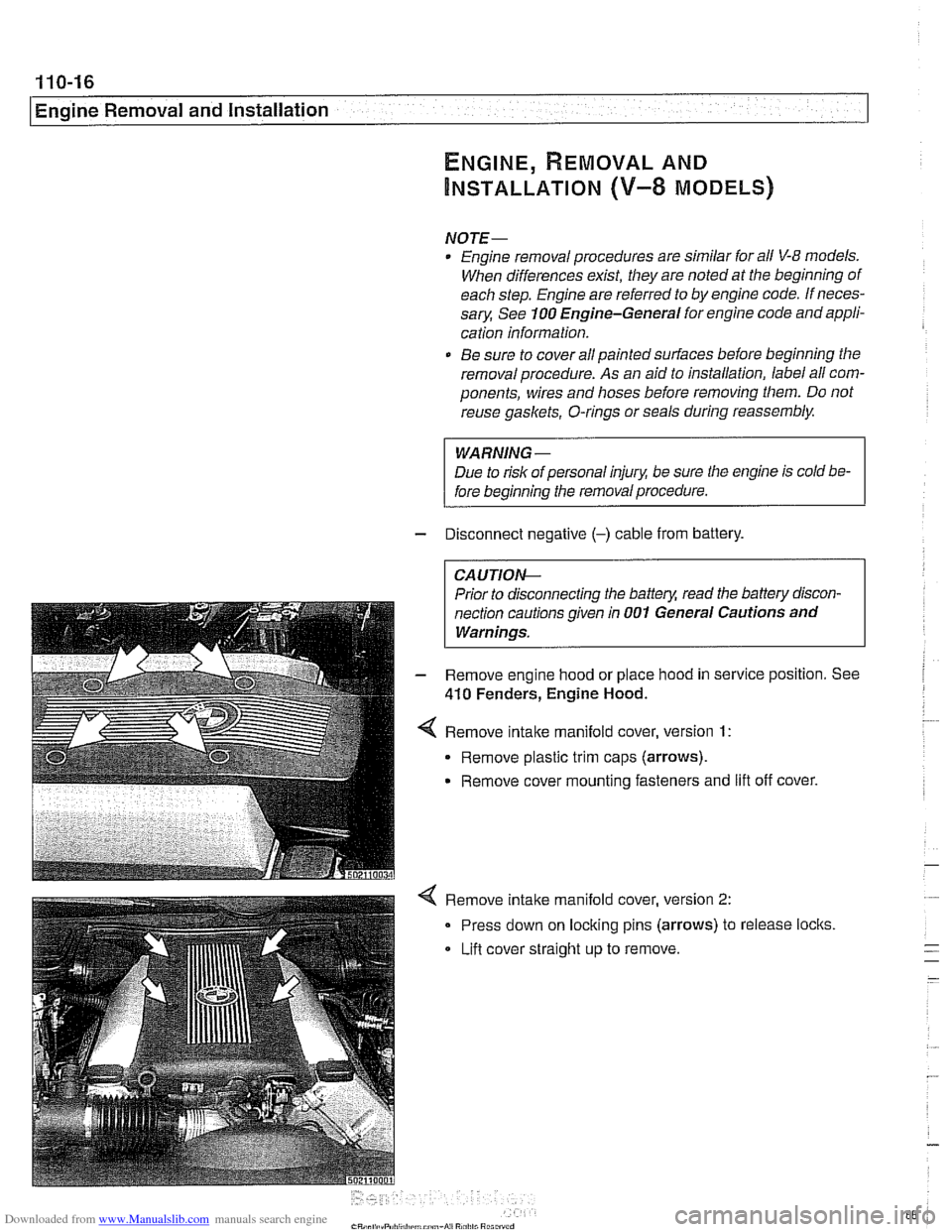
Remove
intake manifold cover, version 1:
Remove plastic trim caps (arrows).
Remove cover mounting fasteners and
lift off cover.
Remove intake manifold cover, version
2:
Press down on locking pins (arrows) to release locks
Lifl cover straight
up to remove.
Page 89 of 1002
Downloaded from www.Manualslib.com manuals search engine
- .. -.
-. Engine Removal and in=/
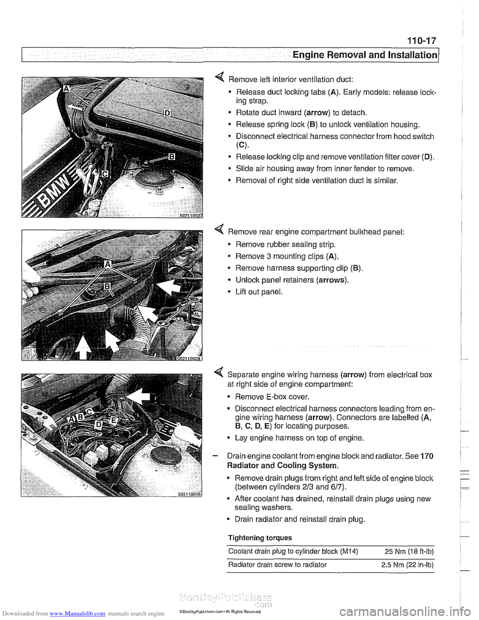
4 Remove left interior ventilation duct:
Release duct locking tabs (A). Early models: release
loclc
ing strap.
* Rotate duct inward (arrow) to detach.
Release spring
loclc (El) to unlock ventilation housing.
Disconnect electrical harness connector from hood switch
(C).
Release locking clip and remove ventilation filter cover (D).
Slide air housing away from inner fender to remove.
Removal
of right side ventilation duct is similar.
4 Remove rear engine compartment bulkhead panel:
Remove rubber sealing strip.
* Remove 3 mounting clips (A).
Remove harness supporting clip
(El).
Unlock panel retainers (arrows).
Lifl out panel.
< Separate engine wiring harness (arrow) from electrical box
at right side of engine compartment:
Remove E-box cover.
Disconnect electrical harness connectors leading from en-
gine wiring harness (arrow). Connectors are labelled (A,
El, C. D, E) for locating purposes.
Lay engine harness on top of engine.
- Drain engine coolant from engine block and radiator. See 170
Radiator and Cooling System.
Remove drain plugs from right and left side of engine
bloclc
(between cylinders 213 and 617).
Afler coolant has drained, reinstall drain plugs using new
sealing washers.
Drain radiator and reinstall drain plug.
Tightening
torques
Coolant drain plug to cylinder block (M14) 25 Nm (18 ft-ib)
Radiator drain screw to radiator 2.5
Nm (22 in-lb)