Wir BMW 540i 1997 E39 Service Manual
[x] Cancel search | Manufacturer: BMW, Model Year: 1997, Model line: 540i, Model: BMW 540i 1997 E39Pages: 1002
Page 191 of 1002
Downloaded from www.Manualslib.com manuals search engine
116-15
Cylinder Head and Valvetrain
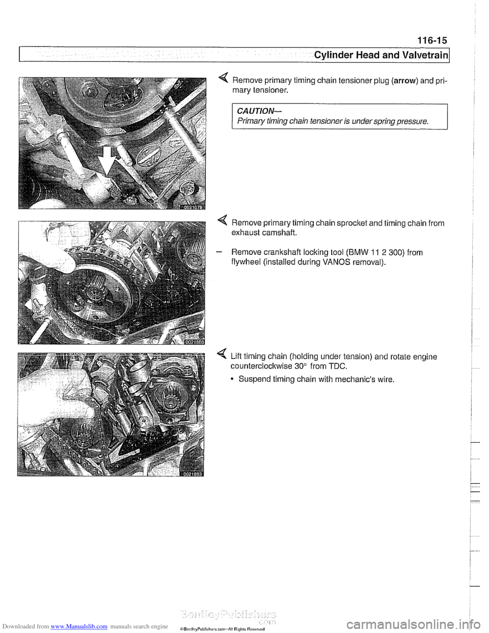
4 Remove primary timing chain tensioner plug (arrow) and pri-
mary tensioner.
CAUTION-
Primary timinq chain tensioner is under sarina aressure.
4 Remove primary timing chain sprocket and timing chain from
exhaust camshaft.
- Remove crankshaft locking tool (BMW 11 2 300) from
flywheel (installed during
VANOS removal).
Lift timing chain (holding under tension) and rotate engine
counterclockwise 30" from
TDC.
- Suspend timing chain with mechanic's wire
Page 214 of 1002
Downloaded from www.Manualslib.com manuals search engine
I Cylinder Head and Valvetrain
- Remove adjustable primary timing chain tensioner tool and
reinstall primary chain tensioner cylinder to cylinder head.
Tightening torque
Primary chain tensioner cylinder
to 70 Nm (52 ft-lb)
cylinder head
- Remove flywheel locking tool from crankcase. Replace spe-
cial tool bore sealing plug.
- Remove camshaft locking tools from cylinder head
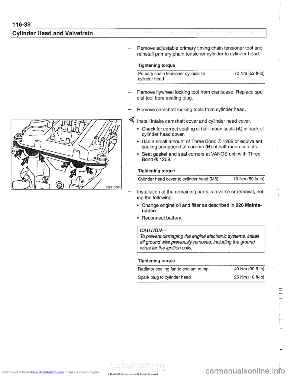
Install intake camshaft cover and cylinder head cover.
Check for correct seating of half-moon seals (A) in back of
cylinder head cover.
Use a small amount of Three Bond
8 1209 or equivalent
sealing compound at corners
(B) of half-moon cutouts.
Seat gasket and seal corners at VANOS unit with Three
Bond
@ 1209.
Tightening torque Cylinder head cover to cylinder head
(M6) 10 Nm (89 in-lb)
- Installation of the remaininq parts is reverse or removal, not- -
ing the following:
Change engine
011 and f~lter as descr~bed in 020 Mainte-
nance.
Reconnect battery.
To prevent damaging the engine electronic systems, install
all ground wire previously removed, including the ground
wires for the ignition coils.
Tightening torque
-
Radiator cooling fan to coolant pump 40 Nm
(30 ft-ib)
Spark plug to cylinder head
25 Nm (18 ft-ib)
Page 216 of 1002
Downloaded from www.Manualslib.com manuals search engine
-. .
Cylinder Head and Valvetrain -- v . -- --- --
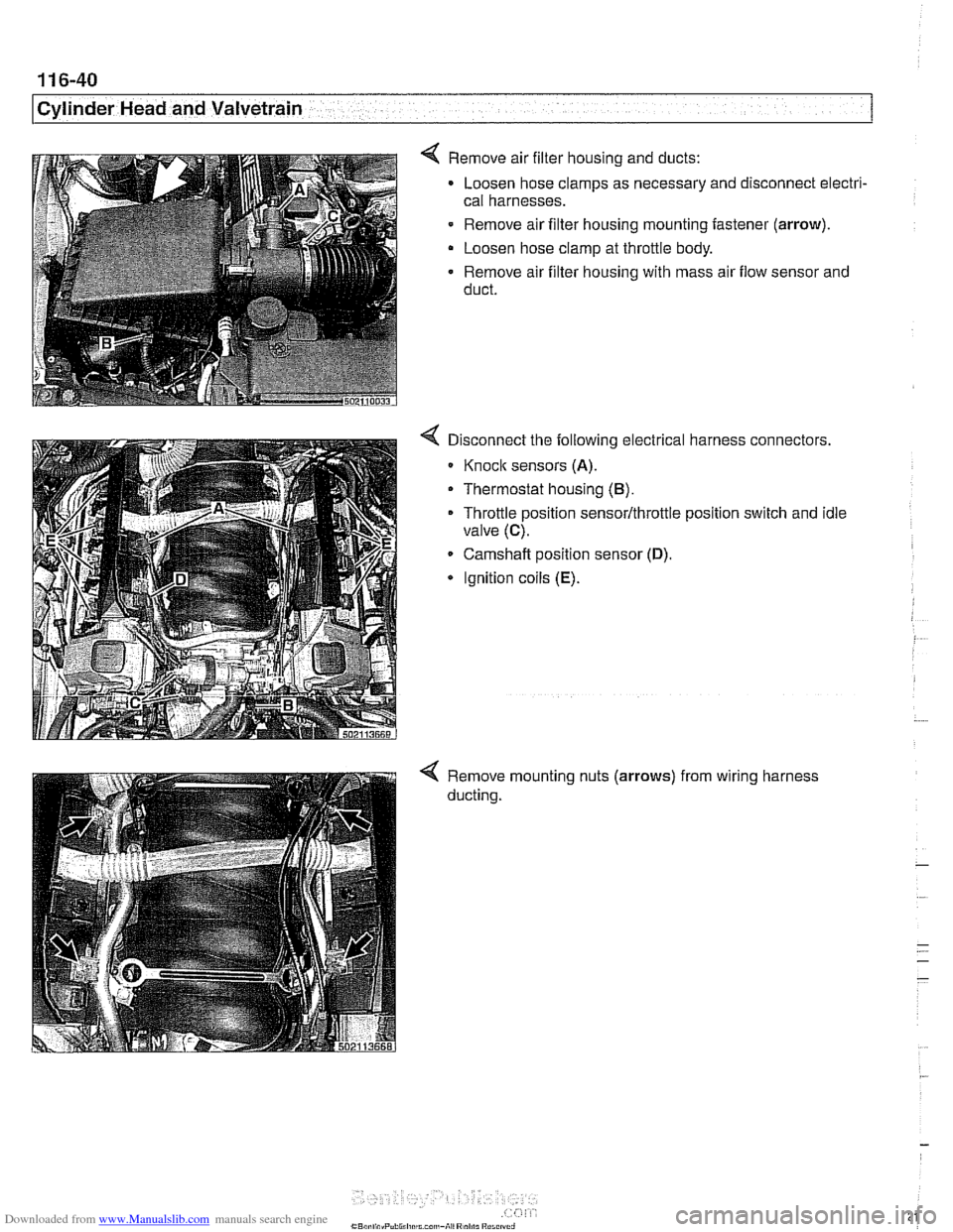
4 Remove air filter housing and ducts:
Loosen hose clamps as necessary and disconnect electri-
cal harnesses.
- Remove air filter housing mounting fastener (arrow).
Loosen hose clamp at throttle body.
Remove air filter housing with mass air flow sensor and
duct.
Disconnect the following electrical harness connectors.
Knoclc sensors (A).
Thermostat housing (B).
Throttle position sensor/throttle position switch and idle
valve
(C).
Camshaft position sensor (D).
* Ignition coils (E).
Remove mounting nuts (arrows)
ducting. from
wiring harness
Page 217 of 1002
Downloaded from www.Manualslib.com manuals search engine
Cylinder Head and Valvetrain
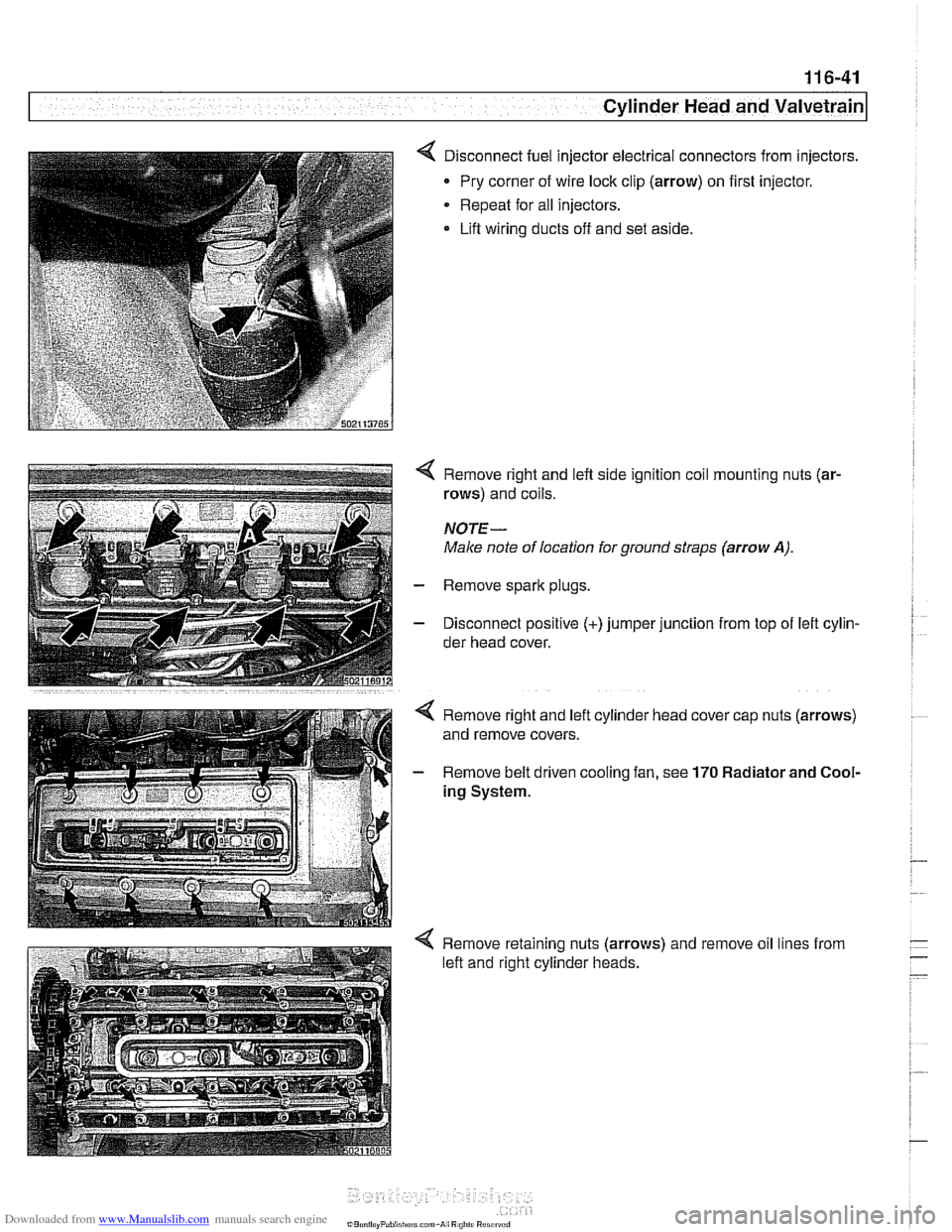
< Disconnect fuel injector electrical connectors from injectors.
Pry corner of wire lock clip (arrow) on first injector.
* Repeat for all injectors.
Lift wiring ducts off and set aside.
4 Remove right and left side ignition coil mounting nuts (ar-
rows) and coils.
NOTE-
Male note of location for ground straps (arrow A).
- Remove spark plugs.
- Disconnect positive (+)jumper junction from top of lefl cylin-
der head cover.
4 Remove retaining nuts (arrows) and remove oil lines from
left and right cylinder heads.
Page 219 of 1002
Downloaded from www.Manualslib.com manuals search engine
Cylinder Head and valvetrain1
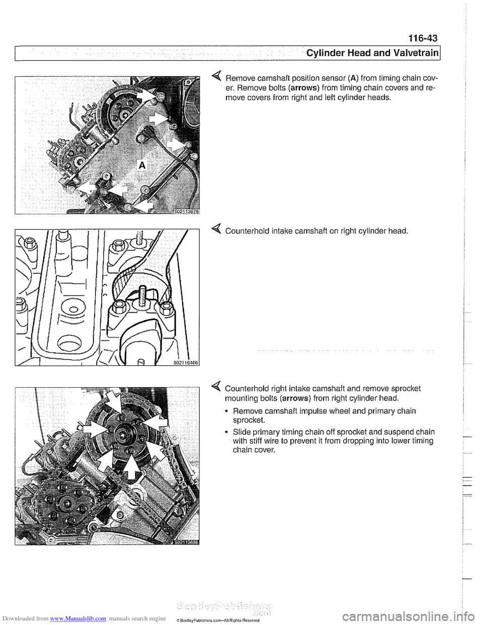
4 Remove camshaft position sensor (A) from timing chain cov-
er. Remove bolts
(arrows) from timing chain covers and re-
move covers from right and left cylinder heads.
4 Counterhold intalte carnshaft on right cylinder head
4 Counterhold right intalte camshaft and remove sprocltet
mounting bolts
(arrows) from right cylinder head.
Remove carnshaft impulse wheel and primary chain
sprocket.
- Slide primary timing chain off sprocltet and suspend chain
with stiff wire to prevent it from dropping into lower timing
chain cover.
Page 220 of 1002
Downloaded from www.Manualslib.com manuals search engine
..
ICylinder Head and Valvetrain -.I
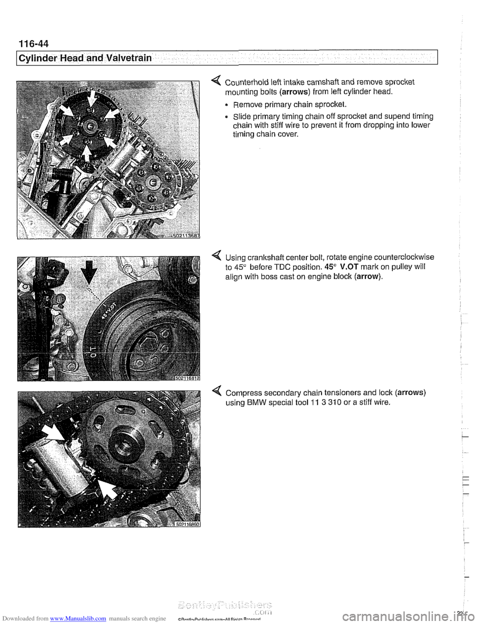
4 Counterhold left intake camshaft and remove sprocket
mounting bolts
(arrows) from left cylinder head.
Remove primary chain sprocket.
Slide primary timing chain off sprocket and
supend timing
chain with stiff wire to prevent it from dropping into lower
timing chain cover.
4 Using cranltshaft center bolt, rotate engine counterclockwise
to
45" before TDC position. 45" V.OT mark on pulley will
align with boss cast on engine block
(arrow).
4 Compress secondary chain tensioners and lock (arrows)
using BMW special tool 11 3 310 or a stiff wire.
Page 232 of 1002
Downloaded from www.Manualslib.com manuals search engine
1 16-56
Cylinder Head and Valvetrain
This section covers valve removal and reconditioning, includ-
ing valve guides, seats, springs, and valve stem oil seals.
Valves, leak test
To test the valves for leakage, the cylinder head must be dis-
assembled with camshafts and camshaft carriers removed.
With valve assemblies and spark plugs installed, place the
cylinder head on a workbench with the combustion chamber
facing upward. Fill each combustion chamber with a thin non-
flammable liquid. After fifteen minutes,
check the level of the
fluid. If the fluid level in any cylinder drops, that cylinder is not
sealing properly.
Valves, removing and installing
- Remove cylinder head as described in 113 Cylinder Head
Removal and Installation.
CAUTIOI\C
(M52 TU/M54 engines only) Do not let the hydraulic lifters
fall out as the camshaft carrier is removed. Special suction
cups are available from
BMW to hold the hydraulic lifters in
place during carrier removal.
* Hydraulic cam lifters should be stored m an uprfght po-
sition. If necessary, use a magnetic tool to
aidin remov-
al of the lifters.
- Remove valves using a valve spring compressor.
CAUTIOI\C
Label each valve assembly as it is removed so it can be in-
stalled in its original position.
-
- Remove and discard valve stem oil seals from valve guides.
See Valve stem oil seals later in this section.
- Valve installation is reverse of removal. Remove carbon de- - -
posits from the valves using a wire brush or wire wheel. -
-
Valve specifications are listed in Table c. Valve specifica-
tions.
Page 288 of 1002
Downloaded from www.Manualslib.com manuals search engine
11 7-52
Camshaft Timing Chain
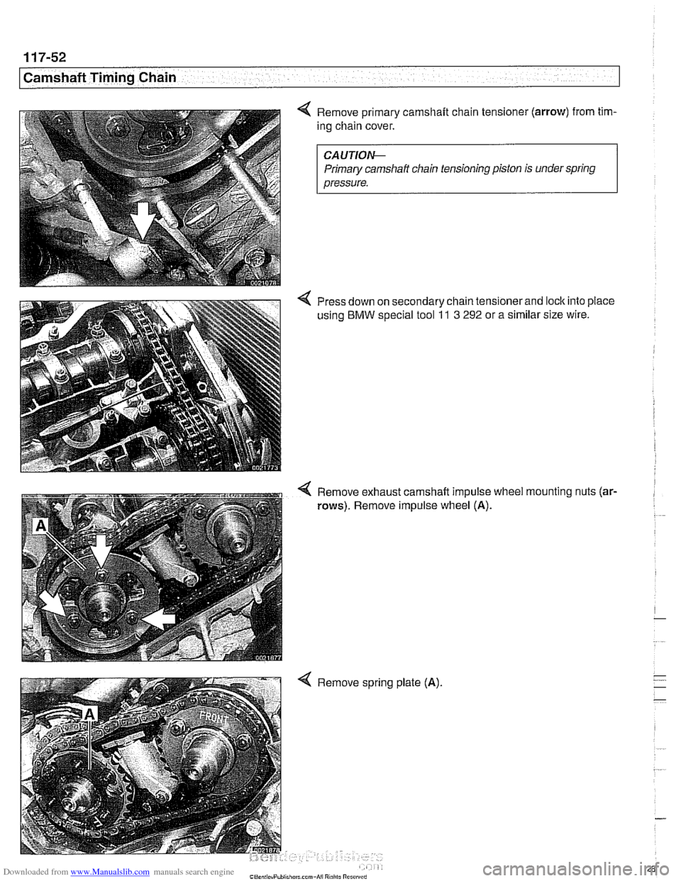
Remove primary camshaft chain tensioner (arrow) from tim-
ing chain cover.
CAUTIOIG
Primary camshaft chain tensioning piston is under spring
pressure.
Press down on secondary chain tensionerand lock into place
using
BMW special tool 11 3 292 or a similar size wire.
Remove exhaust camshaft impulse wheel
rows). Remove impulse wheel (A).
4 Remove spring plate (A). mounting
nuts
(ar-
Page 304 of 1002
Downloaded from www.Manualslib.com manuals search engine
1 17-68
Camshaft Timing Chain
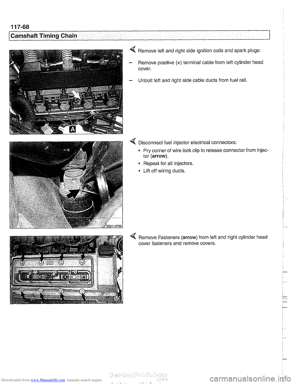
4 Remove left and right side ignition coils and spark plugs:
- Remove positive (+) terminal cable from left cylinder head
cover.
- Unbolt lefl and right side cable ducts from fuel rail,
4 Disconnect fuel injector electrical connectors:
Pry corner of wire lock clip to release connector from injec-
tor
(arrow).
Repeat for all injectors.
Lift off wiring ducts.
4 Remove Fasteners (arrow) from lefl and right cylinder head
cover fasteners and remove covers.
Page 309 of 1002
Downloaded from www.Manualslib.com manuals search engine
1 Camshaft Timing Chain
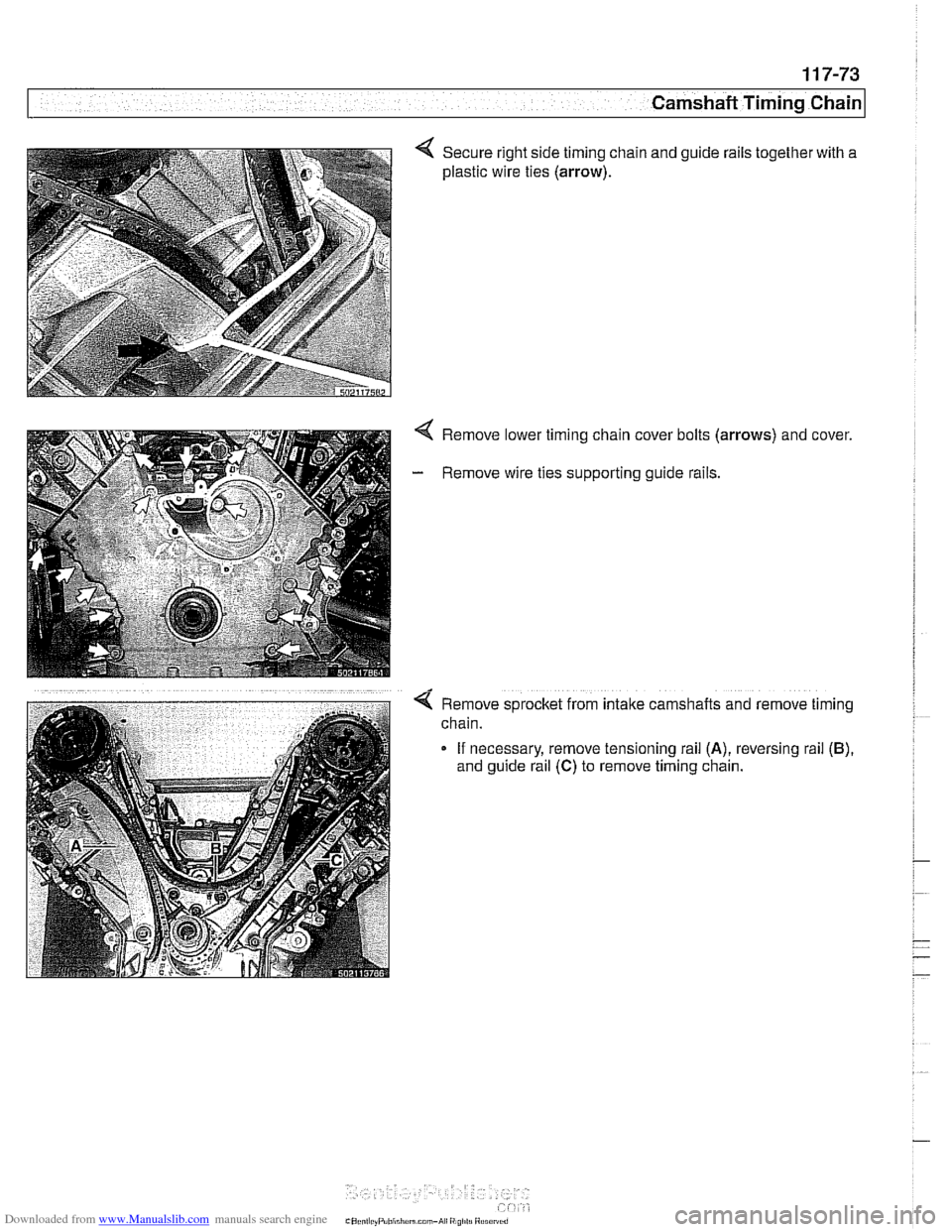
4 Secure right side timing chain and guide rails together with a
plastic wire ties
(arrow).
4 Remove lower timing chain cover bolts (arrows) and cover.
- Remove wire ties supporting guide rails.
-
Q Remove sprocket from intake camshafts and remove timing
chain.
If necessary, remove tensioning rail
(A), reversing rail (B),
and guide rail (C) to remove timing chain.