Wir BMW 540i 1997 E39 Repair Manual
[x] Cancel search | Manufacturer: BMW, Model Year: 1997, Model line: 540i, Model: BMW 540i 1997 E39Pages: 1002
Page 311 of 1002
Downloaded from www.Manualslib.com manuals search engine
Camshaft Timing Chain1
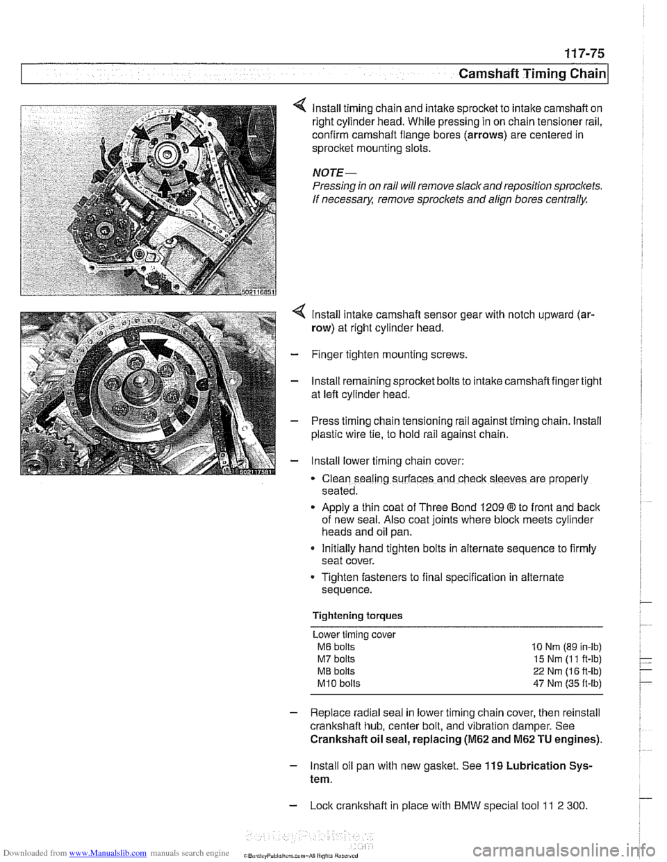
lnstall timing chain and intake sprocket to intake camshaft on
right cylinder head. While pressing in on chain tensioner rail,
confirm camshaft flange bores (arrows) are centered in
sprocket mounting slots.
NOTE-
Pressing in on rail will remove slack and reposition sprockets.
If
necessarx remove sproclets and align bores centrally.
lnstall intake camshaft sensor gear with notch upward (ar-
row) at right cylinder head.
- Finger tighten mounting screws.
- lnstall remaining sprocket bolts to intake camshaft finger tight
at left cylinder head.
- Press timing chain tensioning rail against timing chain. lnstall
plastic wire
tie, to hold rail against chain.
- lnstall lower timing chain cover:
Clean sealing surfaces and check sleeves are properly
seated.
Apply a thin coat of Three Bond 1209
8 to front and back
of new seal. Also coat joints where block meets cylinder
heads and oil pan.
Initially hand tighten bolts in alternate sequence to firmly
seat cover.
Tighten fasteners to final specification in alternate
sequence.
Tightening torques Lower timing cover
M6 bolts 10 Nrn (89 in-lb)
M7 bolts 15 Nm (1 1 ft-lb)
ME bolts 22 Nm (1 6 ft-lb)
M10 bolts 47 Nm (35 ft-lb)
- Replace radial seal in lower timing chain cover, then reinstall
crankshaft hub, center bolt, and vibration damper. See
Crankshaft oil seal, replacing
(M62 and M62 TU engines).
- lnstall oil pan with new gasket. See 119 Lubrication Sys-
tem.
- Lock crankshaft in place with BMW special tool 11 2 300
Page 314 of 1002
Downloaded from www.Manualslib.com manuals search engine
[camshaft Timina Chain
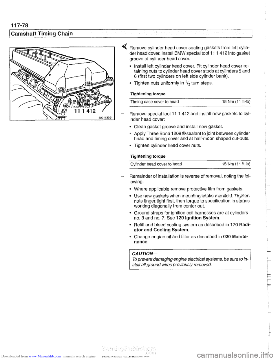
< Remove cylinder head cover sealing gaskets from lefl cylin-
der head cover. Install
BMW special tool 11 1 412 into gasket
groove of cylinder head cover.
Install lefl cylinder head cover. Fit cylinder head cover re-
taining nuts to cylinder head cover studs at cylinders
5 and
6 (first two cylinders on left side cylinder bank).
Tighten nuts uniformly in
'I2 turn steps
Tightening torque
Timing case cover to head
15 Nm (1 1 ft-lb)
- Remove special tool 11 1 41 2 and install new gaskets to cyl-
inder head cover:
Clean gasket groove and install new gasket.
Apply Three Bond
12098sealant tojoint between cylinder
head and timing cover and at half-moon shaped cut-outs.
Tighten cylinder head cover nuts.
Tightening torque Cylinder head cover to head
I5 Nm (1 1 ft-lb)
- Remainder of installation is reverse of removal, noting the fol-
lowing:
Where applicable remove protective film from gaskets.
Use new gaskets when mounting intake manifold. Tighten
nuts finger tight first, then torque to specification in stages
worlting diagonally from center out.
Ground straps for ignition coil harnesses are at cylinders
no.
3 and no. 7. See 120 Ignition System.
Refill and bleed cooling system as described in
170 Radi-
ator and Cooling System.
Change engine oil and filter as described in
020 Mainte-
nance.
CAUTIOI\C
To prevent damaging engine electrical systems, be sure to in-
stall ail ground wires previously removed.
Page 316 of 1002
Downloaded from www.Manualslib.com manuals search engine
Camshaft Timing Chain LL. .- - - - I
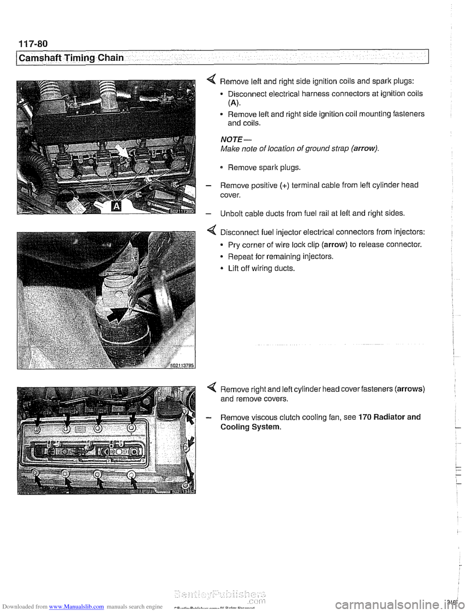
4 Remove left and right side ignition coils and spark plugs:
- Disconnect electrical harness connectors at ignition coils
(A).
Remove left and right side ignition coil mounting fasteners
and coils.
NOTE-
Make note of location of ground strap (arrow).
Remove sparlc plugs.
- Remove positive (+) terminal cable from left cylinder head
cover.
- Unbolt cable ducts from fuel rail at left and right sides.
Disconnect fuel injector electrical connectors from injectors:
Pry corner of wire
loclc clip (arrow) to release connector.
Repeat for remaining injectors.
* Lift off wiring ducts.
Page 325 of 1002
Downloaded from www.Manualslib.com manuals search engine
. .- -
L
- --
- - -. - -- Lubrication ~~stern
- Remove pressure gauge and reinstall pressure switch with
new sealing washer.
Tightening torque
Oil pressure switch to oil filter housing 27 Nm (20 ft-lb)
If testing shows low oil pressure, one or more of the following
conditions may be indicated:
Worn or faulty oil pump or faulty pump pressure relief valve
Worn or damaged engine bearings
Severe engine wear
Any of these conditions indicate the need for major repairs.
Oil pressure warning system, testing
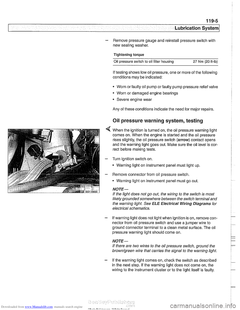
4 When the ignition is turned on, the oil pressure warning light
comes on. When the engine is started and the oil pressure
rises slightly, the oil pressure switch (arrow) contact opens
and the warning light goes out. Make sure the oil level is cor-
rect before making tests.
- Turn ignition switch on.
- Warning light on instrument panel must light up
- Remove connector from oil pressure switch.
Warning light on instrument panel must go out.
NOTE-
If the light does not go out, the wiring to the switch is most
likely grounded somewhere between the switch terminaland
the warning light See
ELE Electrical Wiring Diagrams for
electrical schematics.
- If warning light does not light when ignition is on, remove con-
nector from oil pressure switch and use a jumper wire to
ground connector terminal to a clean metal surface. The oil
pressure warning light should come on.
NOTE-
If there are two wires to the oil pressure switch, ground the
brown/green wire that carries the signal to the warning light.
- If the warning light comes on, check the switch as described
in the next step. If the warning light does not come on, the
wiring to the instrument cluster or to the light itself is faulty.
Page 330 of 1002
Downloaded from www.Manualslib.com manuals search engine
11 9-1 0
Lubrication System
Oil pan, removing and installing
(6-cylinder)
The engine oil pan removal procedure requires that the en-
gine be supported from the top and the front suspension
sub-
frame be lowered.
- Raise car and place securely on jack stands.
Make sure the car is stable and well supported at all times.
Use a professional automotive
lift orjackstands designed for
- Remove splash shield from under engine.
- Drain engine oil as described in 020 Maintenance.
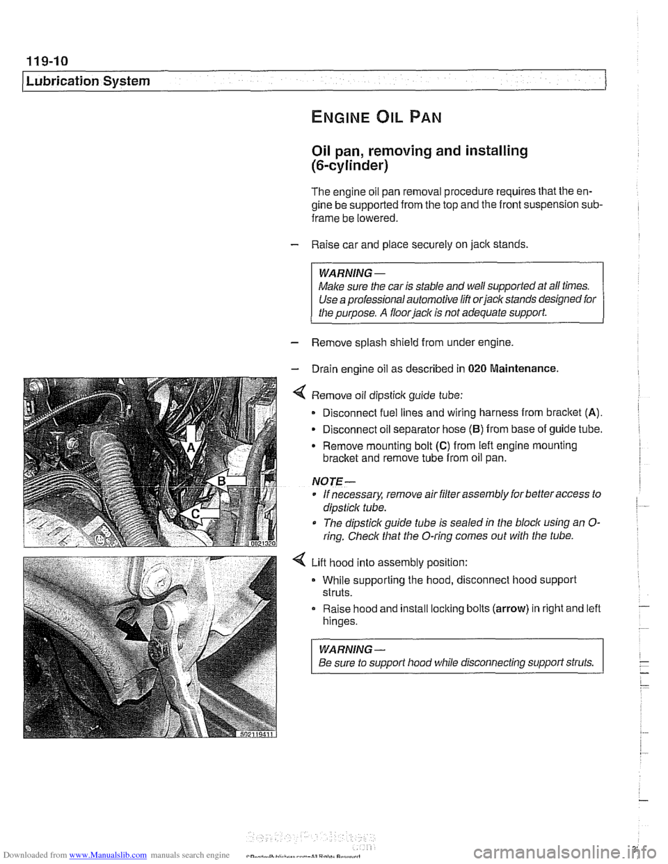
4 Remove oil dipsticlc guide tube:
Disconnect fuel lines and wiring harness from
bracket (A).
- Disconnect oil separator hose (B) from base of guide tube.
Remove mounting bolt
(C) from left engine mounting
bracket and remove tube from oil pan.
NOTE-
* If necessary, remove air filter assembly for better access to
dipsticlc tube.
The dipstick guide tube is sealed in the block using an
O-
ring. Check that the O-ring comes out with the tube.
4 Lift hood into assembly position:
While supporting the hood, disconnect hood support
struts.
Raise hood and install
loclting bolts (arrow) in right and left
hinges.
WARNING-
Be sure to support hood while disconnecting support struts.
Page 331 of 1002
Downloaded from www.Manualslib.com manuals search engine
Lubrication system/
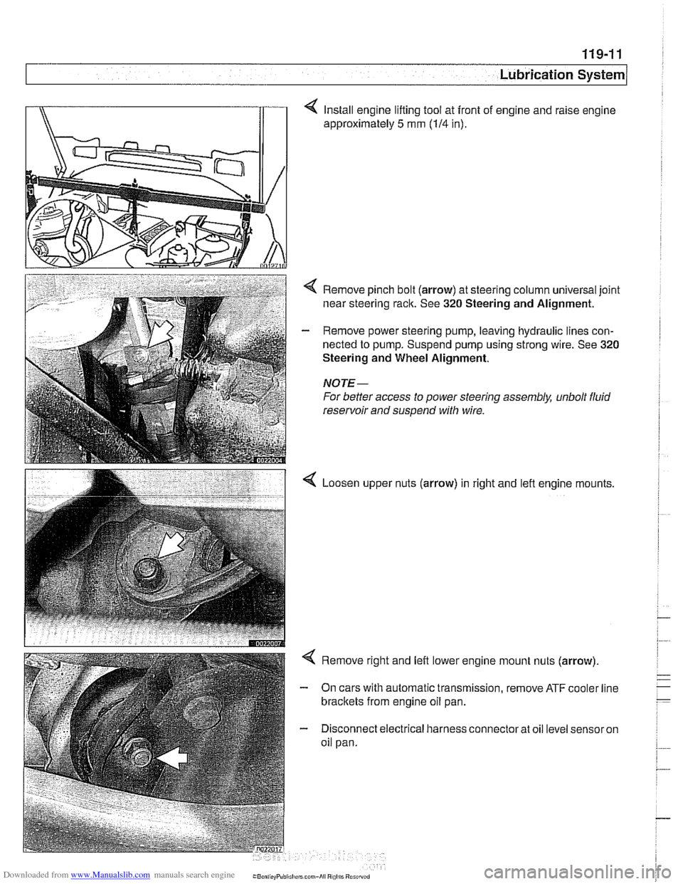
4 Install engine lifting tool at front of engine and raise engine
approximately
5 mm (114 in).
< Remove pinch bolt (arrow) at steering column universal joint
near steering rack. See
320 Steering and Alignment.
- Remove power steering pump, leaving hydraulic lines con-
nected to pump. Suspend pump using strong wire. See
320
Steering and Wheel Alignment.
NOTE-
For better access to power steering assembly, unbolt fluid
reservoir and suspend with wire.
Loosen upper nuts (arrow) in right and lefl engine mounts,
< Remove right and left lower engine mount nuts (arrow)
- On cars with automatic transmission, remove ATF cooler line
brackets from engine oil pan.
- Disconnect electrical harness connector at oil level sensor on
oil pan.
Page 337 of 1002
Downloaded from www.Manualslib.com manuals search engine
1 19-1 7
Lubrication System
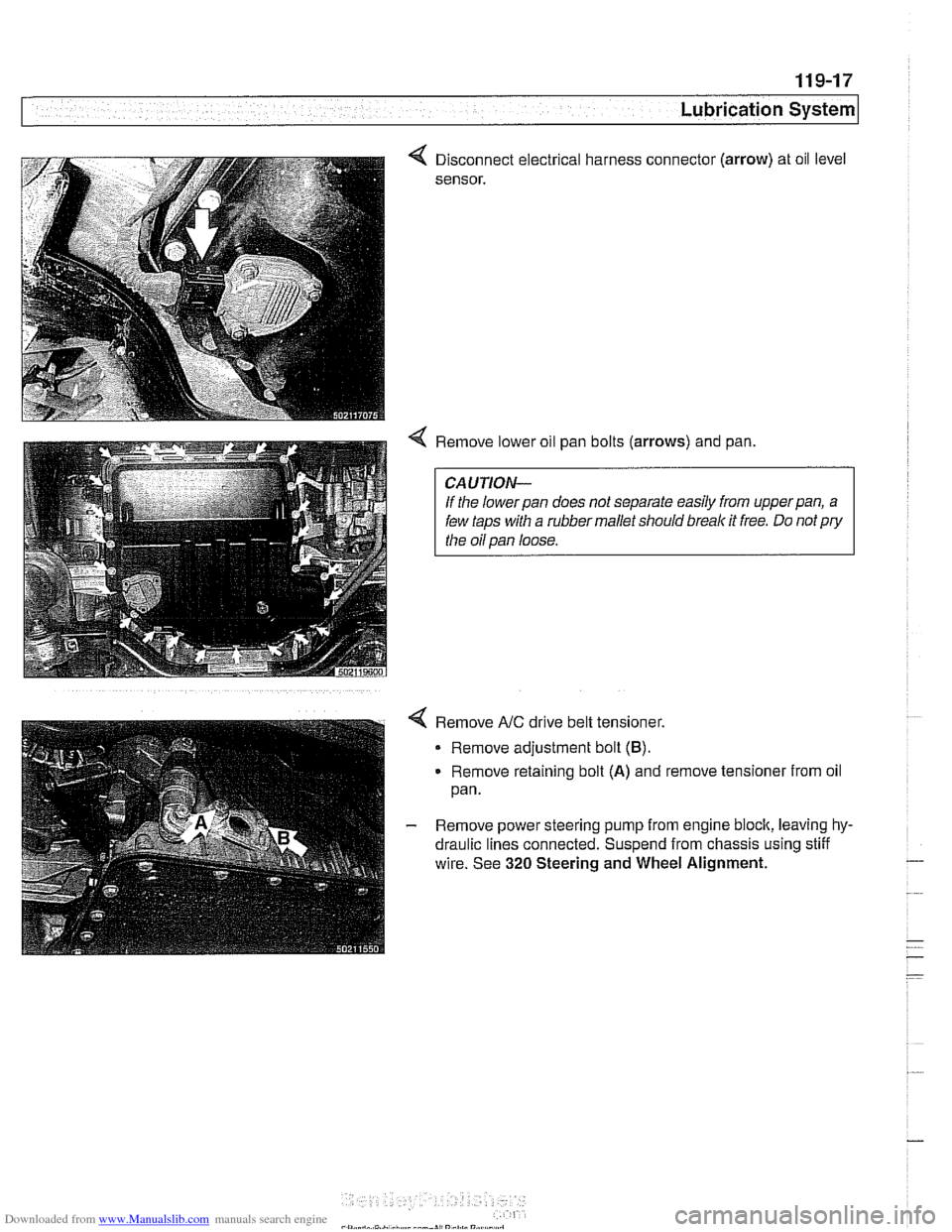
Disconnect electrical harness connect01
sensor.
. (arrow)
4 Remove lower oil pan bolts (arrows) and pan, oil
level
CAUTION-
If the lowerpan does not separate easily from upperpan, a
few taps with a rubber mallet should break it free. Do not pry
the oil pan loose.
Remove
NC drive belt tensioner.
Remove adjustment bolt
(B).
Remove retaining bolt (A) and remove tensioner from oil
pan.
- Remove power steering pump from engine block, leaving hy-
draulic lines connected. Suspend from chassis using stiff
wire. See
320 Steering and Wheel Alignment.
Page 350 of 1002
Downloaded from www.Manualslib.com manuals search engine
Ignition System
This repair group covers component troubleshooting and re-
placement information for the ignition system.
When diagnosing engine management problems, including
on-board diagnostics (OBD
11) fault code analysis, also refer
to these repair groups:
* 130 Fuel Injection
* ELE Electrical Wiring Diagrams
OED On-Board Diagnostics
Special tools
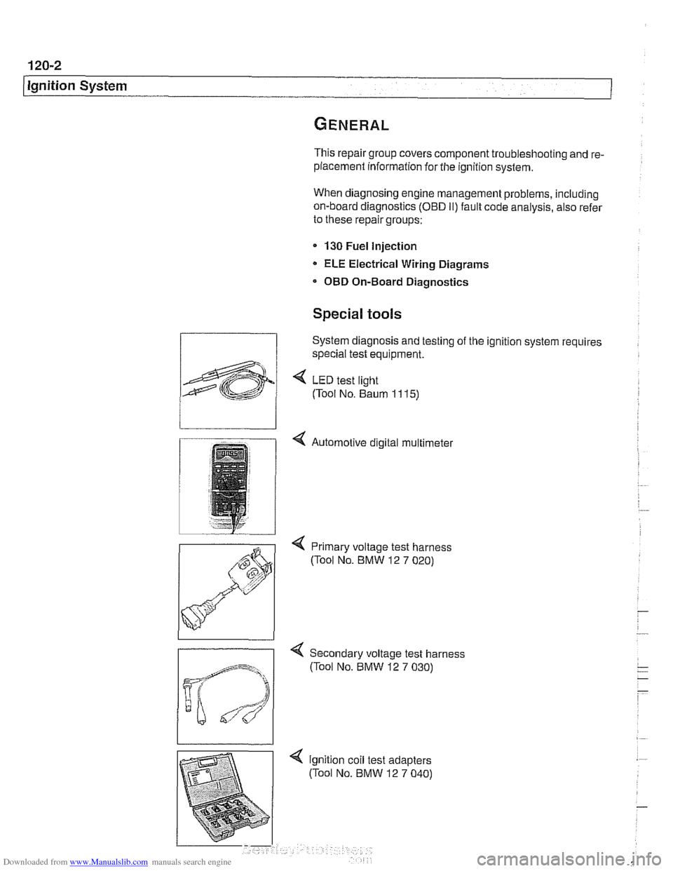
System diagnosis and testing of the ignition system requires
special test equipment.
4 LED test light
(Tool No. Baum
1 1 15)
4 Automotive digital multimeter
4 Primary voltage test harness
(Tool No. BMW 12
7 020)
-
4 Secondary voltage test harness
(Tool No. BMW 12
7 030)
Page 351 of 1002
Downloaded from www.Manualslib.com manuals search engine
120-3
Ignition System
Warnings and cautions
The ignition system produces dangerous high voltage. In ad-
dition the sensitive electronic components can be damaged
if
proper precautions are not adhered to.
WARNING-
* Do not touch or disconnect any cables from the coils while
the engine is running or being
cranked by the starter.
The ignition system produces high voltages that can be
fatal. Avoid contact with exposed terminals. Use ex-
treme caution when working on a car with the ignition
switched on or the engine running.
- Connect and disconnect tlie DME system wiring and
test equipment leads only when the ignition is
OFF:
Before operating the starter without starting the engine
(for example when
making a compression test) always
disable the ignition.
CA
U TIOW-
Do not attempt to disable the ignition by removing the coils
from the spark plugs.
Connect or disconnect ignition system wires, multiple
wire connectors, and ignition test equipment leads only
while the ignition is
off Switch multimeter functions or
measurement ranges only with the test probes discon-
nected.
* Do not disconnect the battery while the engine is run-
ning.
A high impedance digital multimeter should be used for
all voltage and resistance tests. An LED test light
should be used in place of an incandescent-type test
lamp.
In general, make test connections only as specified by
BMW as described in this manual, or as described by
the instrument manufacturer.
Engine management
BMW €39 engines use an advanced engine management
system known as Digital Motor Electronics (DME). DME in-
corporates on-board diagnostics, fuel injection, ignition and
other engine control functions. DME variants are listed in
Table a. Engine management systems.
Second generation On-Board Diagnostics
(OED II) is incor-
porated into the engine management systems used on the
cars covered by this manual. Use a BMW-specific electronic
scan tool, or a "Generic"
OED II scan tool to access Diagnos-
tic Trouble Codes (DTCs). DTCs can help pinpoint ignition
ine management problems.
Page 353 of 1002
Downloaded from www.Manualslib.com manuals search engine
Lnition switch
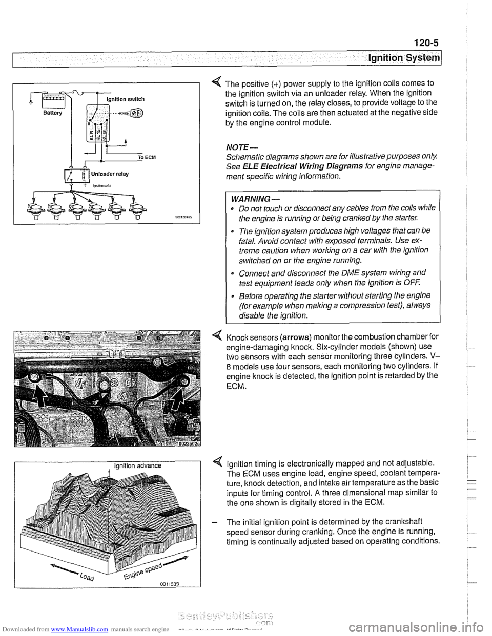
4 The positive (+) power supply to the ignition coils comes to
the ignition switch via an unloader relay. When the ignition
switch is turned on, the relay closes, to provide voltage to the
ignition coils. The coils are then actuated at the negative side
by the engine control module.
NOTE-
Schematic diagrams shown are for illustrative purposes only.
See ELE Electrical Wiring Diagrams for engine manage-
ment specific wiring information.
WARNING- Do not touch or disconnect any cables from the coils while
the engine is running or being cranked by the starter:
The ignition system produces high voltages that can be
fatal. Avoid contact with exposed terminals. Use ex-
treme caution when
working on a car with the ignition
switched on or the engine running.
* Connect and disconnect the DME system wiring and
test equipment leads only when the ignition is
OFF
Before operating the starter without starting the engine
(for example when
making a compression test), always
disable the ignition.
4 Knock sensors (arrows) monitor the combustion chamber for
engine-damaging knock. Six-cylinder models (shown) use
two sensors with each sensor monitoring three cylinders.
V-
8 models use four sensors, each monitoring two cylinders. If
engine
knock is detected, the ignition point is retarded by the
ECM.
I Ignition advance Ignition timing is electronically mapped and not adjustable.
The ECM uses engine load, engine speed, coolant tempera-
ture, knock detection, and intake air temperature as the basic
inputs for timing control.
A three dimensional map similar to
the one shown is digitally stored in the ECM.
- The initial ignition point is determined by the crankshaft
speed sensor during cranking. Once the engine is running.
timing is continually adjusted based on operating conditions.