engine removal BMW 540i 1997 E39 Workshop Manual
[x] Cancel search | Manufacturer: BMW, Model Year: 1997, Model line: 540i, Model: BMW 540i 1997 E39Pages: 1002
Page 545 of 1002
Downloaded from www.Manualslib.com manuals search engine
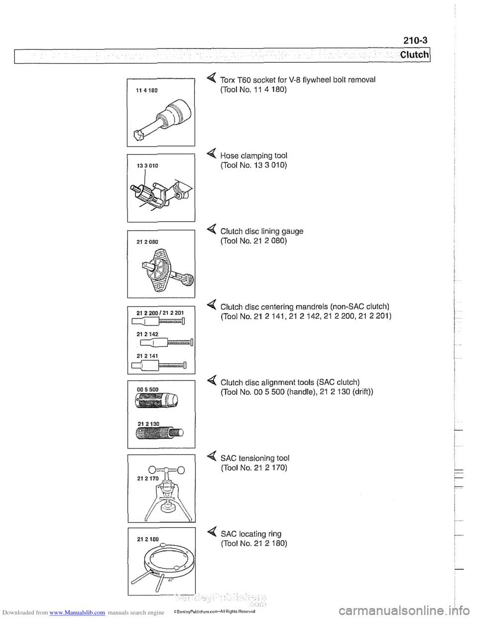
4 Tom T60 socket for V-8 flywheel bolt removal
(Tool No. 1 1 4 180)
4 Hose clamping tool
(Tool No. 13 3
01 0)
4 Clutch disc lining gauge
(Tool No. 21 2 080)
4 Clutch disc centering mandrels (non-SAC clutch)
(Tool No. 21 2
141,21 2 142,21 2 200,21 2 201)
4 Clutch disc alignment tools (SAC clutch)
(Tool No. 00 5 500 (handle). 21 2 130 (drift))
4 SAC tensioning tool
(Tool No. 21 2 170)
4 SAC locating ring
(Tool No. 21 2 180)
Page 550 of 1002
Downloaded from www.Manualslib.com manuals search engine
21 0-8
Clutch
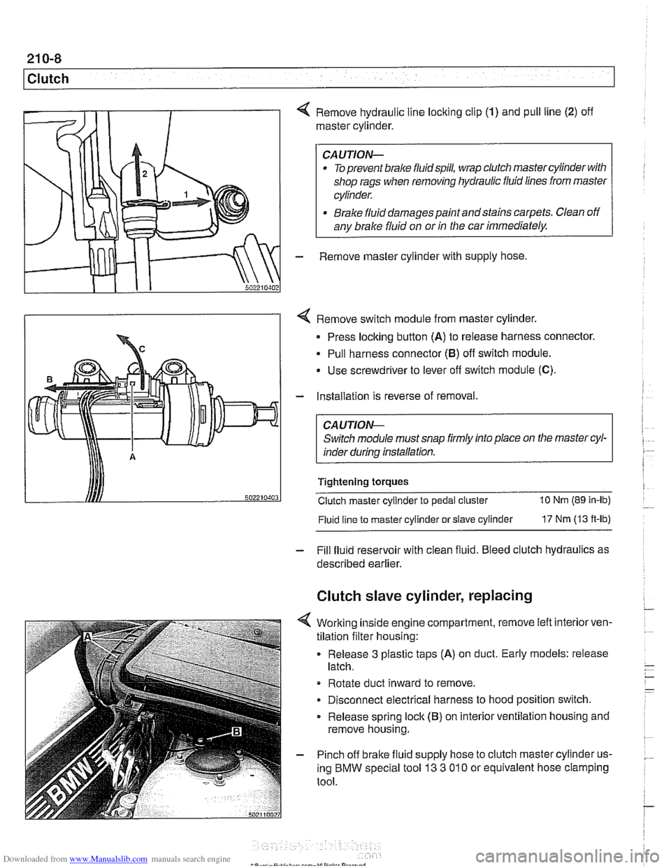
4 Remove hydraulic line locking clip (1) and pull line (2) off
master cylinder.
CAUTION-
. To prevent brake fluidspill, wrap clutch master cylinder with
shop rags when removing hydraulic fluid lines from master
cylinder.
* Brake fluid damages paint andstains carpets. Clean off
any brake fluid on or
in the car immediately.
- Remove master cylinder with supply hose
4 Remove switch module from master cylinder.
Press locking button
(A) to release harness connector.
Pull harness connector
(8) off switch module.
Use screwdriver to lever
off switch module (C).
- Installation is reverse of removal.
CA UTlON-
Switch module must snap firmly into place on the master cyl-
inder during installation.
Tightening torques
Clutch master cylinder to pedal cluster
10 Nm (89 in-lb)
Fluid line
to master cylinder or slave cylinder 17 Nm (13 ft-lb)
- Fill fluid reservoir with clean fluid. Bleed clutch hydraulics as
described earlier.
Clutch slave cylinder, replacing
4 Working inside engine compartment, remove left interiorven-
tilation filter housing:
Release
3 plastic taps (A) on duct. Early models: release
latch.
Rotate duct inward to remove.
Disconnect electrical harness to hood position switch.
Release spring lock (B) on interior ventilation housing and
remove housing.
- Pinch off brake fluid supply hose to clutch master cylinder us-
ing BMW special tool
13 3 01 0 or equivalent hose clamping
tool.
Page 551 of 1002
Downloaded from www.Manualslib.com manuals search engine
- Raise and safely support vehicle
WARNING-
Make sure the car is stable and well supporied at all times.
Use a professional automotive /iff orjack stands designed for
the
ournose. A floor jack is not adeouate suooort.
- If necessary, remove transmission splash shield.
- Disconnect fluid line from slave cylinder on lefl side of trans-
mission. Place pan under hose to catch dripping fluid.
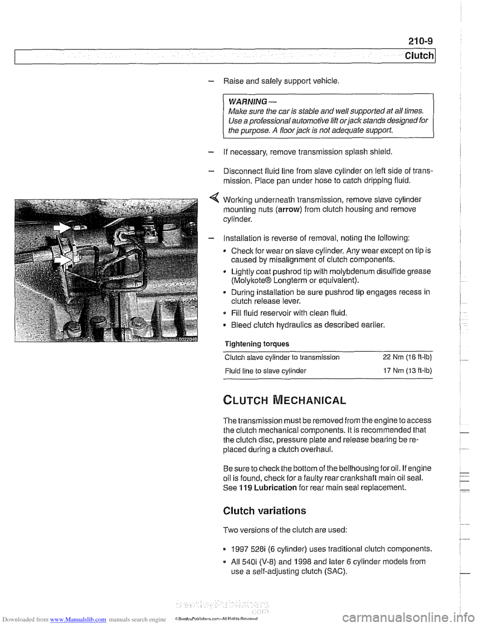
4 Working underneath transmission, remove slave cylinder
mounting nuts (arrow) from clutch housing and remove
cylinder.
- Installation is reverse of removal, noting the following:
Check for wear on slave cylinder. Any wear except on tip is
caused by misalignment of clutch components.
Lightly coat
pushrod tip with molybdenum disulfide grease
(MolyltoteIB Longterm or equivalent).
. During installation be sure pushrod tip engages recess in
clutch release lever.
Fill fluid reservoir with clean fluid.
. Bleed clutch hydraulics as described earlier.
Tightening
toraues - -.
Clutch slave cylinder to transmission 22 Nm (16 R-lb)
Fluid line to slave cylinder 17 Nm (13 ft-lb)
The transmission must be removed from the engine to access
the clutch mechanical components. It is recommended that
the clutch disc, pressure plate and release bearing be re-
placed during a clutch overhaul.
Besure tocheck the bottom of the bellhousing foroil. If engine
oil is found, check for a faulty rear crankshaft main oil seal.
See
119 Lubrication for rear main seal replacement.
Clutch variations
Two versions of the clutch are used:
1997 528i (6 cylinder) uses traditional clutch components.
All
540i (V-8) and 1998 and later 6 cylinder models from
use a self-adjusting clutch (SAC).
Page 565 of 1002
Downloaded from www.Manualslib.com manuals search engine
230 Manual Transmission
General ........................... .23 0.2 Output shaft
seal. replacing (5-speed
.... Special tools ........................ .23 0.2 transmission) (transmission installed) 230-10
Manual transmission aoolications ....... .23 0.5 Output shaft seal. replacing (6-speed . . .... transmission) (transmission installed) 230-12 ........ Transmission Fluid Service .23 0.6 put shaft seal. replacing
Transmission fluid level. checking ....... .23 0.6 (transmission ............... 230-15
........... Transmission fluid, replacing .23 0.6
Transmission Removal ................... ..... Transmission External Service .23 0-7 and installation 230-1
Back-up light switch, replacing .......... .23 0-' Transmission, removing and installing 230-16 ...
Selector shaft seal. reolacina .
(transmission installed) ................ .23 0.8
Page 566 of 1002
Downloaded from www.Manualslib.com manuals search engine
230-2
I Manual Transmission
This repair group covers external transmission service, including removal and installation of the transmission unit.
Internal transmission repair is not covered. Special tools and
procedures are required to disassemble and
service the
internal geartrain.
Special tools
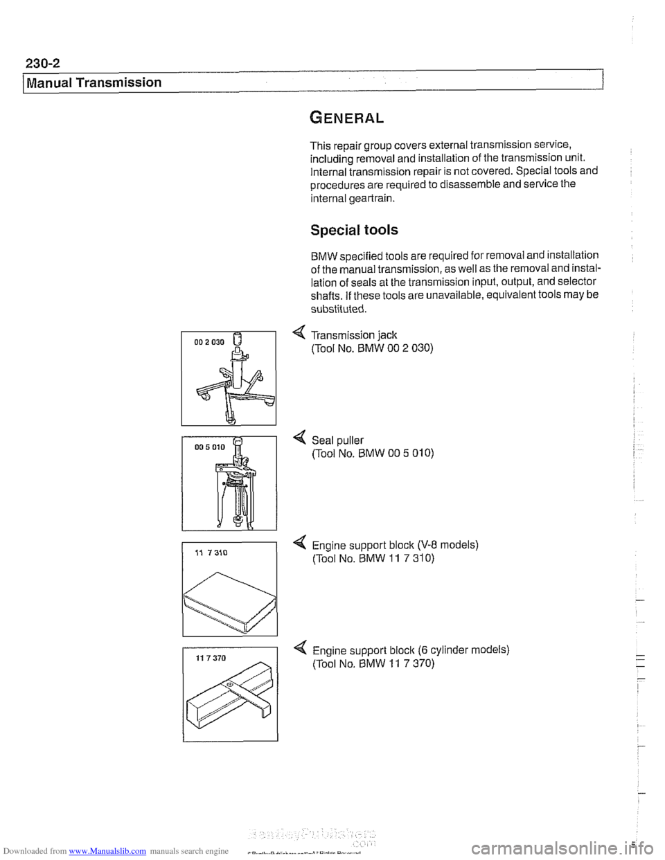
BMW specified tools are required for removal and installation
of the manual transmission, as well as the removal and instal-
lation of seals at the transmission input, output, and selector
shafts. If these tools are unavailable, equivalent tools may be
substituted.
4 Transmission jack
(Tool No, BMW 00 2 030)
4 Seal puller
(Tool No. BMW 00
5 01 0)
4 Engine support block (V-8 models)
(Tool No. BMW
11 7 31 0)
4 Engine support bloclc (6 cylinder models)
(Tool No.
BMW 11 7 370)
Page 573 of 1002
Downloaded from www.Manualslib.com manuals search engine
230-9
Manual ~ransmissionl
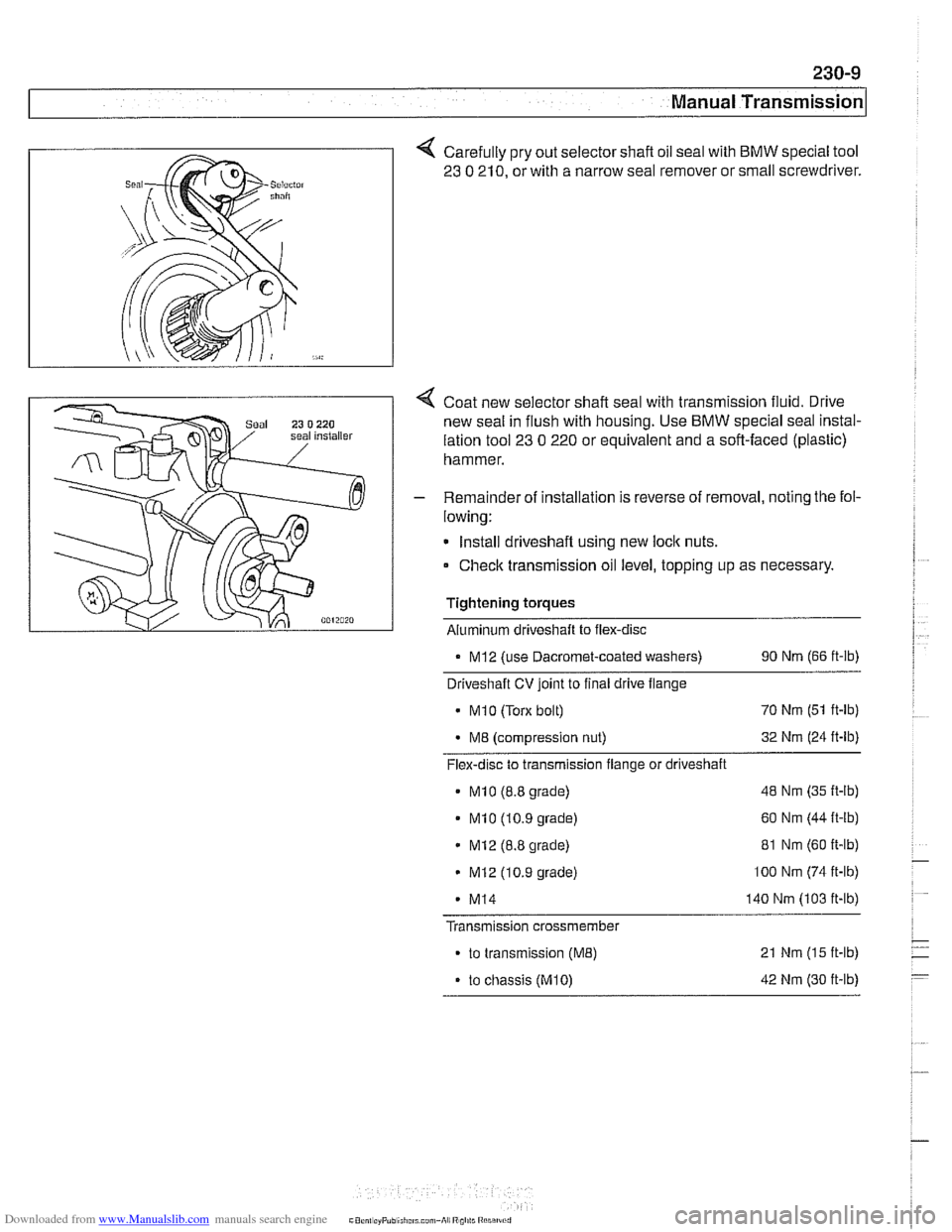
Carefully pry out selector shaft oil seal with BMW special tool
23
0 210, or with a narrow seal remover or small screwdriver.
Coat new selector shaft seal with transmission fluid. Drive
new seal in flush with housing. Use
BMW special seal instal-
lation tool
23 0 220 or equivalent and a soft-faced (plastic)
hammer.
- Remainder of installation is reverse of removal, noting the fol-
lowing:
Install driveshaft using new
loclc nuts.
Check transmission oil level, topping up as necessary.
Tightening torques Aluminum driveshaft to flex-disc
. MI2 (use Dacromet-coated washers) 90 Nm (66 ft-lb)
Driveshaft CV joint to final drive flange
MI 0 (Torx bolt) 70
Nm (51 ft-lb)
M8 (compression nut) 32
Nm (24 ft-lb)
Flex-disc to transmission flange or driveshaft
MI0 (8.8 grade) 48 Nm (35 ft-lb)
MI0 (10.9 grade) 60
Nm (44 it-lb)
MI2 (8.8 grade) 81
Nm (60 ft-lb)
MI2 (10.9 grade) lo0 Nm (74 ft-lb)
- MI4 140 Nm (103 ft-lb)
Transmission crossmember
to transmission (ME) 21 Nm (15 ft-lb)
. to chassis (M10) 42 Nm (30 ft-lb)
Page 575 of 1002
Downloaded from www.Manualslib.com manuals search engine
230-1 1
Manual ~ransmissionl
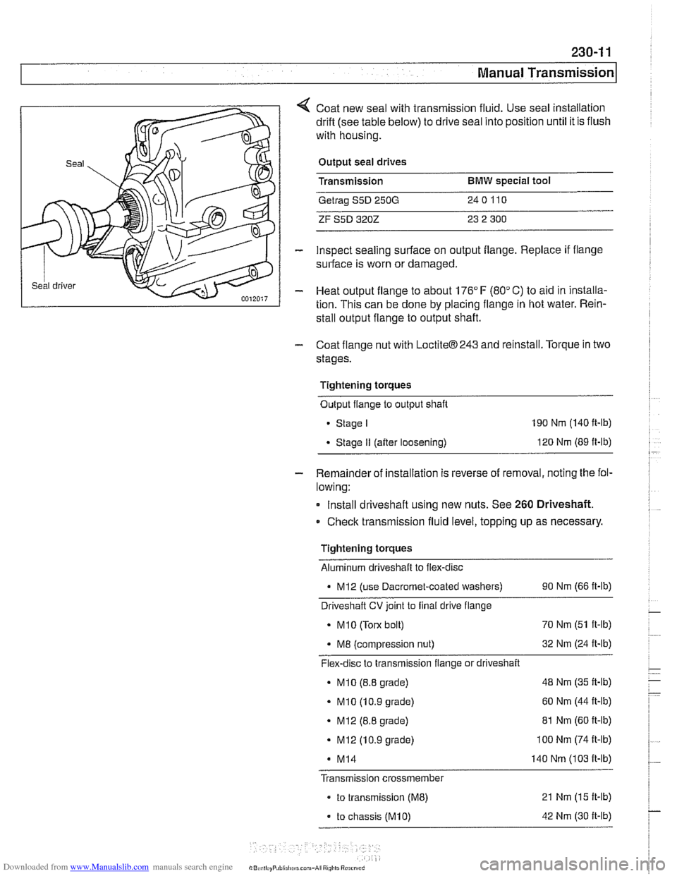
Coat new seal with transmission fluid. Use seal installation
drift (see table below) to drive seal into position until it is flush
with housing.
Output seal drives
Transmission
BMW special tool
Getrag S5D 250G 240110
ZF S5D 3202 23 2 300
inspect sealing surface on output flange. Replace if flange
surface is worn or damaged.
Heat output flange to about 176"
F (80" C) to aid in installa-
tion. This can be done by placing flange in hot water. Rein-
stall output flange to output shaft.
- Coat flange nut with LoctiteB243 and reinstall. Torque in two
stages.
Tightening torques Output flange to output shaft
Stage I 190 Nm (140 ft-lb)
Stage II (after loosening) 120
Nm (89 ft-lb)
- Remainder of installation is reverse of removal, noting the fol-
lowing:
Install driveshaft using new nuts. See
260 Driveshaft.
Check transmission fluid level, topping up as necessary
Tightening torques Aluminum driveshaft to flex-disc
- MI2 (use Dacromet-coated washers) 90 Nm (66 ft-lb)
Driveshaft
CV joint to final drive flange
. MI0 (Torx bolt) 70
Nm (51 ft-lb)
. M8 (compression nut) 32
Nm (24 ft-lb)
Flex-disc to transmission flange or driveshaft
- MI0 (8.8 grade) 48
Nm (35 ft-lb)
- MI0 (10.9 grade) 60
Nm (44 It-lb)
. MI2 (8.8 grade) 81 Nm (60 ft-lb)
. MI2 (10.9 grade) I00 Nm (74 It-lb)
M14 140 Nm (103 It-lb)
Transmission crossmember
- to transmission (ME) 21 Nm (15 It-lb)
- to chassis (M10) 42 Nm (30 It-lb)
Page 578 of 1002
Downloaded from www.Manualslib.com manuals search engine
230-14
I Manual Transmission
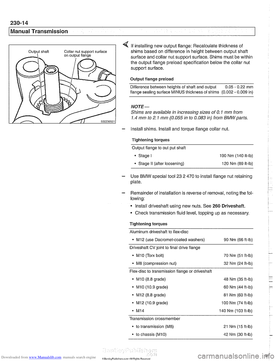
If installing new output flange: Recalculate thickness of
shims based on difference in height between output shaft
surface and collar nut support surface. Shims must be within
the output flange preload specification below the collar nut
support surface.
Output flange preload Difference between heights of shaft and output 0.05
- 0.22 mm
flange sealing
suriace MINUS thickness of shims (0.002 - 0.009 in)
NOTE-
Shims are available in increasing sizes of 0.1 mm from
1.4 mm to 2.1 mm (0.055 in to 0.083 in) from BMWparts.
- Install shims. Install and torque flange collar nut.
Tightening torques Output flange to out put shaft
. Stage I 190 Nm (140 ft-lb)
. Stage II (after loosening) 120 Nm (89 it-lb)
- Use BMW special tool 23 2 470 to install flange nut retaining
plate.
- Remainder of installation is reverse of removal, noting the fol-
lowing:
Install driveshaft using new nuts. See
260 Driveshaft.
Checlc transmission fluid level, topping up as necessary.
Tightening torques
Aluminum driveshaft to flex-disc
- MI2 (use Dacromet-coated washers) 90 Nm (66 ft-lb)
Driveshaft
CV joint to final drive flange
MI0 (Tom bolt)
70 Nm (51 ft-lb)
M8 (compression nut) 32 Nm (24 ft-lb)
Flex-disc to transmission flange or driveshaft
* MI0 (8.8 grade) 48 Nm (35 ft-lb)
- MI0 (10.9 grade) 60 Nm (44 ft-lb)
. MI2 (8.8 grade)
81 Nm (60 ft-lb)
MI2 (10.9 grade) 100 Nm (74 ft-lb)
- MI4 140 Nm (1 03 ft-lb)
Transmission
crossmembe~
to transmission (ME)
to chassis (M10)
21 Nm (15 ft-lb)
42 Nm (30 it-lb)
Page 579 of 1002
Downloaded from www.Manualslib.com manuals search engine
Manual Transmission
Input shaft seal, replacing
(transmission removed)
- Remove transmission from vehicle as described later in this
group.
- Remove clutch release bearing end release bearing lever
from inside bellhousing.
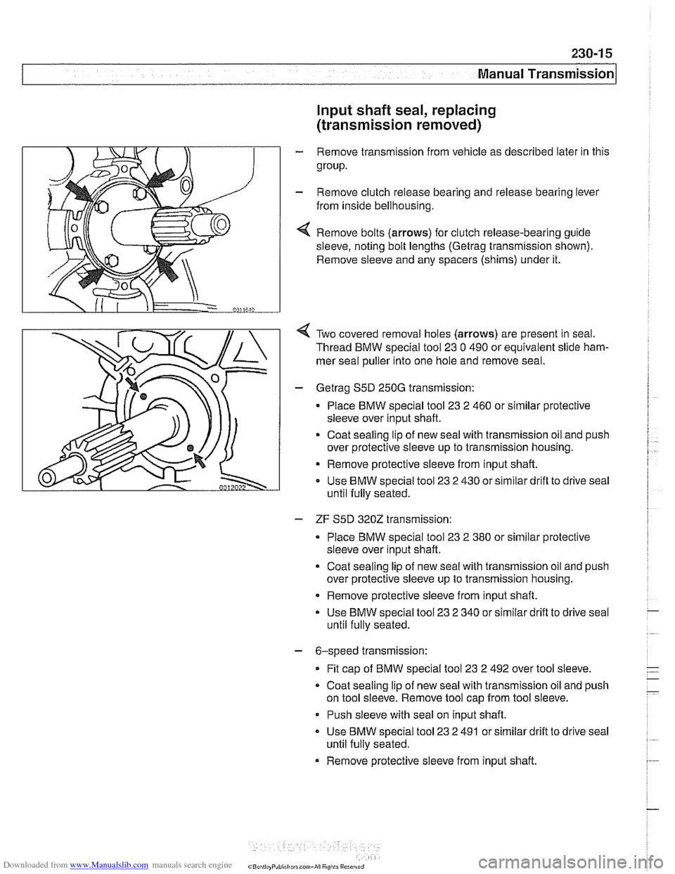
4 Remove bolts (arrows) for clutch release-bearing guide
sleeve, noting bolt lengths
(Getrag trensmission shown).
Remove sleeve and any spacers (shims) under it.
Two covered removal holes (arrows) are present in seal.
Thread BMW special tool
23 0 490 or equivalent slide ham-
mer seal puller into one hole and remove seal.
- Getreg S5D 250G transmission:
Place BMW special tool
23 2 460 or similar protective
sleeve over input shaft.
Coat sealing lip of new
seel with trensmission oil and push
over protective sleeve up to transmission housing.
Remove protective sleeve from input shaft.
Use BMW special tool
23 2 430 or similar drifl to drive seal
until fully seated.
- ZF S5D 3202 transmission:
Place BMW special tool
23 2 380 or similar protective
sleeve over input shaft.
Coat sealing lip of new seal with transmission oil and push
over protective sleeve up to transmission housing.
* Remove protective sleeve from input shaft.
Use BMW special tool
23 2 340 or similar drift to drive seal
until fully seated.
- 6-speed transmission:
Fit
cap of BMW special tool 23 2 492 over tool sleeve.
Coat sealing
lip of new seal with transmission oil and push
on tool sleeve. Remove tool cap from tool sleeve.
- Push sleeve with seal on input shaft.
- Use BMW special tool 23 2 491 or similar drift to drive seel
until fully seated.
Remove protective sleeve from input shaft.
Page 580 of 1002
Downloaded from www.Manualslib.com manuals search engine
Manual Transmission
- Thoroughly clean guide sleeve mounting bolts, sealing sur-
faces, and threads. Apply
Loctite8243 or equivalent thread
locking compound to guide sleeve bolts. Reinstall guide
sleeve and
spacer(s).
Tightening torques
Guide sleeve to transmission case
M6 10 Nm (89 in-lb)
* M8 x 22 18 Nm (13 ft-lb)
- Max30 25 Nm (18 ft-lb)
- Reinstall transmission.
TRANSMISSION REMOVAL AND
~NSTALLATION
Removal and installation of the transmission is best accorn-
plished on a lifl using a transmission jack.The engine must be
supported using appropriate support equipment. This allows
the engine to pivot on its mounts to access the upper
Torx-
head bolts at the bellhousing.
WARNING-
Male sure the car is stable and well supported at all times.
Use a professional aulomorive lift or jack slanos des~gned
lor the purpose. A floor jack is nor adequare supporr.
The removal of the transmission may upset the balance
of the vehicle on a
lifl.
Transmission, removing and installing
- Disconnect negative (-) cable from battery.
CAUTION-
Prior to disconnecting the battery, read the battery discon-
nection cautions given
in 001 Warnings and Cautions.
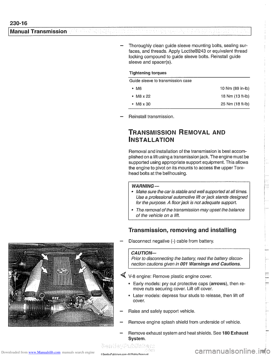
V-8 engine: Remove plastic engine cover.
Early models: pry out protective caps (arrows), then re-
move nuts securing cover. Lift off cover.
Later models: depress four studs to release, then
lift off
cover.
- Raise and safely support vehicle
- Remove engine splash shield from underside of vehicle
- Remove exhaust system and heat shields. See 180 Exhaust
System.