jack BMW 540i 1998 E39 User Guide
[x] Cancel search | Manufacturer: BMW, Model Year: 1998, Model line: 540i, Model: BMW 540i 1998 E39Pages: 1002
Page 333 of 1002
![BMW 540i 1998 E39 User Guide Downloaded from www.Manualslib.com manuals search engine
-- . - .. . - Lubrication system]
- Remainder of installation is reverse of removal.
Replace self-locking nuts when reinstalling front BMW 540i 1998 E39 User Guide Downloaded from www.Manualslib.com manuals search engine
-- . - .. . - Lubrication system]
- Remainder of installation is reverse of removal.
Replace self-locking nuts when reinstalling front](/img/1/2822/w960_2822-332.png)
Downloaded from www.Manualslib.com manuals search engine
-- . - .. . - Lubrication system]
- Remainder of installation is reverse of removal.
Replace self-locking nuts when reinstalling front suspen-
sion components.
Use new oil dipstick tube sealing O-ring.
After adding engine oil, start and run engine. Raise engine
speed to 2,500 rpm until oil pressure warning light goes out
(about 5 seconds).
NOTE-
BMW does not specify a front end alignment following this
procedure.
Tightening torques Front subfrarne to body rail
(M12, use new bolts)
8.8 grade
10.9 grade
12.9 grade 77 Nrn
(57 ft-lb)
105 Nrn (77 ft-lb)
110 Nrn (81 ft-lb)
Stabilizer bar link to stabilizer bar
65 Nrn (48 ft-lb)
Steering shaft universal joint clamping bolt
(use new bolt)
19 Nrn (14 it-lb)
Lower oil pan, removing and installing (V-8)
- The V-8 engine is equipped with a 2-piece oil pan. The fas-
teners in
V-8 engine oil pump assembly, including the
sprocket retaining nut, are known to loosen and fall off into
the oil pan. Be sure to install these fasteners with Loctite
O
or equivalent thread locking product and torque to specifica-
tions.
CAUTION-
It is recommended that the oil pump retaining bolts and oil
pump drive sprocket retaining nut tightening torque be
checkedany time the
oilpan is removed.
- Raise car and place securely on jack stands.
WARNING-
Make sure the car is stable and well supported at all times.
Use a professional automotive lift
orjack stands designed for
- Remove splash shield from under engine.
- Drain engine oil
- On cars with automatic transmission, remove ATF cooler line
brackets from oil pan.
Page 358 of 1002
Downloaded from www.Manualslib.com manuals search engine
.-
ignition System
Disabling ignition system
The ignition system operates in a lethal voltage range and
should be disabled any time engine service or repair work is
being done that requires the ignition to be switched on.
The engine management system can be disabled by remov-
ing the DME main relay. The relay is located in the electronics
box (E-box) in the left rear of the engine
compartment, be.
neath the interior microfilter housing.
CAUTION- Relay locations may
vary. Use care when identifying relays.
See
610 Electrical Component Locations.
Checking for spark
CAUTION-
If
a spark test is done incorrecth damage to the Engine Con-
trol Module
(ECM) or the ignition coils may result.
NOTE-
Spark plug replacement is covered in 020 Maintenance.
Check~ng for spark is d~fflcult on englnes wlth d~str~butorless
ignition systems.
Try removing the spark plugs and inspecting for differences between them.
A poor-firing plug may be wet with fuel and/or ~. - ~
black and sooty, but not always. If a coil is not operating, the
engine management system will electrically disable the fuel
injector to that cylinder. The key is to look for differences be-
tween cylinders.
Ignition coil assembly, testing and
replacing
C4 UTION-
Use a digital multimeter for the following tests. I
- Remove plastic engine cover from top of valve cover by pry-
ing off bolt covers and removing cover mounting bolts.
- Raise car slowly while constantly checking position of jack
and car.
- Disconnect harness connector from coil. Connect multimeter
between terminal 15
(+) in connector and ground.
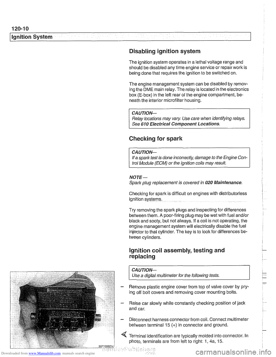
4 Terminal identification are typically molded into connector. In
photo, terminals are from left to right: 1,
4a, 15.
Page 378 of 1002
Downloaded from www.Manualslib.com manuals search engine
Battery, Starter, Alternator
Water-cooled alternator
The water-cooled alternator, used on 1999 and later M62 TU
engines, is a sealed unit housed inside the engine block wa-
ter jacket. It is cooled via the engine cooling system. It is a
"brushless" sealed unit that cannot be serviced. Maintaining
consistent alternator temperatures increases the life span of
the alternator, and elimination of the alternator cooling fan re-
duces alternator noise
significantly.
The M62 TU water-cooled alternator incorporates load start
reduction. This function is intended to shorten the duration of
engine starting, particularly at low ambienttemperatures. The
current load is limited to
20 amps during starting in order to re-
duce alternator braking torque on the engine. Following the
current limiting phase, full power output is then progressively
reached.
Charging system diagnostics requires special test equip-
ment. If the test equipment is not available, charging system
fault diagnosis can be performed by an authorized
BMW
dealer or other qualified repair shop. See Table a. Battery,
alternator and starter troubleshooting for general electri-
cal component troubleshooting.
Before checking the alternator, make sure the battery is fully
charged and capable of holding a charge. Check that the bat-
tery terminals are clean and tight and the alternator drive belt
is properly tensioned and not severely worn.
NOTE-
Some model require up to 15 second to reacli full alternator
output.
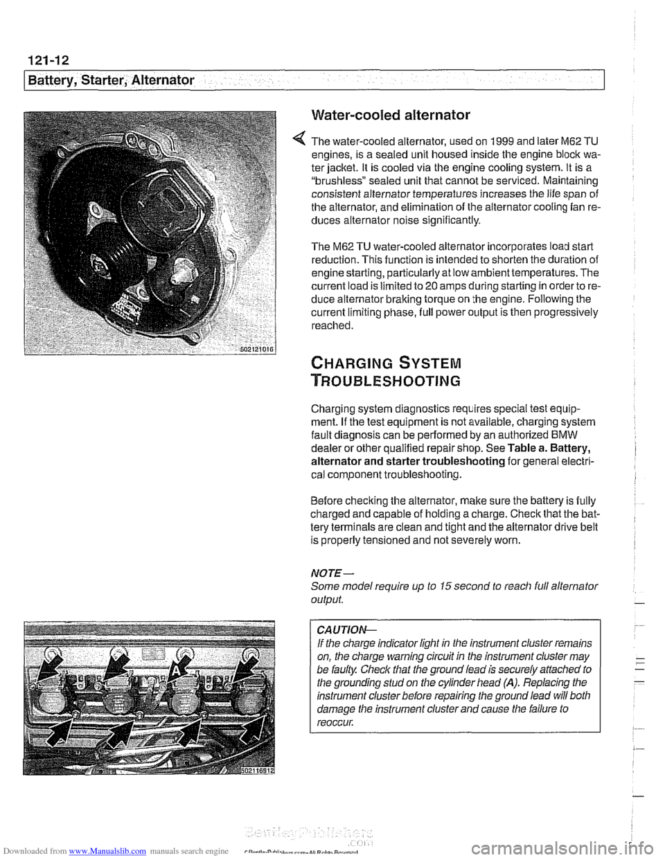
CA UTIOG
If the charge indicator light in the instrument cluster remains
on, the charge warning circuit in the instrument cluster may
be faulty. Check that the ground lead is securely
affached to
the grounding stud on the cylinder head
(A). Replacing the
instrument cluster before repairing the ground lead will both
damage the instrument cluster and cause the failure to
reoccur.
Page 382 of 1002
Downloaded from www.Manualslib.com manuals search engine
121-16
Battery, Starter, Alternator
- installation is reverse of removal.
Tightening torques Belt tensloner to engine block
M8 (8.8 grade) 22
Nm (16 ft-ib)
Fan clutch to coolant pump
with BMW special tool 11
5 040 30 Nm (22
ft-lb)
without BMW special tool
11 5 040 40 Nm
(29 ft-ib)
Pulley to alternator 70
Nm (44 ft-lb)
Terminal 30
(B+) wire to alternator (M8) 13 Nm (10 ft-ib)
Alternator, removing and installing
(M62 engine, air cooled)
A replacement alternator should have the same rating as the
original. Alternator manufacturer and ampere rating are nor-
mally
marked on the alternator housing.
- Disconnect negative (-) battery cable.
CAUTION-
Prior to disconnecting the battery, read the battery discon-
nection cautions
001 General Warnings and Cautions.
- Remove cooling fan and alternator drive belt. See 020 Main-
tenance.
- Pry out trim caps and remove fasteners from plastic cover on
left head. Lift off cover.
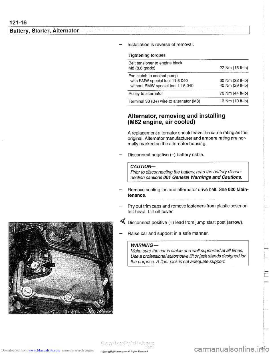
Disconnect positive
(+) lead from jump start post (arrow).
Raise car and support in a safe manner.
WARNING-
Make sure the car is stable and well supported at aN times.
Use a professional automotive lift
orjack stands designed for
the purpose.
A floorjack is not adequate support.
Page 384 of 1002
Downloaded from www.Manualslib.com manuals search engine
121-18
I Battery, Starter, Alternator
Alternator, removing and installing
(M62 TU engine, water cooled)
V-8 models produced after 9/98 are equipped with a water
cooled alternator.
CAUTION-
Allow engine to cool before removing alternator as coolant
will
escape from the alternator water jacket.
- Disconnect negative (-) battery cable
CAUTION- Prior to disconnecting the
battew read the battery discon-
nection cautions given in
001 General Warnings and Cau-
tions.
- Remove radiator cooling fan and fan shroud. See 170 Radi-
ator and Cooling System.
- Drain engine cooling system. See 170 Radiator and Cool-
ing System.
- Remove alternator drive belt. See 020 Maintenance.
- Disconnect battery lead (terminal 30 or B+) and two-pin har-
ness connector from front of alternator.
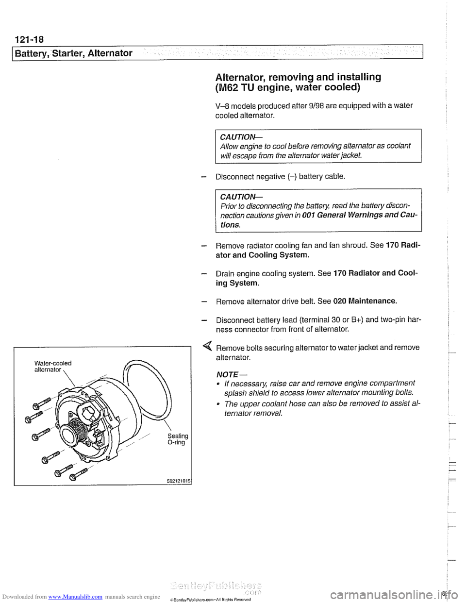
I < Remove bolts securing alternator to water jacket and remove
aling ring
alternator.
NOTE- If necessary, raise car and remove engine compartment
splash shield to access lower alternator mounting bolts.
The upper coolant hose can also
be removed to assist al-
ternator removal.
Page 386 of 1002
Downloaded from www.Manualslib.com manuals search engine
I Battery, Starter, Alternator
- Check for battery voltage at terminal 50 of starter motor with
key in start position. If voltage is not present, check wiring be-
tween ignition switch and starter terminal. Check the EWS
system and other inputs that disrupt terminal
56 to the start-
er. See ELE Electrical
Wiring Diagrams. If voltage is
present and no other visible wiring faults can be found, prob-
lem is most likely in starter motor.
Starter, removing and installing
(6-cylinder engine)
The starter is removed from below. Access to starter bolts is
difficult. Be sure to have the proper tools on hand before pro-
ceeding.
NOTE-
Access to the starter wiring is very limited. Forbetteraccess,
it may be necessary to remove the intake manifold.
- Disconnect negative (-) battery cable.
CAUTIOI\C
Prior to disconnecting the battern read the baltery discon-
nection cautions
in OOlGeneral Cautions and Warnings.
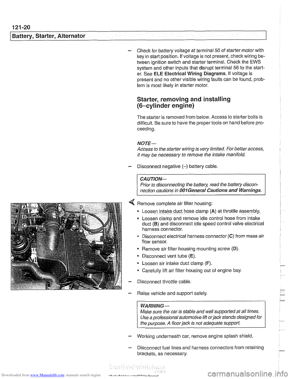
Remove complete air filter hous~ng:
Loosen intake duct hose clamp (A) at throttle assembly.
Loosen clamp and remove idle control hose from intake
duct
(B) and disconnect idle speed control valve electrical
harness connector.
Disconnect electrical harness connector
(C) from mass air
flow sensor.
Remove air filter housing mounting screw (D)
Disconnect vent tube
(E).
Loosen air intake duct clamp (F).
Carefully lift air filter housing out of engine bay.
Disconnect throttle cable.
Raise vehicle and support safely.
WARNING-
Make sure the car is stable and well supported at all times.
Use a professional automotive
lift orjack stands designed for
the purpose. A
floorjaclc is not adequate support
- Working underneath car, remove engine splash shield
- Disconnect fuel lines and harness connectors from retaining
brackets, as necessary.
Page 387 of 1002
Downloaded from www.Manualslib.com manuals search engine
Battery, Starter, ~lternatorl
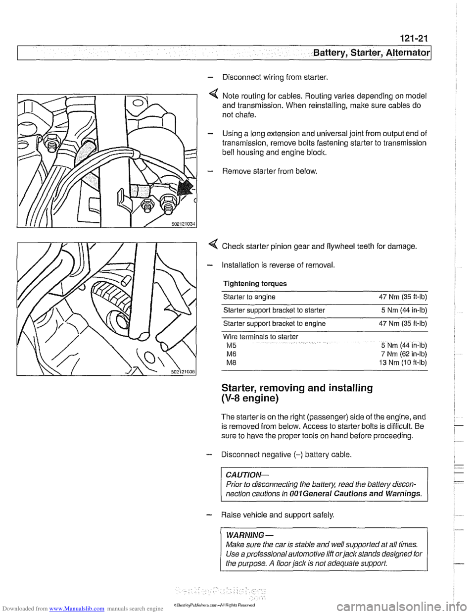
- Disconnect wiring from starter.
4 Note routing for cables. Routing varies depending on model
and transmission. When reinstalling, make sure cables do
not chafe.
- Using a long extension and universal joint from output end of
transmission, remove bolts fastening starter to transmission
bell housing and engine block.
- Remove starter from below
4 Checlc starter pinion gear and flywheel teeth for damage.
- Installation is reverse of removal.
Tightening torques
Starter to engine 47 Nrn (35 It-lb)
Starter sipport bracket to starter 5 Nrn (44 in-lb)
Starter support
bracket to engine 47 Nrn (35 ft-lb)
Wlre terminals to slarter
M5 5 Nrn (44 in-lb)
M6 7 Nrn (62 in-lb)
M8 13 Nrn (10 ft-lb)
Starter, removing and installing
(V-8 engine)
The starter is on the right (passenger) side of the engine, and
is removed from below. Access to starter bolts is difficult. Be
sure to have the proper tools on hand before proceeding.
- Disconnect negative (-) battery cable
CA UTIOW-
Prior to disconnecting the battery, read the battev discon-
nection cautions in
OOlGeneral Cautions and Warnings. -
- Raise vehicle and support safely.
/ WARNING- 1 ~ ~~ ~~ ~~~ ~
Make sure the car is stable and well supported at all times.
Use a professional automotive lift orjacltstands designed for
I the purpose. A floor jack is not adequate support I
Page 491 of 1002
Downloaded from www.Manualslib.com manuals search engine
Fuel Tank and Fuel pump/
- Remove suction hose from tank filler neck carefully to avoid
damaging filler neck baffle plate.
CAUTION-
After finishing repairs but before starling engine, be sure
there is at least
5 liters (1.5 gallons) of fuel in tanlc. The fuel
pump will be damaged if run without fuel.
Fuel tank, removing and installing
- Remove fuel tank filler cap and drain tank as described
earlier.
- Disconnect negative cable from battery.
CAUTION-
Prior to disconnecting the battea read the battery discon-
nection cautions given in
001 General Cautions and
Warnings.
- Remove rear seat bottom cushion. Peel forward lip of carpet
from beneath seat cushion and carefully peel back insulation
to expose fuel tank access cover on left and right sides. Re-
move covers.
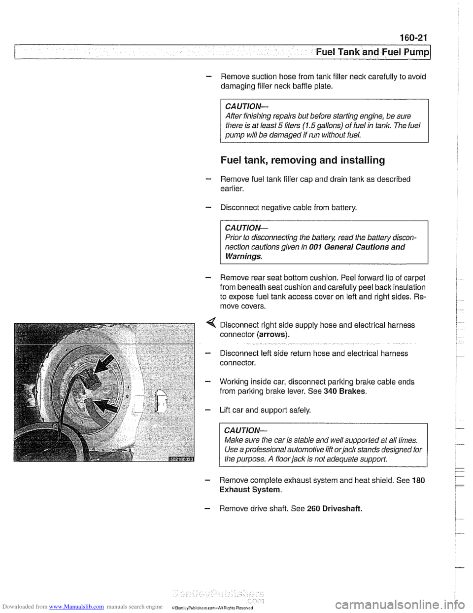
Disconnect right side supply hose and
electr~cal harness
connector (arrows).
D~sconnect left side return hose and electrical harness
connector.
Working inside car, disconnect parking
bralte cable ends
from parking brake lever. See
340 Brakes.
Lift car and support safely.
Make sure the car is stable and
we/ supported at all times.
Use a professional automotive lift
orjack stands designed for
the purpose. A floorjaclc is not adequate support.
- Remove complete exhaust system and heat shield. See 180
Exhaust System.
- Remove drive shaft. See 260 Driveshaft
Page 493 of 1002

Downloaded from www.Manualslib.com manuals search engine
.- Fuel Tank and Fuel pump( -
Fuel expansion tank, removing
and installing
- Raise rear end of car and support safely.
CA U TIOG
Make sure the car is stable and well supported at all times.
Use a professional automotive lift
orjack stands designed for
the
ouroose. A floor iack is not adequate support
- Remove left rear wheel and wheel housing inner shield.
4 Remove plastic nut (A) and disconnect hose (B).
4 Tilt vent tank down and loosen or cut off hose clamps
(arrows). Pull hoses off fittings.
- Release vacuum line loclting clips and remove tank
- Installation is reverse of removal. Use new hose clamps.
Tightening torques
Hose clamp 8 - 13 mm dia. 2 Nrn (18 in-lb)
Hose clamp 13 - 16 mm dia. 3 Nm (27 in-lb)
Hose clamp
42 - 48 mm dia. 4 Nm (36 in-lb)
Page 494 of 1002
Downloaded from www.Manualslib.com manuals search engine
Fuel Tank and Fuel Pump 1
Activated carbon canister I fuel tank leak
detection unit
(LDP or DMTL), removing . . -
and installing
- Raise rear end of car and support safely.
CAUTION-
Make sure the car is stable and well supported at all times.
Use a professional automotive lift
orjack stands designed for
the purpose.
A floor jack is not adequate support.
- Remove left rear wheel and inner fender panel
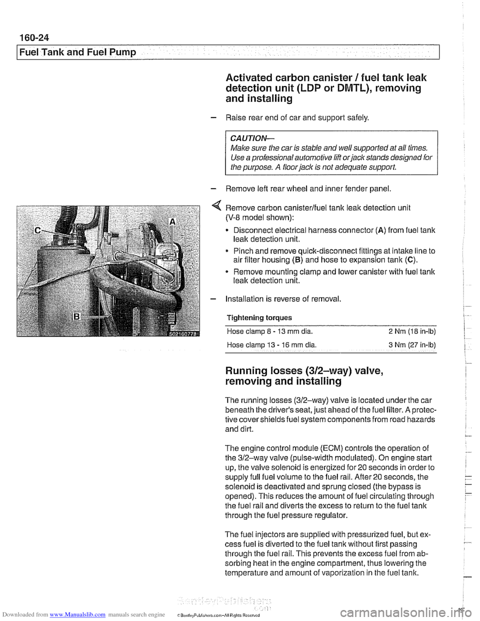
Remove carbon canisterlfuel tank leak detection unit
(V-8 model shown):
Disconnect electrical harness connector
(A) from fuel tank
leak detection unit.
Pinch and remove quick-disconnect fittings at intake line to
air filter housing
(5) and hose to expansion tank (C).
* Remove mounting clamp and lower canister with fuel tank
leak detection unit.
Installation is reverse of removal.
Tightening
torques
Hose clamp 8 - 13 mm dia. 2 Nrn (18 in-lb)
Hose clamp
13 - 16 rnm dia 3 Nm (27 in-lb)
Running losses (312-way) valve,
removing and installing
The running losses (312-way) valve is located under the car
beneath the driver's seat, just ahead of the fuel filter. A protec-
tive covershieldsfuel system components from road hazards
and dirt.
The engine control module
(ECM) controls the operation of
the 312-way valve (pulse-width modulated). On engine start
up, the valve solenoid is energized for 20 seconds in order to
supply full fuel volume to the fuel rail.
After20 seconds, the
solenoid is deactivated and sprung closed (the bypass is
opened). This reduces the amount of fuel circulating through
the fuel rail and diverts the excess to return to the fuel tank
through the fuel pressure regulator.
The fuel injectors are supplied with pressurized fuel, but ex-
cess fuel is diverted to the fuel tank without first passing
through the fuel rail. This prevents the excess fuel from ab-
sorbing heat in the engine compartment, thus lowering the
temperature and amount of vaporization in the fuel tank.