engine BMW 540i 1998 E39 Workshop Manual
[x] Cancel search | Manufacturer: BMW, Model Year: 1998, Model line: 540i, Model: BMW 540i 1998 E39Pages: 1002
Page 221 of 1002
Downloaded from www.Manualslib.com manuals search engine
Cylinder Head and valvetrain1
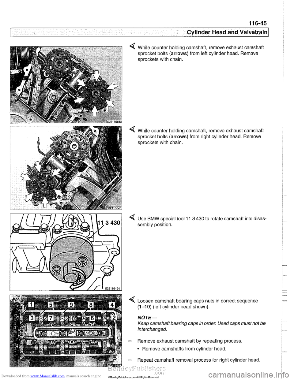
While counter holding camshaft, remove exhaust camshaft
sprocket bolts
(arrows) from left cylinder head. Remove
sprocltets with chain.
< While counter holding camshaft, remove exhaust camshaft
sprocket bolts
(arrows) from right cylinder head. Remove
sprocltets with chain.
4 Use BMW special tool 11 3 430 to rotate camshaft into disas-
sembly position.
4 Loosen camshaft bearing caps nuts in correct sequence
(1-10) (left cylinder head shown).
NOTE -
Keep camshaft bearing caps in order. Used caps must not be
interchanged.
- Remove exhaust camshaft by repeating process.
0 Remove camshafts from cylinder head.
- Repeat camshaft removal process for right cylinder head.
Page 222 of 1002
Downloaded from www.Manualslib.com manuals search engine
11 6-46
/cylinder Head and Valvetrain
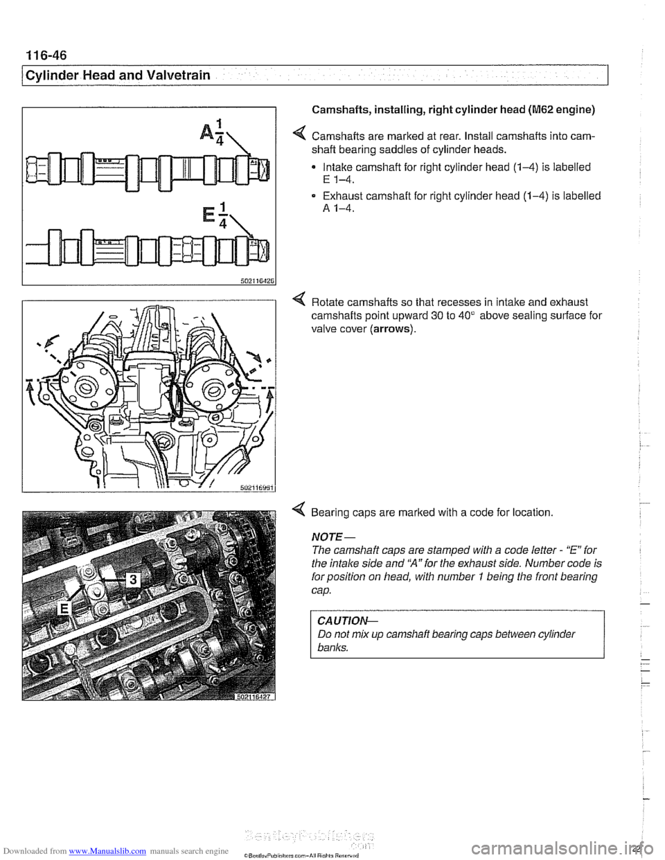
I I Camshafts, installing, right cylinder head (M62 engine)
I
1
A: / Camshafts are marked at rear. Install camshafts into cam-
shaft bearing saddles of cylinder heads.
Intake camshaft for right cylinder head
(14) is labelled
E 1-4.
Exhaust camshaft for right cylinder head (1-4) is labelled
A 1-4.
4 Rotate camshafts so that recesses in Intake and exhaust
camshafts
polnt upward 30 to 40' above seal~ng surface for
valve cover (arrows).
4 Bearing caps are marked with a code for location.
NOTE-
The camshaft caps are stamped with a code letter - "E" for
the intake side and
'N" for the exhaust side. Number code is
forposition on head, with number
7 being the front bearing
cap.
CAUTION--
Do not mix up camshafi bearing caps between cylinder
banks.
Page 223 of 1002
Downloaded from www.Manualslib.com manuals search engine
1 Cvlinder Head and valvetrain1
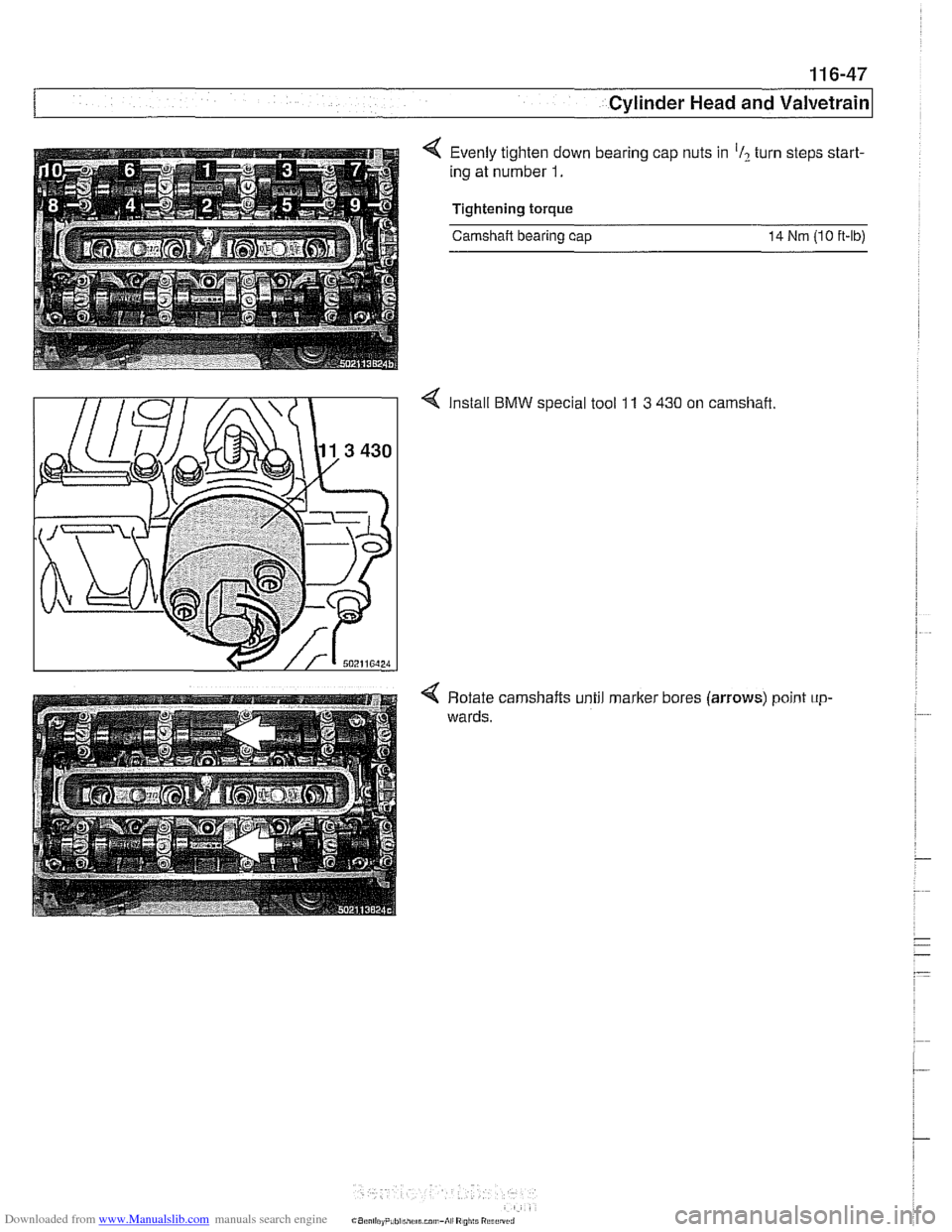
Evenly tighten down bearing cap nuts in 'I? turn steps start-
ing at number
1.
Tightening torque
Camshaft bearing cap 14 Nm (10 ft-lb)
BMW special tool 11 3 430 on camshaft.
4 Rotate camshafts until marker bores (arrows) point up-
wards.
Page 224 of 1002
Downloaded from www.Manualslib.com manuals search engine
1 16-48
/Cylinder Head and Valvetrain
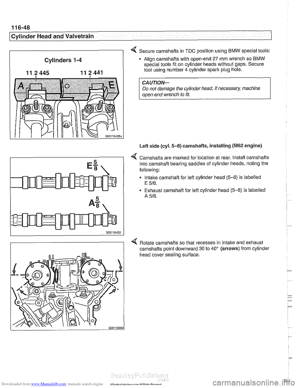
Cylinders
1-4
11 2 445 11 2441
4 Secure camshafts in TDC position using BMW special tools:
Align camshafts with open-end
27 mm wrench so BMW
special tools fit on cylinder heads without gaps. Secure
tool using number 4 cylinder spark plug hole.
Do not damage the cylinder head. If
necessa& machine
open-end wrench to fit.
Left side (cyl.
5-8) camshafts, installing (M62 engine)
4 Camshafts are marked for location at rear. Install camshafts
into camshaft bearing saddles of cylinder heads, noting the
following:
Intake camshaft for left cylinder head
(5-8) is labelled
E 518.
Exhaust camshaft for left cylinder head (5-8) is labelled
A
518.
4 Rotate camshafts so that recesses in intake and exhaust
camshafts point downward 30 to 40" (arrows) from cylinder
head cover sealing surface.
Page 225 of 1002
Downloaded from www.Manualslib.com manuals search engine
- -
Cylinder Head and valvetrain1
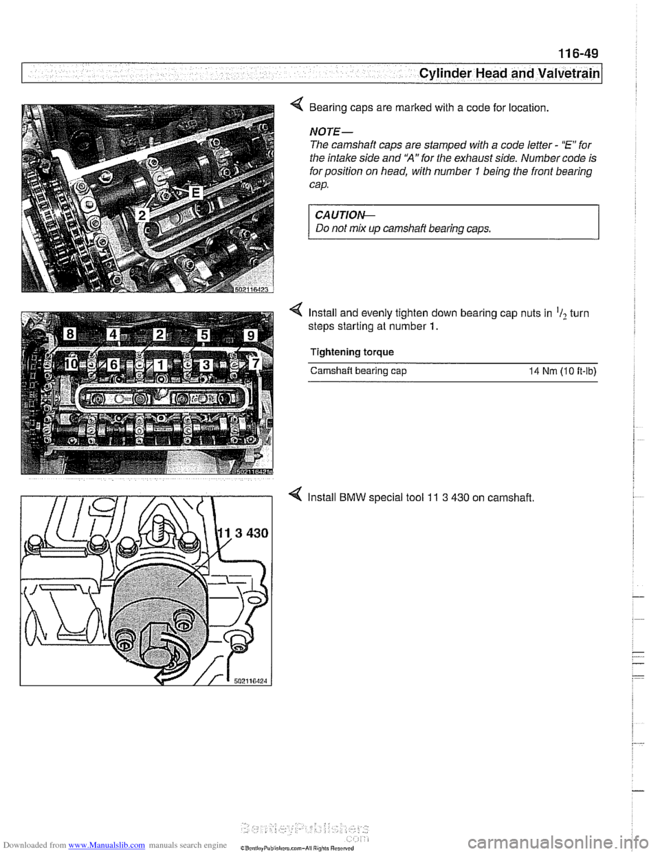
4 Bearing caps are marked with a code for location.
NOTE-
The camshaft caps are stamped with a code letter - "E for
the intake side and
'HA" for the exhaust side. Number code is
for position on head, with number
1 being the front bearing
cap.
CA UTIOI\C
Do not mix up camshaft bearing caps.
Install and evenly tighten down bearing cap nuts in
'I2 turn
steps starting at number
1.
Tightening torque
Camshaft bearing cap 14 Nrn (10 ft-lb)
4 Install BMW special tool 11 3 430 on camshaft.
Page 226 of 1002
Downloaded from www.Manualslib.com manuals search engine
1 16-50
/Cylinder Head and Valvetrain
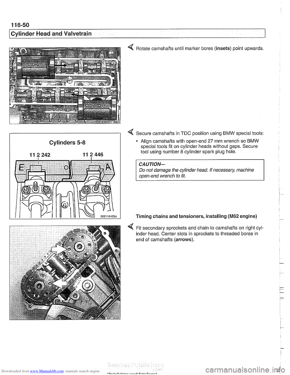
4 Rotate camshafts until marker bores (insets) point upwards,
4 Secure camshafts in TDC position using BMW special tools:
Cylinders 5-8 Align camshafts w~th open-end 27 mm wrench so BMW
special tools fit on cylinder heads without gaps. Secure
11 2 242 11 2 446 I tool using number 8 cylinder spark plug hole.
CAUTION-
Do not damage the cylinder head. If necessary, machine
open-end wrench to
fit.
Timing chains and tensioners, installing (M62 engine)
4 Fit secondary sprocltets and chain to camshafts on right cyl-
inder head. Center slots in sprocltets to threaded bores in
end of camshafts (arrows).
. .
Page 227 of 1002
Downloaded from www.Manualslib.com manuals search engine
- -.
Cylinder Head and valvetrain1
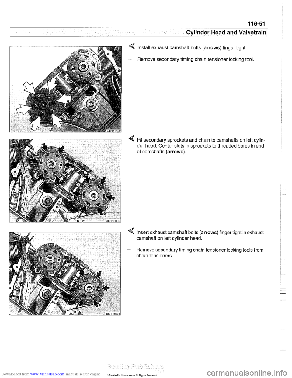
Install exhaust camshaft bolts (arrows) finger tight.
Remove secondary timing chain tensioner
loclting tool.
< Fit secondary sprockets and chain to camshafts on left cylin-
der head. Center slots in sprocltets to threaded bores in end
of camshafts
(arrows).
Insert exhaust camshaft bolts (arrows) finger tight in exhaust
camshaft on left cylinder head.
Remove secondary timing chain tensioner locking tools from
chain tensioners.
Page 228 of 1002
Downloaded from www.Manualslib.com manuals search engine
ICylinder Head and Valvetrain -.
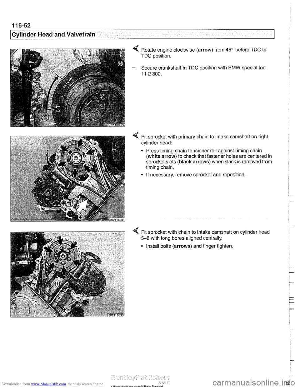
Rotate engine clockwise (arrow) from 45" before TDC to
TDC position.
Secure crankshaft in
TDC position with BMW special tool
11 2 300.
4 Fit sprocket with primary chain to intaite camshaft on right
cylinder head:
Press timing chain tensioner rail against timing chain
(white arrow) to check that fastener holes are centered in
sprocket slots (black arrows) when slack is removed from
timing chain.
If necessary, remove sprocket and reposition.
Fit sprocket with chain to intake camshaft
5-8 with long bores aligned centrally.
Install bolts (arrows) and finger tighten cylinder
head
Page 229 of 1002
Downloaded from www.Manualslib.com manuals search engine
Cylinder Head and valvetrain'
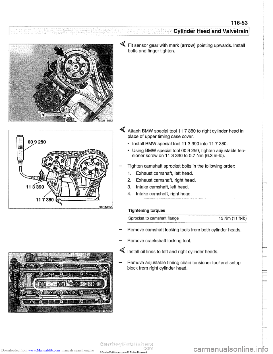
Fit sensor gear with mark (arrow) pointing upwards. Install
bolts and finger tighten.
4 Attach BMW special tool 11 7 380 to right cylinder head in
place of upper timing case cover.
Install BMW special tool
11 3 390 into 11 7 380.
Using BMW special tool 00 9 250, tighten adjustable ten-
sioner screw on
11 3 390 to 0.7 Nm (6.3 in-lb).
- T~ghten camshaft sprocket bolts in the following order:
1. Exhaust camshaft, left head.
2. Exhaust camshaft, right head.
3. Intake camshaft, left head.
4. Intake camshaft, right head.
Tightening torques Sprocket
to camshaft flange 15 Nm (I 1 ft-lb)
- Remove camshaft locking tools from both cylinder heads.
- Remove crankshaft locking tool.
4 lnstall oil lines to left and right cylinder heads.
- Remove adjustable timing chain tensioner tool and setup
block from right cylinder head.
Page 230 of 1002
Downloaded from www.Manualslib.com manuals search engine
11 6-54
Cylinder Head and Valvetrain
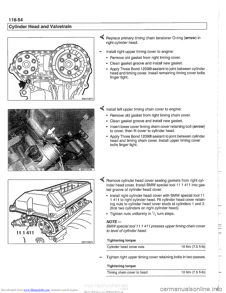
Replace primary timing chain tensioner O-ring (arrow) in
right cylinder head.
- lnstall right upper timing cover to engine:
Remove old gasket from right timing cover.
Clean gasket groove and install new gasket.
Apply Three Bond
12098sealant to joint between cylinder
head and timing cover. Install remaining timing cover bolts
finger tight.
lnstall left upper timing chain cover to engine:
Remove old gasket from right timing chain cover.
Clean gasket groove and install new gasket.
Insert lower cover timing chain cover retaining bolt (arrow)
to cover, then fit cover to cylinder head.
Apply Three Bond 12098 sealant to joint between cylinder
head and timing chain cover. lnstall upper timing cover
bolts finger tight.
4 Remove cylinder head cover sealing gaskets from right cyl-
inder head cover. lnstall BMW special tool 11
1 41 1 into gas-
ket groove of cylinder head cover.
lnstall right cylinder head cover with BMW special tool
11
1 41 1 to right cylinder head. Fit cylinder head cover retain-
ing nuts to cylinder head cover studs at cylinders
1 and 2
(first two cylinders on right cylinder head).
Tighten nuts uniformly in
'I2 turn steps.
NOTE-
BMW special tool 11 1 41 1 presses upper timing chain cover
to level of cylinder head.
Tightening torque Cylinder head cover nuts
10 Nm (7.5 n-lb)
- Tighten right upper timing cover retaining bolts in two passes.
Tightening torque
Timing chain cover to head
10 Nm (7.5 ft-lb)