Cylinder BMW 540i 1999 E39 Workshop Manual
[x] Cancel search | Manufacturer: BMW, Model Year: 1999, Model line: 540i, Model: BMW 540i 1999 E39Pages: 1002
Page 779 of 1002
Downloaded from www.Manualslib.com manuals search engine
Brakes
Master cylinder, removing and installing
CAUTlOI\C
Brake fluid is highly corrosive and dangerous to the environ-
ment. Dispose of it properly.
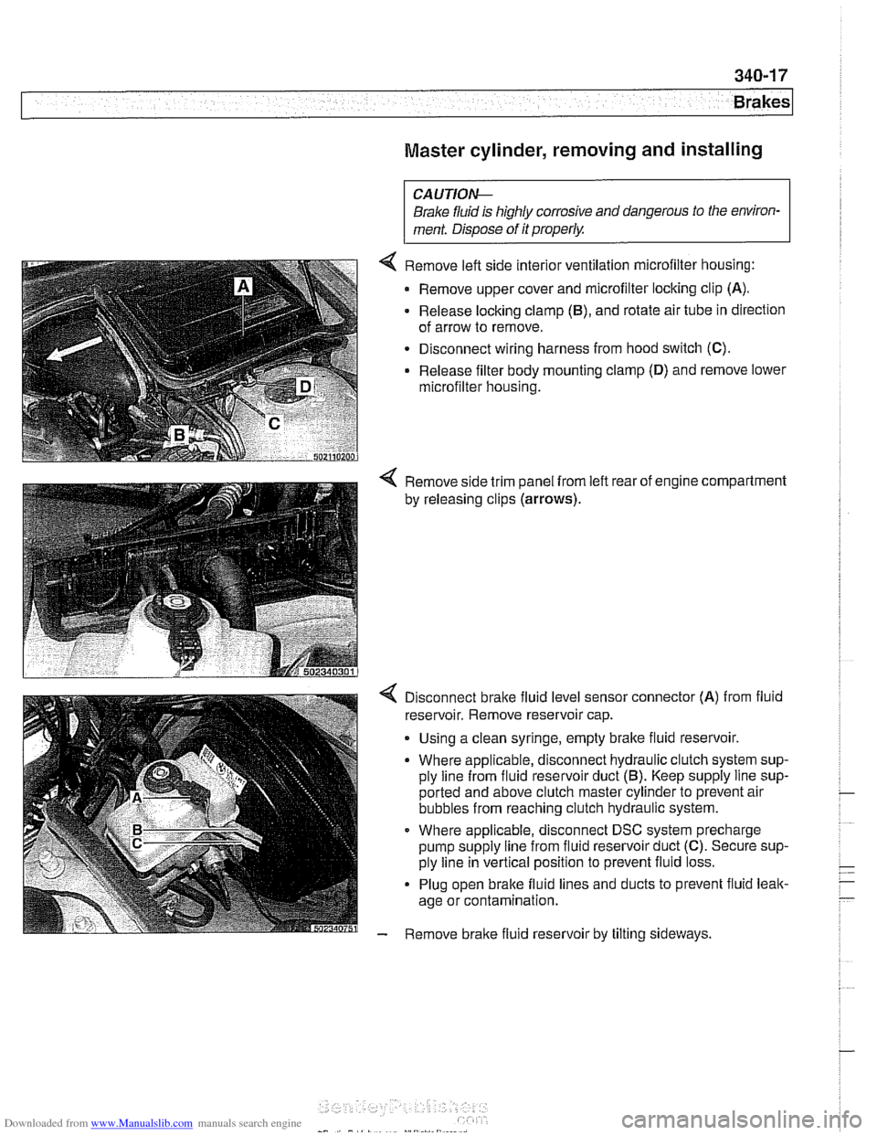
4 Remove left side interior ventilation microfilter housing:
Remove upper cover and microfilter locking clip
(A).
- Release locking clamp (B), and rotate air tube in direction
of arrow to remove.
Disconnect wiring harness from hood switch
(C).
Release filter body mounting clamp (D) and remove lower
microfilter housing.
4 Remove side trim panel from left rear of engine compartment
by releasing clips
(arrows).
4 Disconnect bralte fluid level sensor connector (A) from fluid
reservoir. Remove reservoir cap.
. Using a clean syringe, empty bralte fluid reservoir.
Where applicable, disconnect hydraulic clutch system sup-
ply line from fluid reservoir duct
(5). Keep supply line sup-
ported and above clutch master cylinder to prevent air
bubbles from reaching clutch hydraulic system.
Where applicable, disconnect DSC system precharge
pump supply line from fluid reservoir duct
(C). Secure sup-
ply line in vertical position to prevent fluid loss.
Plug open brake fluid lines and ducts to prevent fluid leak-
age or contamination.
- Remove brake fluid reservoir by tilting sideways.
Page 780 of 1002
Downloaded from www.Manualslib.com manuals search engine
.- -
Brakes
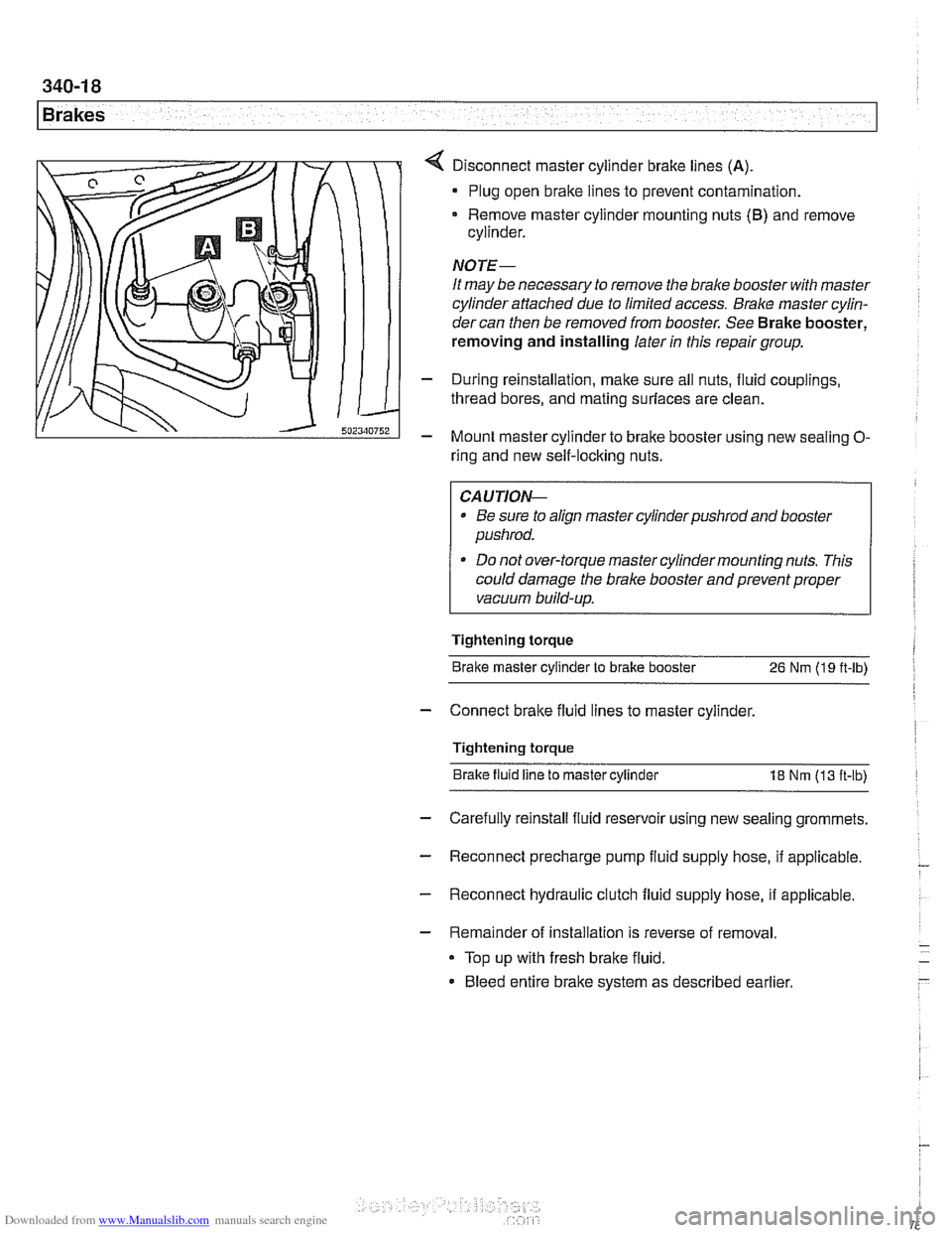
Disconnect master cylinder brake lines (A)
Plug open brake lines to prevent contamination.
Remove master cylinder mounting nuts
(6) and remove
cylinder.
NOTE-
It may be necessary to remove the brake booster with master
cylinder attached due to limited access.
Bralce master cylin-
dercan then be removed from booster. See Brake booster,
removing and installing later
in this repair group.
- During reinstallation, make sure all nuts, fluid couplings,
thread bores, and mating surfaces are clean.
- Mount master cylinder to bralte booster using new sealing O-
ring and new self-locking nuts.
CAUTIOI\C
* Be sure to align master cylinderpushrod and booster
pushrod.
* Do not over-torque master cylinder mounting nuts. This
could damage the brake booster and prevent proper
vacuum build-up.
Tightening torque Brake master cylinder to brake booster
26 Nm (19 ft-lb)
- Connect bralte fluid lines to master cylinder.
Tightening torque Brake fluid line to master cylinder
18 Nm (13 ft-lb)
- Carefully reinstall fluid reservoir using new sealing grommets.
- Reconnect precharge pump fluid supply hose, if applicable. -
- Reconnect hydraulic clutch fluid supply hose, if applicable.
- Remainder of installation is reverse of removal.
Top up with fresh brake fluid.
Bleed entire brake system as described earlier
Page 781 of 1002
Downloaded from www.Manualslib.com manuals search engine
Brakes
The brake booster is mounted to the bulkhead on driver's side
of the engine compartment, directly behind the brake master
cylinder. Intake manifold vacuum acts on a large diaphragm
in the brake booster to reduce brake pedal effort.
Brake booster check valve
The checlc valve in the bralte booster vacuum line prevents
contamination from engine backfires and other sources from
entering the bralte booster.
Location of
check valve varies, depending on year and mod-
el.
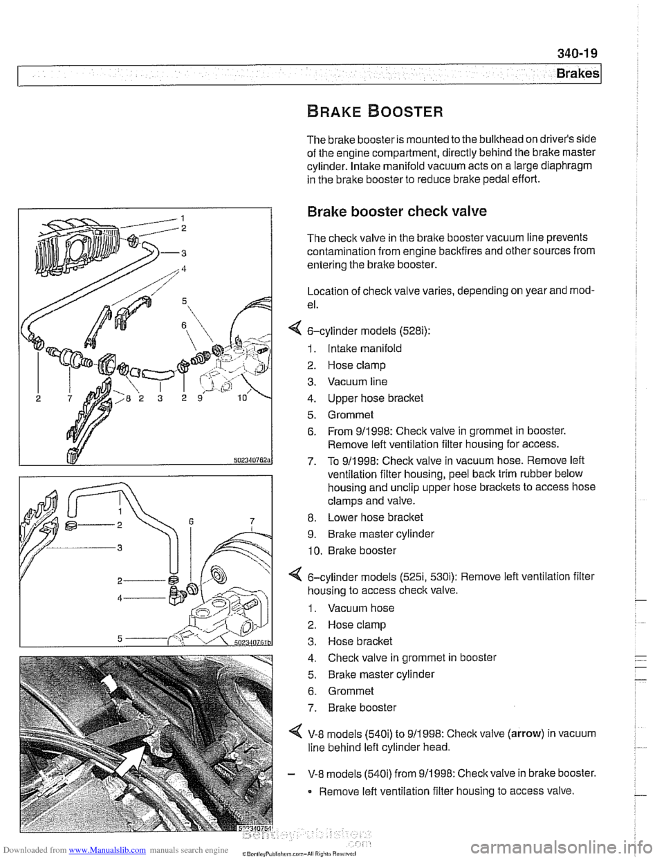
4 6-cylinder models (528i):
1. Intake manifold
2 Hose clamp
3. Vacuum line
4. Upper hose bracket
5. Grommet 6. From 911998: Check valve in grommet in booster.
Remove left ventilation filter housing for access.
7. To 911 998: Check valve in vacuum hose. Remove left
ventilation filter housing, peel back trim rubber below
housing and
unclip upper hose brackets to access hose
clamps and valve.
8. Lower hose
bracket
9. Brake master cylinder
10. Brake booster
< 6-cylinder models (525i, 530i): Remove left ventilation filter
housing to access
checlc valve.
1. Vacuum hose
2. Hose clamp
3. Hose bracket
4. Check valve in grommet in booster
5.
Braite master cylinder
6. Grommet
7. Brake booster
4 V-8 models (540i) to 911998: Check valve (arrow) in vacuum
line behind left cylinder head.
- V-8 models (540i) from 911998: Checkvalve in brake booster.
Remove left ventilation filter housing to access valve.
Page 782 of 1002
Downloaded from www.Manualslib.com manuals search engine
Brakes
- Pump brake pedal a few times to reduce vacuum in brake
booster. This makes removal of
check valve easier.
- Remove or loosen hose clamp(s) at check valve.
- Disconnect hoses. Remove valve to test or replace.
NOTE-
If valve is pressed into grommet in vacuum booster, pry it out
carefully.
- Reinstall valve using new hose clamps
NOTE-
Install the valve so that the molded arrow is pointing toward
the intake manifold.
Brake booster, removing and installing
CAUTIO&
All E39 vehicles sold in the USA are equipped with Antiloclc
Braking System (ABS) and either Automatic Stability Control
(ASC) or Dynamic Stability Control (DSC). In order for the
bralchg and stability controls to work properk if brake fluid
lines are disconnected and reconnected,
male sure that the
brake system is bled by an authorized BMW dealer or other
qualified repair facility using the BMW Service Tester: See
Brake Bleeding earlier in this group.
- Disconnect negative (-) cable from battery.
I CAUTION- I
Prior to disconnecting the battery read the battery discon-
nection cautions given in
001 General Cautions and
I Warnings. I
- Remove bralte master cylinder as described earlier.
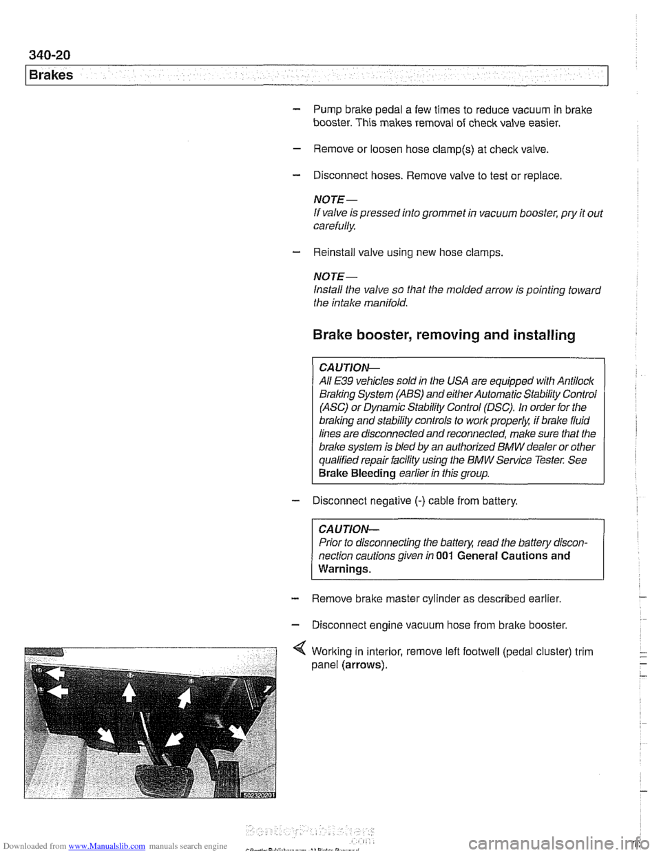
- Disconnect engine vacuum hose from bralte booster.
Page 783 of 1002
Downloaded from www.Manualslib.com manuals search engine
1 Brakes
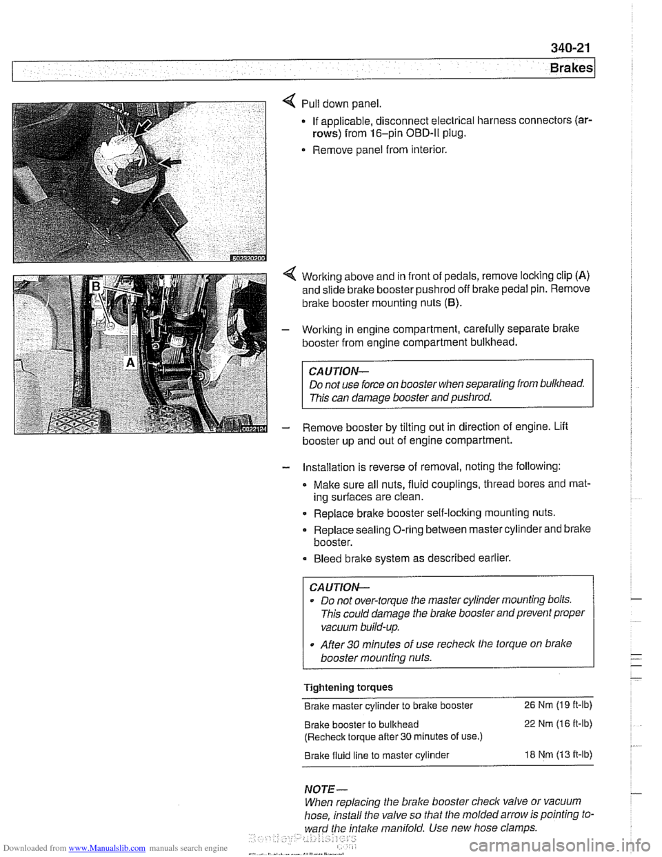
Pull down panel
If applicable, disconnect electrical harness
rows) from 16-pin OBD-ll plug.
Remove panel from interior. connectors
(ar-
Working
above and in front of pedals, remove locking clip (A)
and slide brake booster pushrod off bralte pedal pin. Remove
brake booster mounting nuts
(6).
Working in engine compartment, carefully separate bralte
booster from engine compartment bulkhead.
CAUTION-
Do not use force on booster when separating from bulkhead.
This can damage booster and pushrod.
Remove booster by tilting out in direction of engine. Lift
booster up and out of engine compartment.
- Installation is reverse of removal, noting the following:
Make sure all nuts, fluid couplings, thread bores and mat-
ing surfaces are clean.
Replace bralte booster self-locking mounting nuts.
Replace sealing O-ring between master cylinder and bralte
booster.
Bleed bralte system as described earlier.
CAUTION--
Do not over-torque tlie master cylinder mounting bolts.
This could damage the
bralce booster and prevent proper
vacuum build-up.
After
30 minutes of use recheclc the torque on bralce
booster mounting nuts.
Tightening torques
Brake master cylinder to brake booster
26 Nm (19 it-lb)
Brake booster to bulkhead 22 Nm (16 it-lb)
(Recheck torque after
30 minutes of use.)
Brake fluid line to master cylinder 18 Nm (13 it-lb)
NOTE-
When replacing the brake booster check valve or vacuum
hose, install the valve so that the molded arrow is pointing to-
ward the
fntalce manifold. Use new hose clamps
Page 797 of 1002
Downloaded from www.Manualslib.com manuals search engine
Body shell
Exterior and aerodynamics
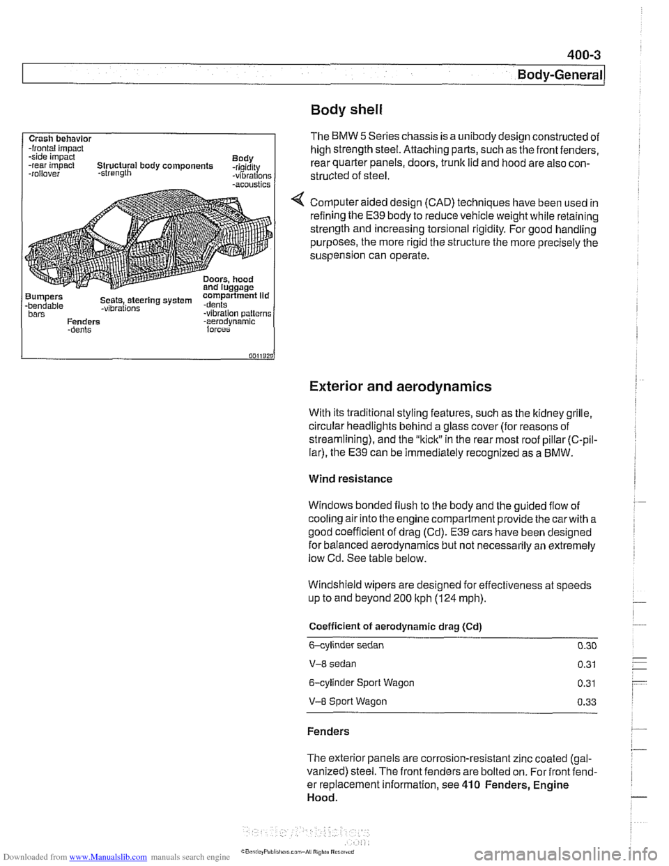
Crash behavlor -frontal impact
-side impact
Body
-rear impact Structural body components -rigidity
-rollover -strength -vibrations -acoustics
Bumpers compartment lid -bendable Seets,.steerlng system .dents -vibrations bars -vibration patterns
Fenders -aerodvnamic
With its traditional styling features, such as the ltidney grille.
circular headlights behind a glass cover (for reasons of
streamlining), and the
"kiclt" in the rear most roof pillar (C-pil-
lar), the E39 can be immediately recognized as a BMW.
The BMW 5 Series chassis is a unibody design constructed of
high strength steel. Attaching parts, such as the front fenders,
rear quarter panels, doors,
trunk lid and hood are also con-
structed of
steel.
Computer aided design (CAD) techniques have been used in
refining the
E39 body to reduce vehicle weight while retaining
strength and increasing torsional rigidity. For good handling
purposes, the more rigid the structure the more precisely the
suspension can operate.
Wind resistance
Windows bonded flush to the body and the guided flow of
cooling air into the engine compartment provide the
carwith a
good coefficient of drag (Cd).
E39 cars have been designed
for balanced aerodynamics but not necessarily an extremely
low Cd. See table below.
Windshield wipers are designed for effectiveness at speeds
up to and beyond 200
ltph (124 mph).
Coefficient of aerodynamic drag (Cd)
6-cylinder sedan 0.30
V-8 sedan 0.31
6-cylinder Sport Wagon 0.31
V-8 Sport Wagon 0.33
Fenders
The exterior panels are corrosion-resistant zinc coated (gal-
vanized) steel. The front fenders are bolted on. For front fend-
er replacement information, see
410 Fenders, Engine
Hood.
Page 798 of 1002
Downloaded from www.Manualslib.com manuals search engine
400-4
I Bodv-General
Bumpers
The front and rear bumpers are clad in high quality
deform-
able plastic and, at solid barrier impact speeds of 4 kph (2.5
mph), provide protection with virtually no damage to the
bumper
orthe vehicle. In addition to hydraulic dampeners.
which absorb the initial impact energy, these bumpers are
backed by compressible tubes. These deform in a controlled
manner at impact speeds greaterthan that
forwhich bumpers
and hydraulic dampeners are designed. This helps avoid ex-
pensive damage to the body at impact speeds up to 14 kph (9
mph).
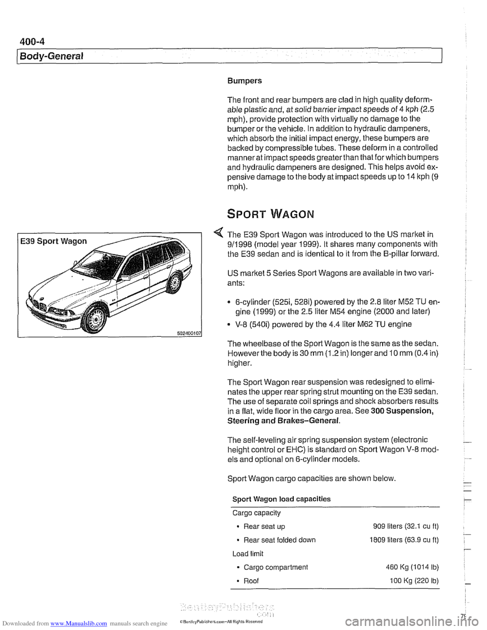
The E39 Sport Wagon was introduced to the US market in
911 998 (model year 1999). It shares many components with
the E39 sedan and is identical to it from the B-pillar forward.
US
marltet 5 Series Sport Wagons are available in two vari-
ants:
6-cylinder
(5251, 528i) powered by the 2.8 liter M52 TU en-
gine (1 999) or the 2.5 liter M54 engine (2000 and later)
* V-8 (540i) powered by the 4.4 liter M62 TU engine
The wheelbase of the Sport Wagon is the same as the sedan.
Howeverthe body is 30
mm (1.2 in) longer and 10 mm (0.4 in)
higher.
The Sport Wagon rear suspension was redesigned to elimi-
nates the upper rear spring strut mounting on the E39 sedan.
The use of separate coil springs and
shoclc absorbers results
in a flat, wide floor in the cargo area. See
300 Suspension,
Steering and Brakes-General.
The self-leveling air spring suspension system (electronic
height control or EHC) is standard on Sport Wagon V-8 mod-
els and optional on 6-cylinder models.
Sport Wagon cargo capacities are shown below.
Sport Wagon load capacities
Cargo capacity
Rear seat up 909 liters (32.1 cu ft)
Rear seat folded down I809 liters (63.9 cu ft)
Load limit
Cargo compartment
460 Kg (1014 lb)
Roof
I00 Kg (220 lb)
Page 799 of 1002
Downloaded from www.Manualslib.com manuals search engine
400-5
Body-General
Tailgate
The E39 Sporl Wagon tailgate is large with a low sill for easy
cargo loading. The tailgate opens to an angle of
88" mea-
sured from the rear roof pillar (D-pillar) and to a height of
2029
mm (79.8 in) measured from the ground to the upper edge of
the raised tailgate.
The rear window is bonded to a load bearing frame and can
be opened separately from the main tailgate. Tailgatesupport
gas springs are recessed into cavities in the roof.
Tailgate lock system
A mechanical tailgate lock cylinder is not used; the tailgate is
opened by the unlock pad above the license plate, the remote
tailgate switch located in the drivers kick panel, or via
FZV
(Iteyless entry) control.
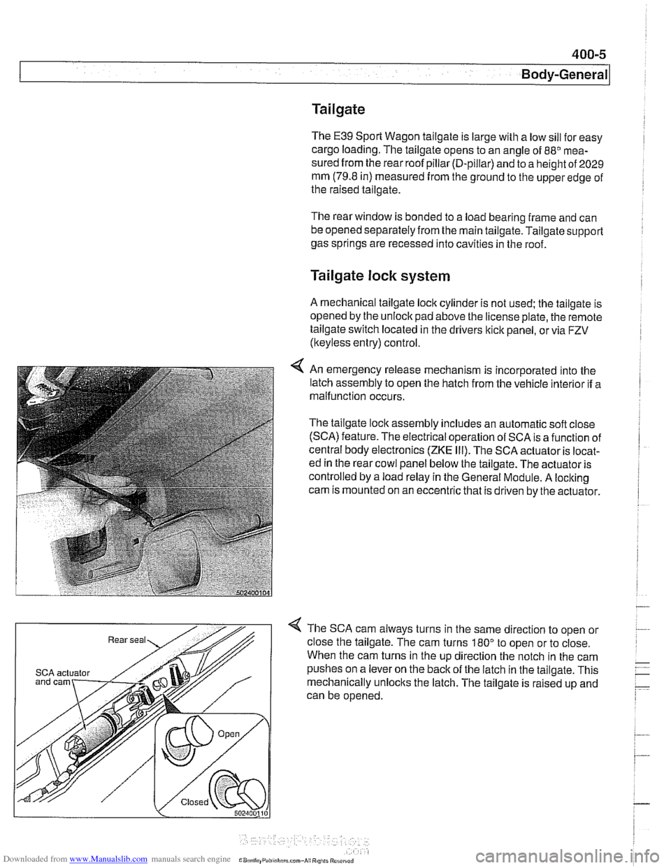
4 An emergency release mechanism is incorporated into the
latch assembly to open the hatch from the vehicle interior if a
malfunction occurs.
The tailgate lock assembly includes an automatic soft close
(SCA) feature. The electrical operation of SCA is a function of
central body electronics
(ZKE Ill). The SCA actuator is locat-
ed in the rear cowl panel below the tailgate. The actuator is
controlled by a load relay in the General Module. A locking
cam is mounted on an eccentric that is driven by the actuator.
4 The SCA cam always turns in the same direction to open or
close the tailgate. The cam turns
180" to open or to close.
When the cam turns in the up direction the notch in the cam
SCA actuator pushes on a lever on the back of the latch in the tailgate. This
mechanically unlocks the latch. The tailgate is raised up and
can be opened.
Page 834 of 1002
Downloaded from www.Manualslib.com manuals search engine
. .- -
l~runk Lid, Tailgate
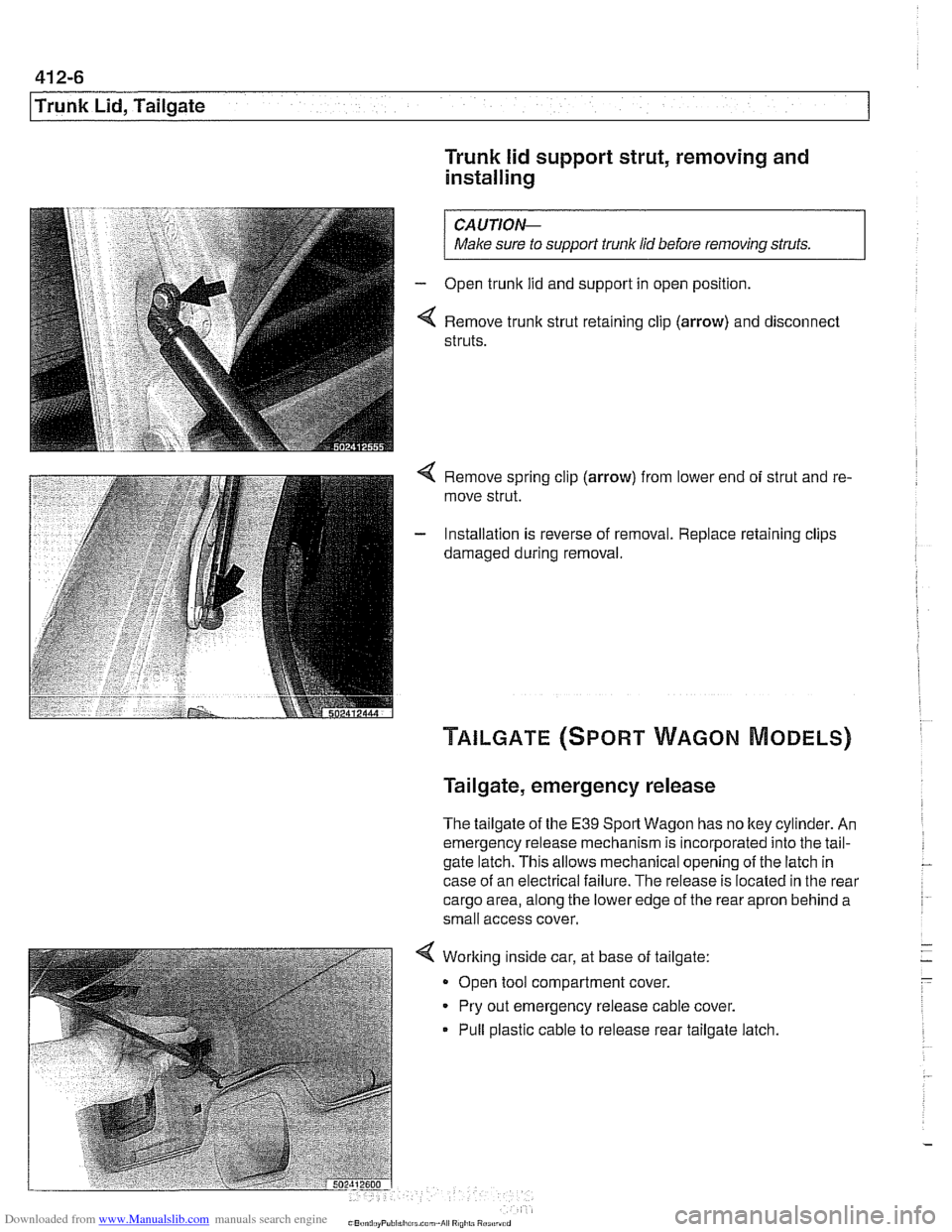
Trunk lid support strut, removing and
installing
/ Make sure to supporf trunk lid before removing struts. I
Open trunk lid and support in open position.
Remove trunk strut retaining clip
(arrow) and disconnect
struts.
4 Remove spring clip (arrow) from lower end of strut and re-
move strut.
- Installation is reverse of removal. Replace retaining clips
damaged during removal.
Tailgate, emergency release
The tailgate of the E39 Sport Wagon has no ltey cylinder. An
emergency release mechanism is incorporated into the tail-
gate latch. This allows mechanical opening of the latch in
case of an electrical failure. The release is located in the rear
cargo area, along the lower edge of the rear apron behind a
small access cover.
Working inside car, at base of tailgate:
Open tool compartment cover.
Pry out emergency release cable cover.
Pull plastic cable to release rear tailgate latch
Page 866 of 1002
Downloaded from www.Manualslib.com manuals search engine
51 2-2
I Door Windows 1
This repair group covers door glass, window regulator and
power window motor repair information.
CA U JIO&
All E39 models are equipped with side-impact airbags in the
front doors. Some models are also equipped with
airbags in
the rear doors. Be sure to read the
airbag warnings and cau-
tions in 721
Airbag System (SRS).
Electric window switch replacement is covered in 612
Switches.
The windshield, rear window, fixed rear doorglass, and cargo
compartment glass (Sport Wagon only) are bonded using
special adhesives and tools. It is recommended that bonded
glass replacement be done by an authorized
BMW service fa-
cility or an automotive glass installer.
Special tools
Some window repair operations require special tools.
Power windows
- Power window features in E39 models include:
Control of the front and rear door window motors is carried
out directly by the General Module (GM
Ill).
One-touch operation in both directions on all four windows.
Cable type window regulator used for all door windows.
. Anti-trap protection provided by pressure sensitive finger
guard.
Right front and each rear door has a single window switch
located in door handle trim.
Rear door window switches can be deactivated by press-
ing child lock-out switch in the driver's window switch block.
Convenience closinglopening of the windows from driver's
loci( cylinder or convenience opening only from remote un-
lociting feature (FZV) remote key.
Window (FZV) operation can be owner customized with
Car Memory function. See 515 Central Locking and Anti-
Theft.
After ignition is switched off, electric windows can be oper-
ated until a door is opened or until
I6 minutes has elapsed.
The GM
IiI bases window motor end position on current
draw (load). There is a maximum window motor run time of
6 seconds. The motor is then switched off even if the end
position load sensor fails.