Cylinder BMW 540i 1999 E39 Workshop Manual
[x] Cancel search | Manufacturer: BMW, Model Year: 1999, Model line: 540i, Model: BMW 540i 1999 E39Pages: 1002
Page 645 of 1002
Downloaded from www.Manualslib.com manuals search engine
31 0-9
Front Suspension
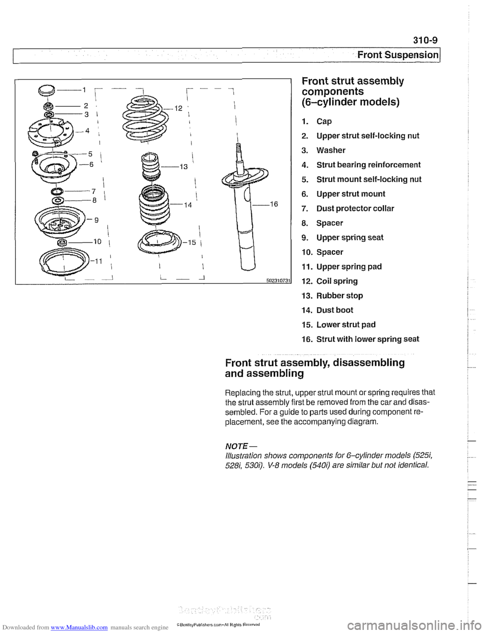
Front strut assembly
components
(6-cylinder models)
1. Cap
2. Upper strut self-locking nut
3. Washer
4. Strut bearing reinforcement
5. Strut mount self-locking nut
6. Upper strut mount
7. Dust protector collar
8. Spacer
9. Upper spring seat
10. Spacer
11. Upper spring pad
12. Coil spring
13. Rubber stop
14. Dust boot
15. Lower strut pad
16. Strut with lower spring seat
Front strut assembly, disassembling
and assembling
Replacing the strut, upper strut mount or spring requires that
the strut assembly first be removed from the car
and disas-
sembled. For a guide to parts used during component re-
placement, see the accompanying diagram.
NOTE-
Illustration shows components ior 6-cylinder models (525i,
528i, 530;). V-8 models (540i) are similar but not identical.
Page 647 of 1002
Downloaded from www.Manualslib.com manuals search engine
Front Suspension
/ Front strut top mount assembly
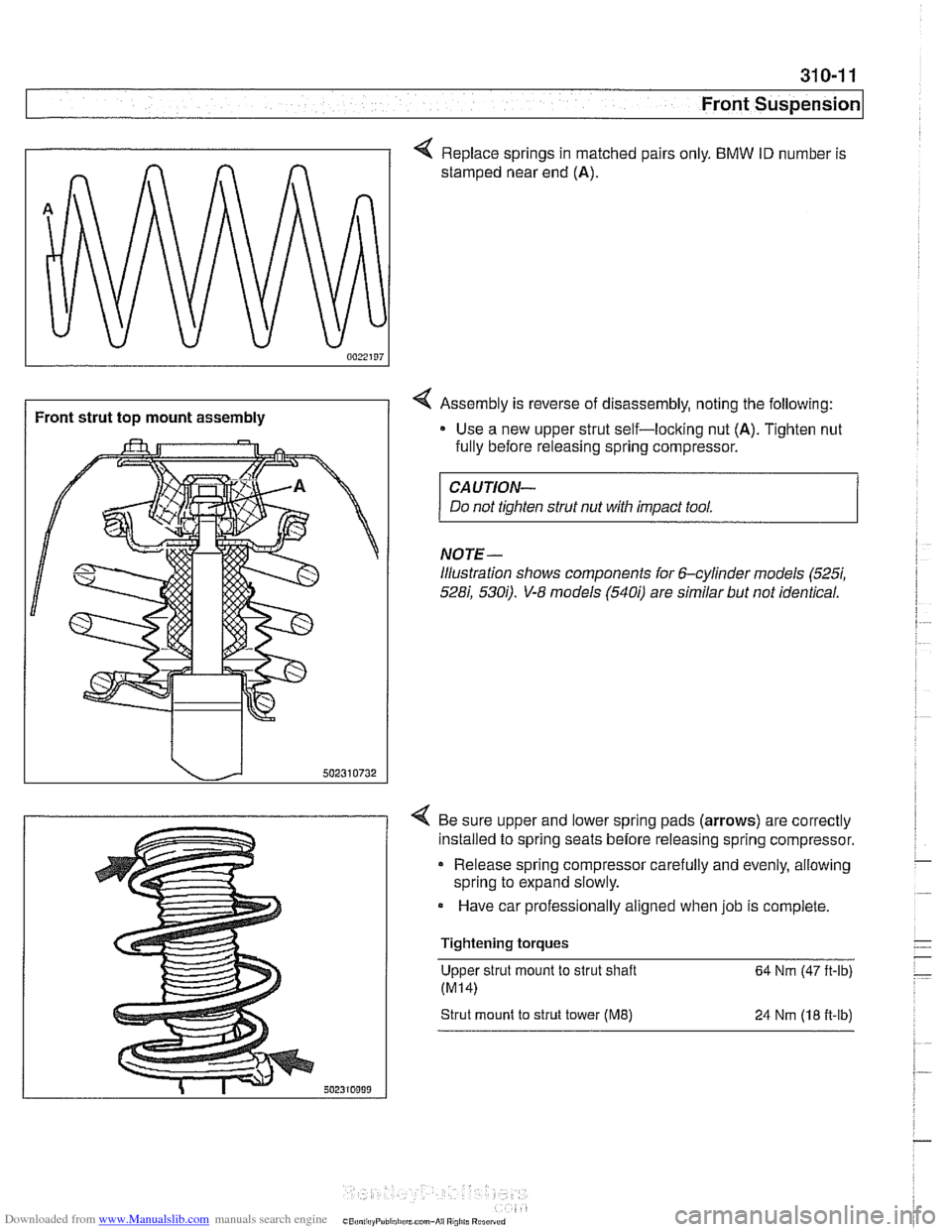
< Replace springs in matched pairs only. BMW ID number is
stamped near end
(A).
4 Assembly is reverse of disassembly, noting the following:
Use a new upper strut self-loclting nut
(A). Tighten nut
fully before releasing spring compressor.
CAUTION-
Do not tighten strut nut with impact tool.
NOTE-
illustration shows components for 6-cylinder models (5257,
528i, 5300. V-8 models (5400 are similar but not identical.
4 Be sure upper and lower spring pads (arrows) are correctly
installed to spring seats before releasing spring compressor.
Release spring compressor carefully and evenly, allowing
spring to expand slowly.
Have car professionally aligned when job is complete.
Tightening torques Upper strut mount to strut shaft
64 Nm (47 ft-lb)
Strut mount to strut tower (ME) 24 Nrn (18 fi-lb)
Page 648 of 1002
Downloaded from www.Manualslib.com manuals search engine
/~ront Susaension
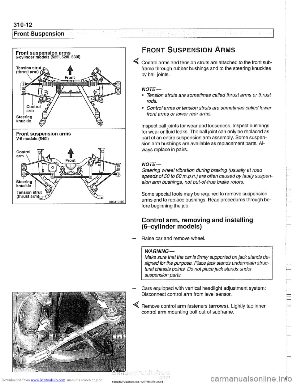
Front suspension arms FRONT SUSPENSION ARMS
Scyllnder models (5251,5281,530i)
Control arms and tension struts are attached to the front sub-
Front suspension arms V-8 models (5401)
frame through rubber bushings and to the steering ltnuckles
by ball joints.
NOTE-
Tension struts are sometimes called thrust arms or thrust
rods.
Control arms or tension struts are sometimes called lower
front arms or lower rear arms.
Inspect ball joints for wear and looseness. lnspect bushings
for wear or fluid
lealts. The ball joint can only be replaced as
part of an entire suspension arm assembly. Some suspen-
sion arm
bushinas are available as re~lacement Darts. Al-
ways replace in pairs
NOTE-
Steering wheel vibration during braking (usually at road
speeds of
50 to 60 m.p.h.) are often causedby faulty suspen-
sion arm bushings, not out-of-true brake rotors.
Some special tools may be required to remove suspension
arms and to replace bushings. Read procedures through be-
fore beginning the job.
Control arm, removing and installing
(6-cylinder models)
- Raise car and remove wheel
Male sure
that the car is firmly supported on jack stands de-
signed for the purpose. Place jack stands underneath struc-
tural chassis points. Do not place jack stands under
suspension
parfs.
Cars equipped with vertical headlight adjustment system:
Disconnect control arm from level sensor.
Remove control arm fasteners (arrows). Lightly tap inner
control arm mounting bolt out of subframe.
Page 652 of 1002
Downloaded from www.Manualslib.com manuals search engine
I Front Suspension
Tension strut, removing
and installing
- Raise car and remove wheel.
WARNING-
Make sure that the car is firmly supported on jack stands de-
signed for the purpose. Place jack stands underneath struc-
tural chassis points. Do not place
jack stands under
suspension parts.
- Remove engine splash shield
6-cylinder models: Remove
brake cooling duct.
V-8 models: Detach stabilizer bar from front subframe.
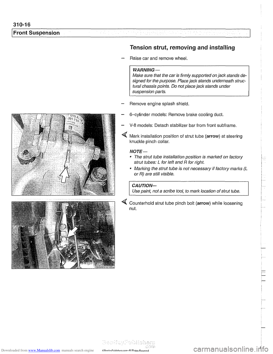
Mark installation position of strut tube (arrow) at steering
ltnuckle pinch collar.
NOJE-
* The strut tube installation position is marlted on factory
strut tubes:
L for left and R for right.
* Marlting the strut tube is not necessary if factory marks (L
or R) are still visible.
CAUJION-
Use paint, not a scribe tool, to mark location of strut tube. 1
4 Counterhold strut tube pinch bolt (arrow) while loosening
nut.
Page 655 of 1002
Downloaded from www.Manualslib.com manuals search engine
Front Suspension
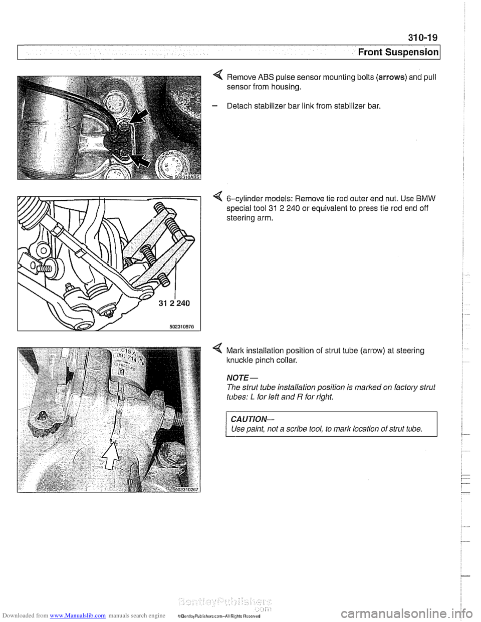
4 Remove ABS pulse sensor mounting bolts (arrows) and pull
sensor from housing.
- Detach stabilizer bar link from stabilizer bar.
4 6-cylinder models: Remove tie rod outer end nut. Use BMW
special tool
31 2 240 or equivalent to press tie rod end off
steering arm.
4 Mark installalion position of strut tube (arrow) at steering
knuckle pinch collar.
NOTE-
The strut tube installation position is marked on factory strut
tubes:
L for left and R for right.
CAUTION-
Use paint, not a scribe tool, to mark location of strut tube.
Page 659 of 1002
Downloaded from www.Manualslib.com manuals search engine
1 320 Steering and Wheel Alignment
General ........................... .32 0.2
Special tools
........................ .32 0.2
Steering system
..................... .32 0.4
Steering system variations
............. .32 0.5
Steering system warnings and cautions
... .32 0.6
Steering Wheel .................... .32 0.7
Steering wheel. removal and installation
.. .32 0.7
Steering Column ................. .32 0.1 0
Steering column components .......... .32 0.10
Steering column trim, removing
and replacing
...................... .32 0.10
lgnition switch ring antenna (EWS).
removing and installing
............... .32 0.1 1
lgnition lock cylinder.
removing and installing
............... .32 0-1 1
Steering column lock. removing
and installing
....................... .32 0.12
lgnition
interloclc cable. removing and installing
(models with automatic transmission)
... .32 0.13
Interlock cable. adjusting
(models with automatic transmission)
... .32 0.14
Steering column. removing and installing
. .32 0.14
Steering column adjustment motors.
removing and installing
............... .32 0.16
Power Steering Pump ............. .32 0.17
Power steering pump. removing
and installing
....................... .32 0.1 7
Power steering system.
bleeding and filling
.................. .32 0.18
Rack and Pinion Steering
(6-cylinder models)
............... 320-19
Rack and pinion steering components
(6-cylinder models)
.................. 320-1 9
Steering rack. removing and installing
.... 320-19
Steering
rack boot. replacing ........... 320-22
Tie rod (outer). replacing
.............. 320-22
Tie rod (inner). replacing
.............. 320-23
Steering Gearbox (V-8 models) .... 320-24
Steering gearbox system components
. .
(V-8 models) ....................... 320-24
Steering gearbox, removing and installing 320-25
Pitman arm. removing and installing ..... 320-28
Pitman arm. adjusting ................ 320-29
Steering idler arm. removing
and installing
....................... 320-30
Idler arm bushing. replacing ........... 320-31
Center tie rod. replacing
.............. 320-32
Wheel Alignment .................. 320-33
Camber
........................... 320-33
Caster
............................ 320-33
Front toe and toe difference angle
....... 320-34
Reartoe ........................... 320-34
Preparing for alignment
............... 320-35
Alignment specifications tables
......... 320-35
Page 660 of 1002
Downloaded from www.Manualslib.com manuals search engine
I Steering and Wheel Alignment
This repair group covers steering wheel and column removal
and steering system service, including wheel alignment infor-
mation.
NOTE-
Ignition loclc cylinder replacement is covered in this sec-
tion.
a For information on steering column mounted switches, in-
cluding the ignition switch, see
612 Switches.
Special tools
Some special tools are necessary to carry out the repairs and
adjustments required for steering service and wheel align-
ment. Be sure to read the procedures through before starting
work on the vehicle.
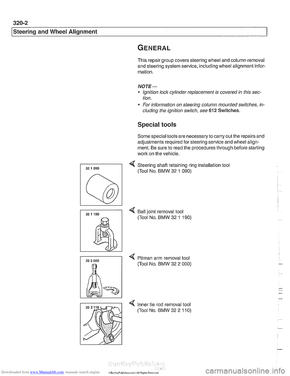
4 Steering shafl retaining ring installation tool
(Tool No. BMW 32
1 090)
4 Bail joint removal tool
(Tool No. BMW 32
1 190)
4 Pitman arm removal tool
(Tool No. BMW 32 2
000)
4 Inner tie rod removal tool
(Tool No. BMW 32 2
110)
Page 662 of 1002
Downloaded from www.Manualslib.com manuals search engine
I Steerina and Wheel Alianment
Steering
system
Two types of steering gear are used in the E39 series models.
6-cylinder
(5251, 528i and 530i) models are equipped with
rack and pinion steering. The steering rack is mounted to
an aluminum subframe.
V-8
(540i) models are equipped with a recirculating ball
and nut steering gearbox mounted to a steel subframe.
At low speeds, maximum power assist is provided to ease
parking and city driving. At high speeds, assist is reduced to
ensure stability. The power steering system varies assist
based on engine speed.
Power boost for the steering is provided by an engine-driven
hydraulic pump. A hydraulic control valve is used to control
boost pressure.
The steering wheel connects to the steering gear via an ad-
justable steering column which incorporates a rubber cou-
pling ("guibo") to dampen vibration and noise.
Power steering fluid is supplied from the fluid
reservoir to the
pump and to the steering gear via rubberlmetal hoses.
The return line from the steering gear to the
reservoir loops
into the airstream in front of the radiator and connects to the
steering fluid cooler. The fluid cooler is attached to a cassette
which also includes cooling coils for engine oil, transmission
fluid and AIC condenser.
The steering gear requires no maintenance other than align-
ment and periodic inspection for worn components. Inspect
rubber rack boots
(rack and pinion system) and tie-rod end
boots periodically for tears or damage. Replace
if necessary.
-
NOTE-
The airbag system is traditionally referred to as Supplemen-
tal Restraint System (SRS). The
BMW versfon of SRS used
m the E39 models is known as the Multiple Restraint System - (MRS). - -
Page 669 of 1002
Downloaded from www.Manualslib.com manuals search engine
Steering and Wheel ~li~nrnentl
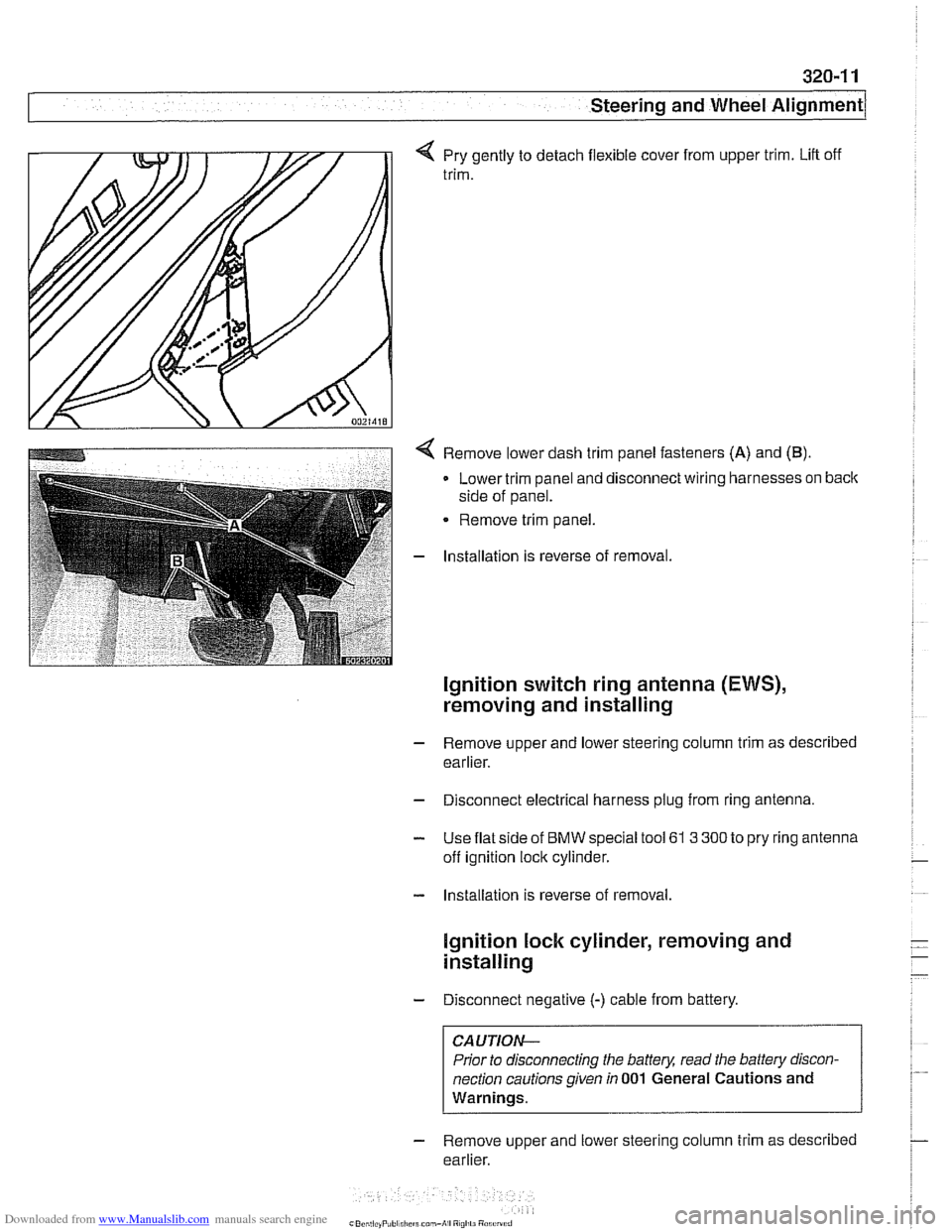
q Pry gently to detach flexible cover from upper trim. Lift off
trim.
< Remove lower dash trim panel fasteners (A) and (B).
Lower trim panel and disconnect wiring harnesses on back
side of panel.
Remove trim panel.
- Installation is reverse of removal.
Ignition switch ring antenna (EWS),
removing and installing
- Remove upper and lower steering column trim as described
earlier.
- Disconnect electrical harness plug from ring antenna.
- Use flat side of BMW special tool 61 3 300 to pry ring antenna
off ignition lock cylinder.
- Installation is reverse of removal.
lgnition lock cylinder, removing and
installing
- Disconnect negative (-) cable from battery.
CAUTION-
Prior to disconnecting the battery, read the battery discon-
nection cautions given
in 001 General Cautions and
Warnings.
- Remove upper and lower steering column trim as described
earlier.
Page 670 of 1002
Downloaded from www.Manualslib.com manuals search engine
I Steering and Wheel Alignment
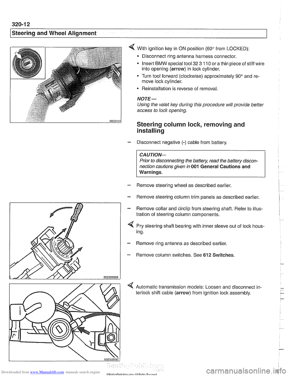
With ignition key in ON position (60" from LOCKED):
- Disconnect ring antenna harness connector.
Insert
BMW special tool 32 3 110 or a thin piece of stiff wire
into opening (arrow) in lock cylinder.
Turn tool forward (clockwise) approximately 90" and re-
move lock cylinder.
* Reinstallation is reverse of removal.
NOTE-
Using the valet ley during this procedure will provide better
access to lock opening.
Steering column lock, removing and
installing
- Disconnect negative (-) cable from battery.
CAUTIO&
Prior to disconnecting the battery, read the battery discon-
nection cautions given
in 001 General Cautions and
Warnings.
- Remove steering wheel as described earlier.
- Remove steering column trim panels as described earlier.
- Remove collar and circlip from steering shaft. Refer to illus-
tration of steering column components.
4 Pry steering shaft bearing with inner sleeve out of lock hous-
ing.
- Remove ring antenna as described earlier.
- Remove column switches. See 612 Switches.
< Automatic transmission models: Loosen and disconnect in-
terloclc shift cable (arrow) from ignition lock assembly.