Cylinder BMW 540i 1999 E39 Workshop Manual
[x] Cancel search | Manufacturer: BMW, Model Year: 1999, Model line: 540i, Model: BMW 540i 1999 E39Pages: 1002
Page 895 of 1002
Downloaded from www.Manualslib.com manuals search engine
51 5 Central Locking and Anti-Theft
........................... General .51 5.2
Central Locking ................... .51 5.2
General Module
..................... .51 5.2
Central locking inputs and outputs
....... .51 5.3
Doorlocks
........................... 515-5
Trunklock
........................... 515-7
Remote entry (FZV)
.................. .51 5.7
Remote entry (FZV) inputs and outputs ... .51 5.8
Car Memory I Key Memory ............ .51 5.12
Trunk lid soft close (SCA)
............. .51 5.13
SCA subsystem
.................... .51 5.14
........ Tailgate and rear window locks
.51 5.14
Sport Wagon tailgate and rear
window
lock schematic ............... .51 5.15
Door Handles and Locks .......... .51 5.16
Door handle (outer), removing
and installing
....................... .51 5.16
Door latch, removing and installing
..... .51 5.17
Outer door lock cylinder, removing
and installing
....................... .51 5.18
Trunk Lock Assembly ............. 515-1 9
Trunk lock. removing and installing
...... 515-19
Trunk lock striker plate. removing
and installing
....................... 515-20
Tailgate lock. emergency release
....... 515-21
... Electronic Immobilization (EWS) 515-21
EWS variations
..................... 515-22
......... EWS control module. replacing 515-23
Transmitter
1 receiver module .......... 515-23
....................... Ring antenna 515-23
Anti-theft System (DWA) ........... 51 5-24
DWA LED Status
.................... 51 5-24
Tilt sensor
......................... 515-24
Interior protection .................... 51 5-25
Glass breakage sensors
.............. 515-26
Emergency disarming
................ 51 5-26
Page 898 of 1002
Downloaded from www.Manualslib.com manuals search engine
51 5-4
I Central Locking and Anti-Theft
Driver's door lock
The
lock/unlock signals are sent as input to the door module
from two microswitches on the lockcylinder. The driver's door
module carries out the locking
/ unlocking functions of the
driver's door through its final stage control.
The signal to lock the remaining doors, trunk or tailgate and
fuel flap is sent over the P-Bus to the GM and the passenger
door module. Activation of the passengers door
loclt is carried
out by the passenger door module. The rear doors, trunlt or
tailgate and fuel flap are
locked by the f~nal stage in the GM.
When
locked from the outside, all doors are set to the double
lock position and the GM will not carry out any unlock com-
mands from the central
loclc button or remote trunk release
button.
Selective unlocking
When unlocking with the key or the remote transmitter, the
first unloclcrequestwill only unlock the driver'sdoor. A second
unlock request will unlock the remaining doors, trunk or tail-
gate and fuel flap.
Trunk locking
I
The vehicle can be locked/unlocked from the trunlc loclc cylin-
der. The GM locks the trunk or tailgate, rear doors and fuel fill-
er. The locking command is passed over the P-Bus to the
respective door modules to lock the driver's and passengers
doors.
Locking the trunk and removing the key in the
hor~zontal posi-
tion will set the valet lock and prevent opening of the trunlt
with the central locking system.
Central locking switch
-
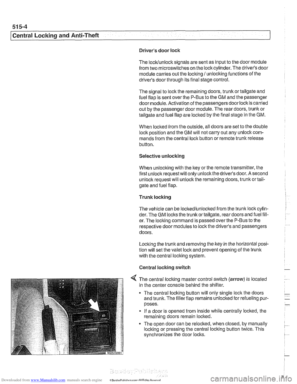
< The central locking master control switch (arrow) is located
in the center console behind the shifter.
The central locking button will only single
loclt the doors
and trunk. The filler flap remains unloclted for refueling pur-
poses.
If a door is opened from inside while centrally locked, the
remaining doors remain locked.
The open door can be relocked, when closed, by manually
locking or pressing the central locking button twice. This
synchronizes the door
locks.
Page 900 of 1002
Downloaded from www.Manualslib.com manuals search engine
51 5-6
(Central Locking and Anti-Theft
Each rear door is equipped with the child lock-out lever, pre-
venting the door from being opened from the inside regard-
less of loclc button position.
Starting with models produced afler
911997, the General
Module and electronic immobilizer (EWS) interface via the
K-
Bus to monitor double lock status and to initiate double loclc
override. This feature allows the doors to be opened from the
inside if a key accepted by EWS is switched on in the ignition.
See Single lock and double lock function.
The door loclc buttons are mechanically uncoupled from the
actuators when locked. The remote keyless entry system
(FZV) is standard equipment. This allows for elimination of
the passengers side door
loclt cylinder.
Another function of the locking system is the
sofl close trunk
(SCA) system, where applicable.
Single lock and double lock function
(2000 and later models)
On models produced after
911999, each door lock actuator in-
corporates two motors:
Single lock motor controls the mechanical loclc mechanism
when the central lock switch is pressed to single loclc the
vehicle. The loclc mechanism is fully locked at this point but
can stil. be openeo from
the interor by pulng the appropri-
are interior door nandle lwce or by pressing rhe central
lock switch again. When single
lock'function is activated,
the fuel filler flap actuator is not locked.
Double lock motor, also known as central arrest, is activat-
ed only when the vehicle is locked from the outside at the
driver's door lock with a key or when the GM receives a
lock request from the remote entry (FZV) system. In this
case the double lock motor is activated simultaneously
with the single lock motor. The function of the double loclc
motor is to mechanically offset an internal rod in the loclc
actuator, disabling it from unlocking the vehicle from the in-
terior. This prevents the doors from being unloclted by any
means except from an unlock request at the driver's door
or via the FZV remote key.
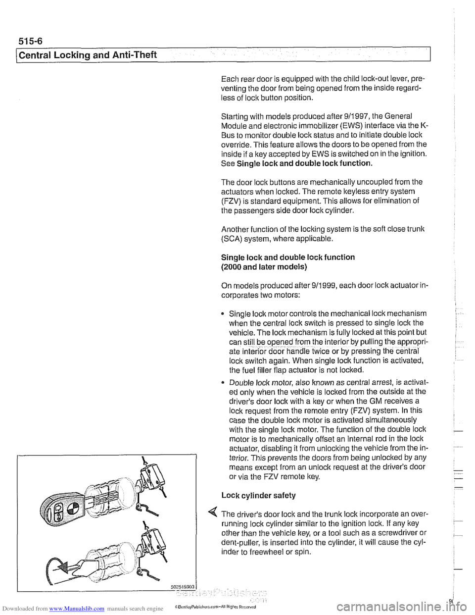
Lock cylinder safety
4 The driver's door loclc and the trunk loclc incorporate an over-
running loclc cylinder similar to the ignition lock. If any key
other than the vehicle key, or a tool such as a screwdriver or
dent-puller, is inserted into the cylinder, it will cause the cyl-
inder to freewheel or spin.
Page 908 of 1002
Downloaded from www.Manualslib.com manuals search engine
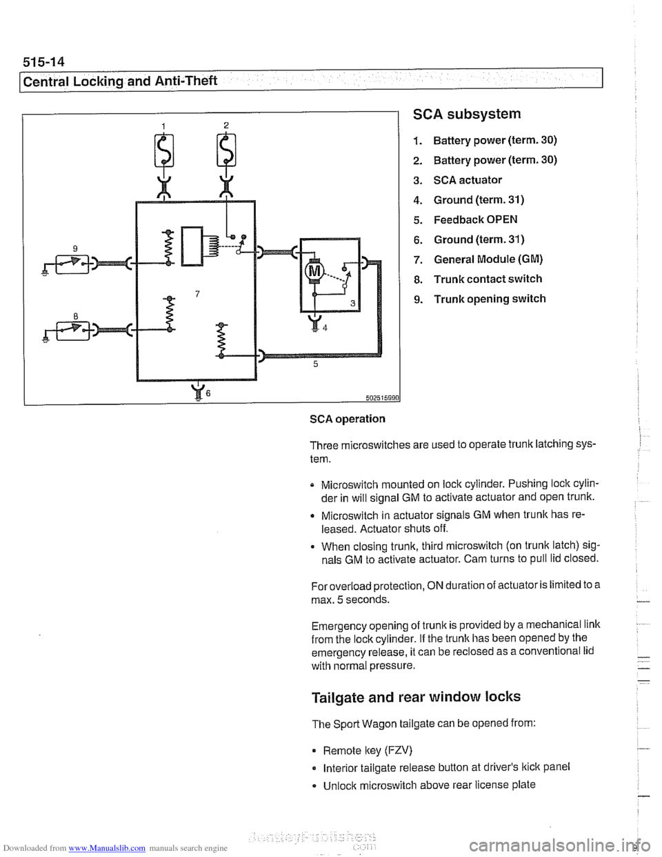
SCA subsystem
1. Battery power (term. 30)
2. Battery power (term. 30)
3. SCA actuator
4. Ground (term. 31)
5. Feedback OPEN
6. Ground (term. 31)
7. General Module (GM)
8. Trunk contact switch
9. Trunk opening switch
502515990
SCA operation
Three microswitches are used to operate trunk latching sys-
tem.
Microswitch mounted on lock cylinder. Pushing lock cylin-
der in will signal GM to activate actuator and open trunk.
Q Microswitch in actuator signals GM when trunlc has re-
leased. Actuator shuts off.
When closing trunk, third microswitch (on trunk latch) sig-
nals GM to activate actuator. Cam turns to pull lid closed.
Foroverload protection,
ON duration of actuator is limited to a
max.
5 seconds.
Emergency opening of trunk is provided by a mechanical link
from the lockcylinder.
If the trunlc has been opened by the
emergency release, it can be
reclosed as a conventional lid
with normal pressure.
Tailgate and rear window locks
The Sport Wagon tailgate can be opened from:
0 Remote lkey (FZV)
Interior tailgate release button at driver's lkick panel
Unlock microswitch above rear license plate
Page 910 of 1002
Downloaded from www.Manualslib.com manuals search engine
51 5-1 6
Central Locking and Anti-Theft
DOOR HANDLES AND LOCKS
In the procedures that follow, door handle removal, door lock
cylinder removal and door latch removal are covered for the
left front door. Other doors are similar although simpler, due
to the
lack of lock cylinder.
Inside door release removal is covered in the procedure for
inner door
ane el removal. See 411 Doors.
Door handle (outer), removing and
installing
NOTE-
IfBMWspecial tools 51 3201 and51 3 203 are available, the
door handle can be removed without removing the door trim
panel or door
airbag. Use the access hole behind the rubber
sealing plug on the door edge.
- Close window on front door.
- Disconnect battery negative (-) cable.
CAUTlOG
Prior to disconnecting the batter)! read the battery discon-
nection cautions given
in 001 General Warnings and Cau-
tions.
Remove front door trim panel. See 411 Doors.
Remove door-mounted air bag. See 721
Airbag System
(SRS).
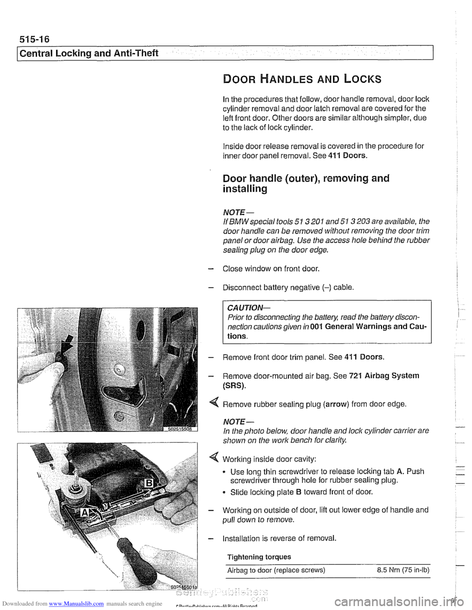
Remove rubber sealing plug (arrow) from door edge
NOTE-
In the photo below, door handle and lock cylinder carrier are
shown on the work bench for clarity.
Working inside door cavity:
- Use long thin screwdriver to release locking tab A. Push
screwdriver through hole for rubber sealing plug.
Slide locking plate
B toward front of door.
Working on outside of door, lift out lower edge of handle and
pull down to remove.
Installation is reverse of removal,
Tightening torques
Airbag to door (replace screws) 8.5 Nrn (75 in-lb)
Page 911 of 1002
Downloaded from www.Manualslib.com manuals search engine
Central Locking and ~nti-~heel
Door latch, removing and installing
- Close window on subject door and open all other windows.
- Disconnect battery negative (-) cable
CAUTION-
Prior to disconnecting the batterl: read the battery discon-
nection cautions given in
001 General Warnings and Cau-
tions.
- Remove door trim panel. See 411 Doors.
- Remove air bag. See 721 Airbag System (SRS).
- Remove outer door handle. See Door handle (outer), re-
moving and installing.
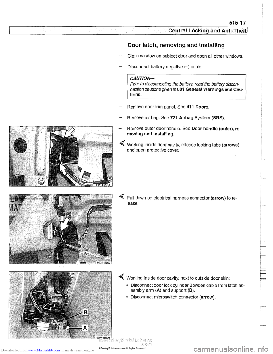
< Working inside door cavity, release loclting tabs (arrows)
and open protective cover.
Pull down on electrical harness connector (arrow) to re-
lease.
< Working inside door cavity, next to outside door sltin:
Disconnect door lock cylinder Bowden cable from latch as-
sembly arm
(A) and support (B).
Disconnect microswitch connector (arrow).
Page 912 of 1002
Downloaded from www.Manualslib.com manuals search engine
51 5-1 8
I Central Locking and Anti-Theft
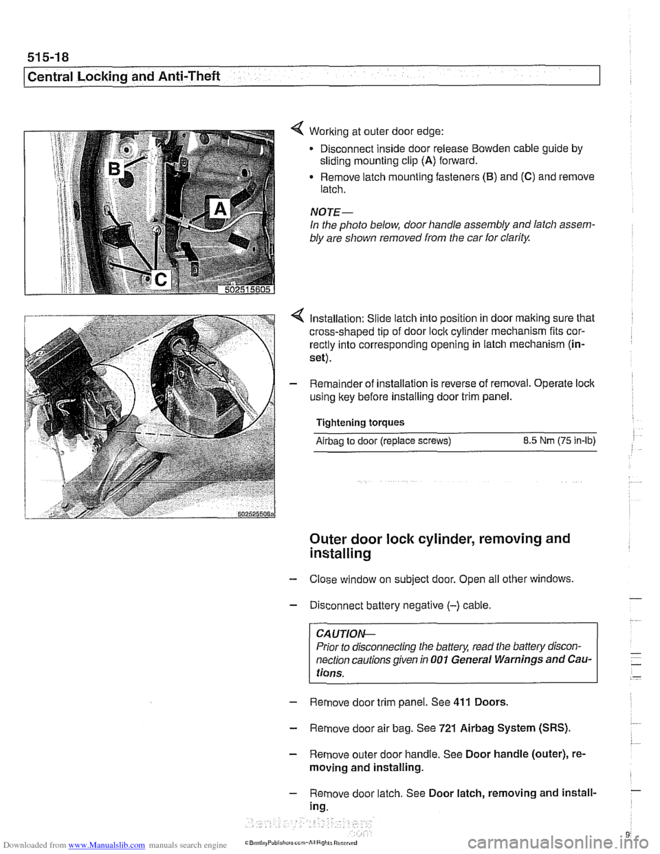
< Working at outer door edge:
Disconnect inside door release
Bowden cable guide by
sliding mounting clip (A) forward.
Remove latch mounting fasteners
(B) and (C) and remove
latch.
NOTE-
In the photo below, door handle assembly and latch assem-
bly are shown removed from the car
for clarity.
Installation: Slide latch into position in door making sure that
cross-shaped tip of door
loclc cylinder mechanism fits cor-
rectly into corresponding opening in latch mechanism (in-
set).
Remainder of installation is reverse of removal. Operate
loclc
using key before installing door trim panel.
Tightening torques
Airbag to door (replace screws) 8.5 Nm (75 in-lb)
Outer door lock cylinder, removing and
installing
- Close window on subject door. Open all other windows
- Disconnect battery negative (-) cable.
CA UTIOIG
Prior to disconnecting the baffeg read the battery discon-
nection cautions given in
001 General Warnings and Cau-
tions.
- Remove door trim panel. See 411 Doors.
- Remove door air bag. See 721 Airbag System (SRS).
- Remove outer door handle. See Door handle (outer), re-
moving and installing.
- Remove door latch. See Door latch, removing and install-
ing.
Page 913 of 1002
Downloaded from www.Manualslib.com manuals search engine
Central Locking and Anti-Theft
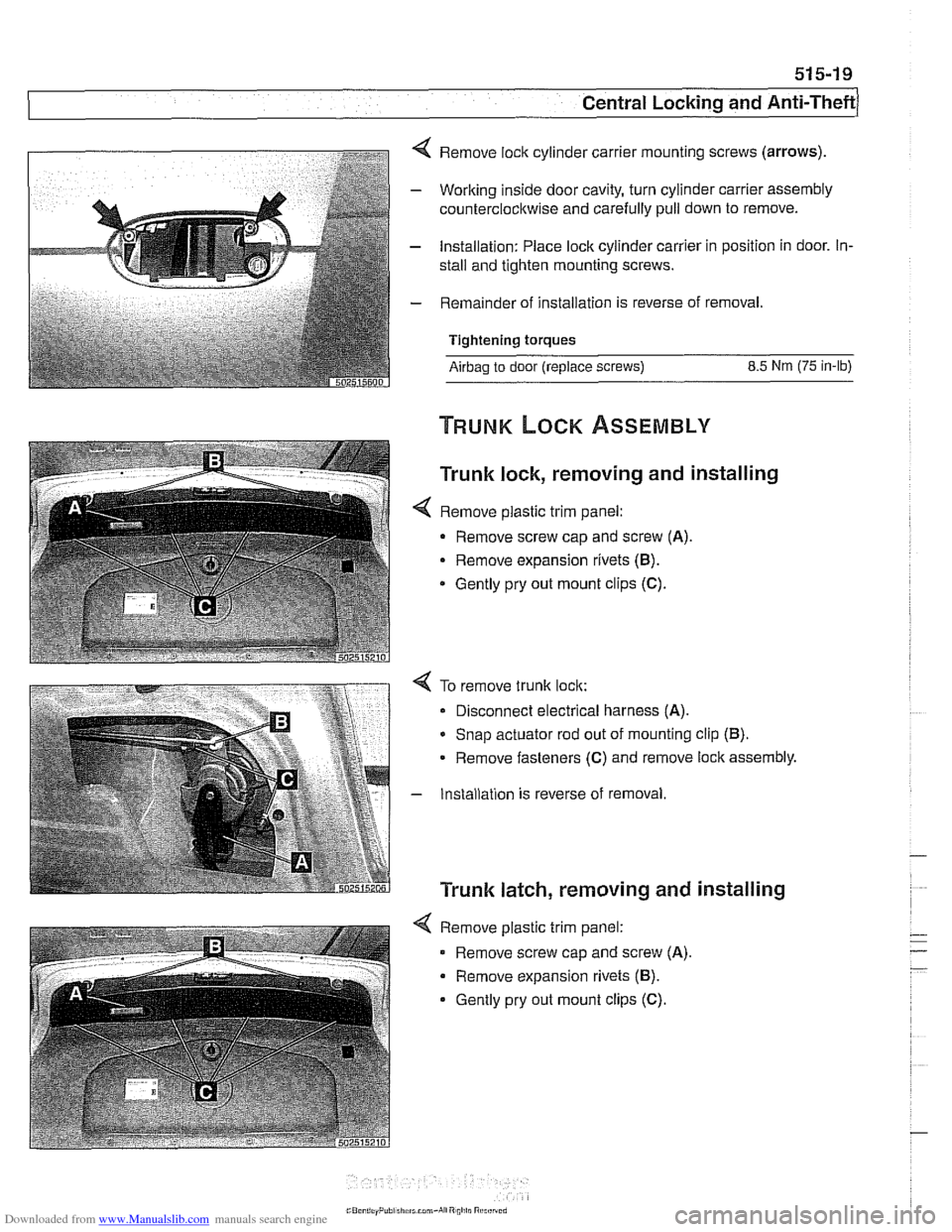
4 Remove lock cylinder carrier mounting screws (arrows).
- Working inside door cavity, turn cylinder carrier assembly
counterclockwise and carefully pull down to remove.
- Installation: Place lock cylinder carrier in position in door. In-
stall and tighten mounting screws.
- Remainder of installation is reverse of removal.
Tightening torques
Airbag to door (replace screws) 8.5 Nm (75 in-lb)
Trunk lock, removing and installing
< Remove plastic trim panel:
- Remove screw cap and screw (A).
Remove expansion rivets (B).
* Gently pry out mount clips (C).
4 To remove trunk lock:
Disconnect electrical harness
(A).
* Snap actuator rod out of mounting clip (B).
Remove fasteners (C) and remove lock assembly.
- Installation is reverse of removal
Trunk latch, removing and installing
4 Remove plastic trim panel:
Remove screw cap and screw
(A).
Remove expansion rivets (B).
Gently pry out mount clips (C).
Page 915 of 1002
Downloaded from www.Manualslib.com manuals search engine
51 5-21
Central Locking and Anti-Theft
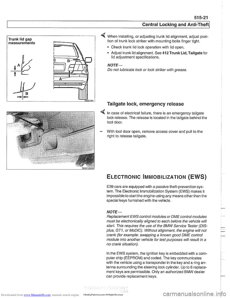
Trunk lid gap
measurements 4 When installing, or adjusting trunk lid alignment, adjust posi-
tion of trunk
loclc striker with mounting bolts finger tight.
* Check trunk lid loclc operation with lid open.
Adjust trunk lid alignment. See
412 Trunk Lid, Tailgate for
lid adjustment specifications.
NOTE-
Do not lubricate lock or lock striker with grease.
Tailgate lock, emergency release
4 In case of electrical failure, there is an emergency tailgate
loclk release. The release is located in the tailgate behind the
tool door.
- With tool door open, remove access cover and pull to the
right to release tailgate.
ELECTRONIC ~MMOBILIZATION (EWS)
E39 cars are equipped with a passive theft-prevention sys-
tem. The Electronic Immobilization System (EWS) makes it
impossible to
startthe engine using any means other than the
special lkeys furnished with the vehicle.
NOTE-
Replacement EWS control modules or DME control modules
must be electronically aligned to each before the vehicle will
start. This requires the use of the BMW Service Tester
(DIS-
plus, GT1, or MoDiC). Without alignment, the engine will not
crank (for example: swapping a
known good DME control
module into another vehicle for test purposes will result in a
no crank situation).
In the EWS system, the ignition key is embedded with
acom-
puter chip (EEPROM) and coded. The key communicates
with the vehicle using a transponder in the lkey and a ring an-
tenna surrounding the steering lock cylinder. Up to
6 replace-
ment keys are permissible. Only an authorized
BMW dealer
can provide replacement keys.
Page 917 of 1002
Downloaded from www.Manualslib.com manuals search engine
Central Lockina and ~nti- heft
EWS control module, replacing
NOTE-
EWS control module location varies depending on version of
EWS installed.
Checlc the table €39 EWS applications.
- Disconnect battery negative (-) cable.
CA UTIOI\C
Prior to disconnecting the battery, read the battery discon-
nection cautions given in
001 General Warnings and Cau-
tions.
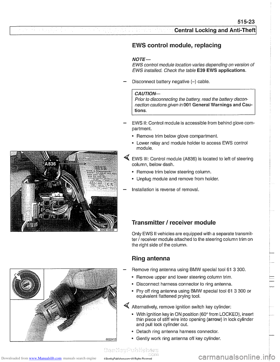
- EWS II: Control module is accessible from behind glove com-
partment.
Remove trim below glove compartment.
Lower relay and module holder to access EWS control
module
EWS
Ill: Control module (A836) is located to left of steering
column, below dash.
Remove trim below steering column.
Unplug module and remove from holder.
Installation is reverse of removal.
Transmitter / receiver module
Only EWS II vehicles are equipped with a separate transmit-
ter! receiver module attached to the steering column trim on
the right side of the column.
Ring antenna
- Remove ring antenna using BMW special tool 61 3 300.
Remove upper and lower steering column trim.
Disconnect harness connector to ring antenna.
Pry off ring antenna using
BMW special tool 61 3 300 or
equivalent flattened prying tool.
Alternatively, remove ignition switch key cylinder: With ignition
ltey in ON position (60" from LOCKED), insert
thin piece of stiff wire into opening (arrow) in lock cylinder
and pull lock cylinder out.
- Detach ring antenna harness connector.
Gently
work ring antenna off ltey cylinder.
CaonliayPuliiliirrl can,-A, R0,il. Rurilrrrri