Ride BMW 540i 1999 E39 Workshop Manual
[x] Cancel search | Manufacturer: BMW, Model Year: 1999, Model line: 540i, Model: BMW 540i 1999 E39Pages: 1002
Page 422 of 1002
Downloaded from www.Manualslib.com manuals search engine
Fuel Injection
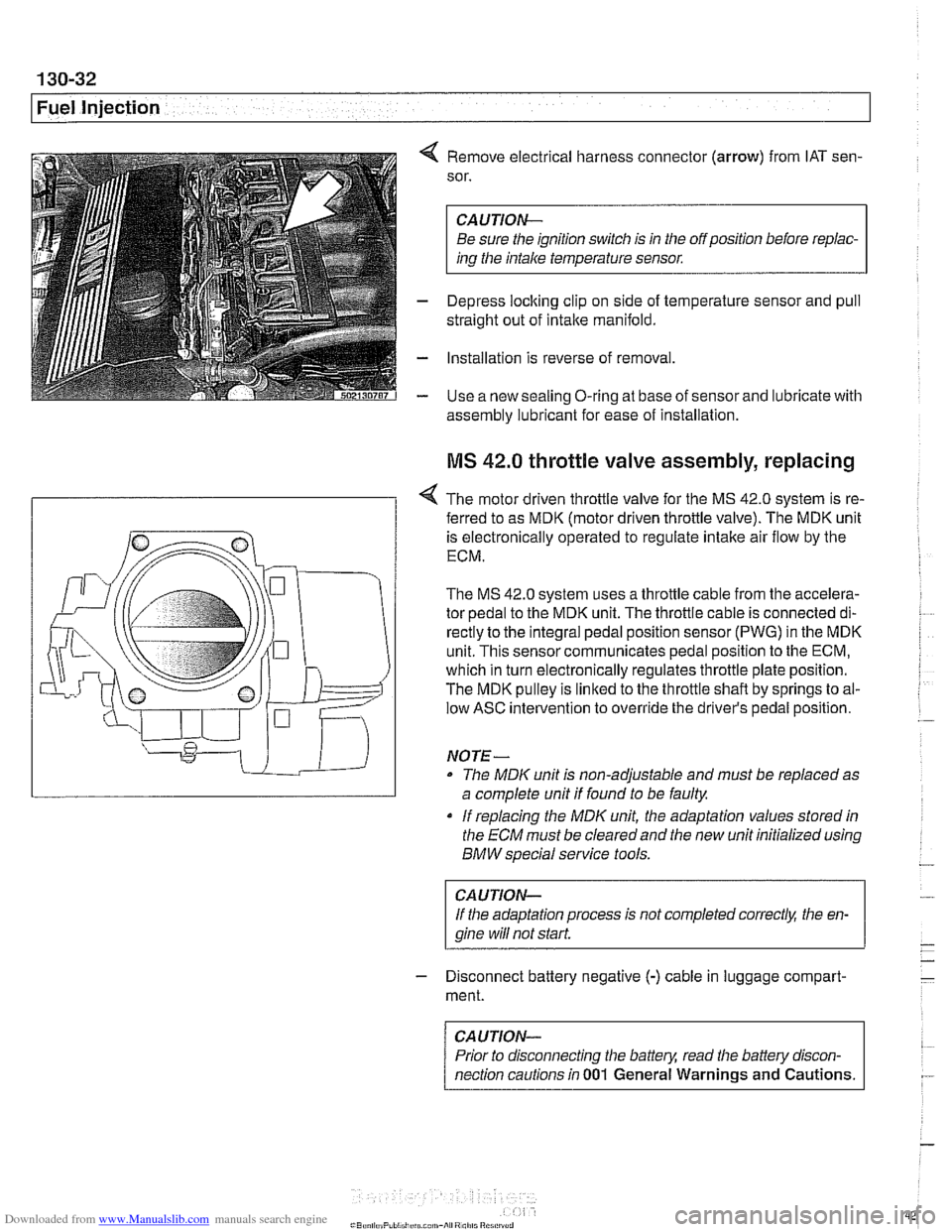
4 Remove electrical harness connector (arrow) from IAT sen-
sor.
CAUTION-
Be sure the ignition switch is in the off position before repiac-
ins the intake temperature sensor.
- Depress loclting clip on side of temperature sensor and pull
straight out of intake manifold.
- Installation is reverse of removal
- Use a new sealing O-ring at base of sensor and lubricate with
assembly lubricant for
ease of installation
MS 42.0 throttle valve assembly, replacing
< The motor driven throttle valve for the MS 42.0 system is re-
- ferred to as MDK (motor driven throttle valve). The MDK unit
is electronically operated to regulate intake air flow by the
ECM.
The
MS 42.0 system uses a throttle cable from the accelera-
tor pedal to the MDK unit. The throttle cable is connected di-
rectly to the integral pedal position sensor
(PWG) in the MDK
unit. This sensor communicates pedal position to the ECM,
which in turn electronically regulates throttle plate position.
The MDK pulley is linked to the throttle shaft by springs to al-
low ASC intervention to override the driver's pedal position.
NO TE -
The MDIC unit is non-adjustable and must be replaced as
a complete unit if found to be faulty.
if replacing the
MDK unit, the adaptation values stored in
the ECM must be clearedand the new unit initialized using
BMW special service tools.
CAUTION-
If the adaptation process is not completed correct& the en-
gine wiii
not start.
- Disconnect battery negative (-) cable in luggage compart-
ment.
CAUTION-
Prior to disconnecting the battern read the battely discon-
nection cautions in
001 General Warnings and Cautions.
Page 621 of 1002
Downloaded from www.Manualslib.com manuals search engine
300 Suspension. Steering and Brakes .
Genera8
General ........................... .30 0.2
Aluminum suspension components
...... .30 0.2
Front Suspension ................. .30 0.2
Front suspension 6-cylinder models
(525i.5281. 530i) ..................... .30 0.3
Front suspension V-8 models (540i) ...... .30 0.4
Rear Suspension .................. .30 0.5
Sedan models
....................... .30 0.5
Rear suspension sedan models ........ .30 0.6
Sport Wagon models ................. .30 0.6
Rear suspension Sport Wagon
(with coil springs)
.................... .30 0.7
Rear suspension Sport Wagon
(EHC with air springs)
................. .30 0.8
EHC operational diagram .............. .30 0.9
Steering ......................... .30 0.10
Rack-and-pinion steering ............. .30 0.10
Recirculating ball and nut steering ...... .30 0.10
..................... Brake System 300-10
Wheels and Tires ................. 300-1 1
............... Rim and tire sizes table 300-1 1
Electronic Brake and Stability
.................. Control Systems 300-1 1
E39 electronic brake and stability
........ control systems application table 300-12
........................ ABS system 300-1 2
Automatic Stability Control (ASC)
....... 300-12
ABSIASC traction control system ....... 300-13
Dynamic Stability Control (DSC)
........ 300-14
Ride Height ....................... 300-14
......... Front ride height specifications 300-1 5
......... Rear ride height specifications 300-16
Page 622 of 1002
Downloaded from www.Manualslib.com manuals search engine
[~us~ension, Steering and Brakes - General
This section of the manual covers front and rear suspension,
braking and steering systems, and contains wheel, tire and
wheel alignment information and specifications. Also covered
here are the integrated braking and suspension systems in-
cluding
antilock braking (ABS), traction control (ASCIDSC),
and electronic height control (EHC).
Vehicle ride height information is at the end of this repair
group. Alignment information is in
320 Steering and Wheel
Alignment.
Aluminum suspension components
In order to reduce vehicle weight, aluminum suspension com-
ponents are used in some models. A test with a magnet will
easily reveal the metal used. If working with aluminum com-
ponents, be sure to read and follow the cautions below.
CAUTION-
* Due to the chemical and corrosion characteristics of alumi-
num, do not bring into contact with battery acid.
Do not use wire brushes with brass or iron bristles.
Only use brushes with stainless steel bristles.
Do not expose to flying sparks from
grinding/cutting op-
erations.
Do not subject to steel welding splashes.
Do not expose to temperatures over
80°C (176"F),
even for short periods. Temperatures in painting facili-
ties are not a problem.
The E39 front suspension subframe is used as a rigid mount-
ing platform for the front suspension arms, stabilizer bar and
steering gear.
The suspension arms, known as the lower control arms and
the tension struts (thrust arms), are connected to the
sub-
frame through rubber bushings. The arms are connected to
the steering
knucltles in a double pivot configuration.
Each front strut assembly includes a tubular strut and a coil
spring. The upper strut mount includes a bearing. The lower
end of each strut housing is fitted to the steering knuckle. The
integral wheel bearing and hub are bolted to the steering
Iknucltle.
6-cylinder and V-8 models use different steering systems and
other front suspension components.
Page 626 of 1002
Downloaded from www.Manualslib.com manuals search engine
300-6
/Suspension, Steering and Brakes - General
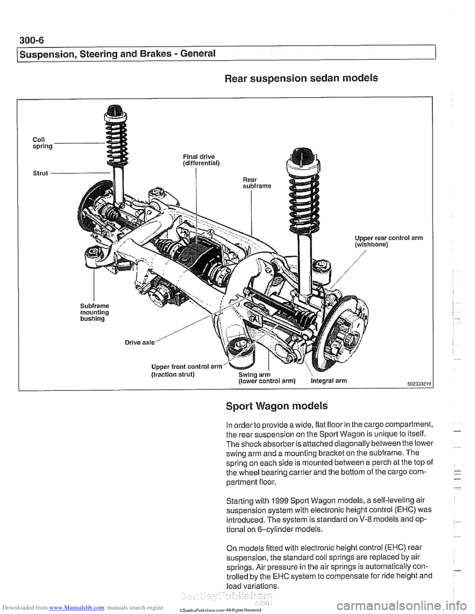
Rear suspension sedan models
Coil spring
Strut
-
'01 arm
Sport Wagon models
In order to provide a wide, ilat iloor in the cargo compartment,
the rear suspension on the Sport Wagon is unique to itself.
The shoclcabsorber is attached diagonally between the lower
swing arm and a mounting bracket on the subframe. The
spring on each side is mounted between a perch at the top
oi
the wheel bearing carrier and the bottom of the cargo com-
partment floor.
Starting with
1999 Sporl Wagon models, a self-leveling air
suspension system with electronic height control (EHC) was introduced. The system is standard on
V-8 models and op-
tional on 6-cylinder models.
On models fitted with electronic height control (EHC) rear
suspension, the standard coil springs are replaced by air
springs. Air pressure in the air springs is automatically con-
trolled by the
EHC system to compensate for ride height and
load variations.
Page 632 of 1002
Downloaded from www.Manualslib.com manuals search engine
300-1 2
I Sus~ension, Steerincl and Brakes - General
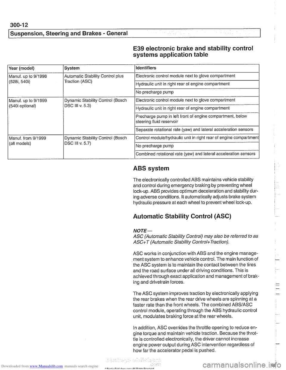
E39 electronic brake and stability control
systems application table
(528i, 54bi) Traction (ASC) I Hydraulic unit in right rear of engine compartment 1
Identifiers
Year (model)
I No precharge pump 1
Manuf. up to 911998 l~utomatic Stability Control plus I Electronic control module next to glove compartment
System
Precharge pump in
lefl front of engine compartment, below
steering fluid reservoir
Separate rotational rate (yaw) and lateral acceleration sensors
I I
Combined rotational rate (yaw) and lateral acceleration sensors
Electronic control
module next to glove compartment
Hydraulic unit in right rear of engine compartment
Manuf. up to 911999
(540i optional)
I I
ABS system
Dynamic Stability Control (Bosch
DSC
Ill v. 5.3)
The electronically controlled
ABS maintains vehicle stability
and control during emergency braking by preventing wheel
lock-up.
ABS provides optimum deceleration and stability dur-
ing adverse conditions. It automatically adjusts brake system
hydraulic pressure at each wheel to prevent wheel lock-up.
Control
moduleihydraulic unit
in right rear of engine compartment
No precharge pump
Manuf. from
911999
(all models)
Automatic Stability Control (ASC)
Dynamic Stability Control (Boscli
DSC Ill v. 5.7)
NOJE-
ASC (Automatic Stability Control) may also be referred to as
ASCiT (Automatic Stability ControkTraction).
ASC works in conjunction with ABS and the engine manage-
ment system to enhance vehicle control. The main function of
the
ASC system is to maintain the contact between the tires
and the road surface under all driving conditions. This is
achieved through exact application and management of brak-
ing and drivetrain forces.
The
ASC system improves traction by electronically applying
the rear brakes when the rear drive wheels are spinning at a
faster rate than the front wheels. The combined
ABSIASC
control module, operating through the ABS hydraulic control
unit, modulates braking force at the rear wheels.
In addition,
ASC overrides the throttle opening to reduce en-
gine torque and maintain vehicle traction. Because the throt-
tle is controlled electronically, the driver cannot increase
engine power output during
ASC intervention regardless of
how far the accelerator pedal is pushed.
Page 633 of 1002
Downloaded from www.Manualslib.com manuals search engine
Suspension, Steering and Brakes - ~enerail
The main components of the system are the wheel speed
(pulse) sensors, the
ABSIASC or ABSIDSC control module,
and the hydraulic control unit.
Traction control also comes into operation during decelera-
tion. Decelerating on snowy or icy road surfaces can lead to
rear wheel slip. If a rear wheel starts to drag or lock up, the
ASC system can limit the problem by adjusting throttle, fuel
injection and ignition timing.
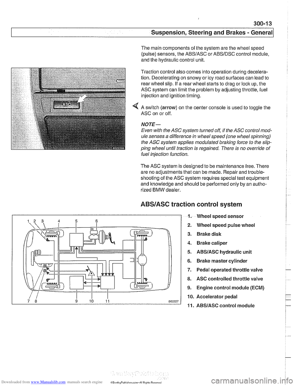
4 A switch (arrow) on the center console is used to toggle the
ASC on or off.
NOJE-
Even with the ASC system turned off, if the ASC control mod-
ule senses a difference in wheel speed (one wheel spinning)
the
ASC system applies modulated braling force to the slip-
ping wheel until traction is regained. There is no override of
fuelinjection function.
The ASC system is designed to be maintenance free. There
are no adjustments that can be made. Repair and trouble-
shooting of the ASC system requires special test equipment
and knowledge and should be performed only by an autho-
rized
BMW dealer.
ABSIASC traction
I 1.
control system
Wheel speed sensor
Wheel speed pulse wheel
Brake disk
Brake caliper
ABSIASC hydraulic unit
Brake master cylinder
Pedal operated throttle valve
ASC controlled throttle valve
Engine control module (ECM)
Accelerator pedal
ABSlASC control module
Page 634 of 1002
Downloaded from www.Manualslib.com manuals search engine
300-1 4
I Susoension. Steerina and Brakes - General
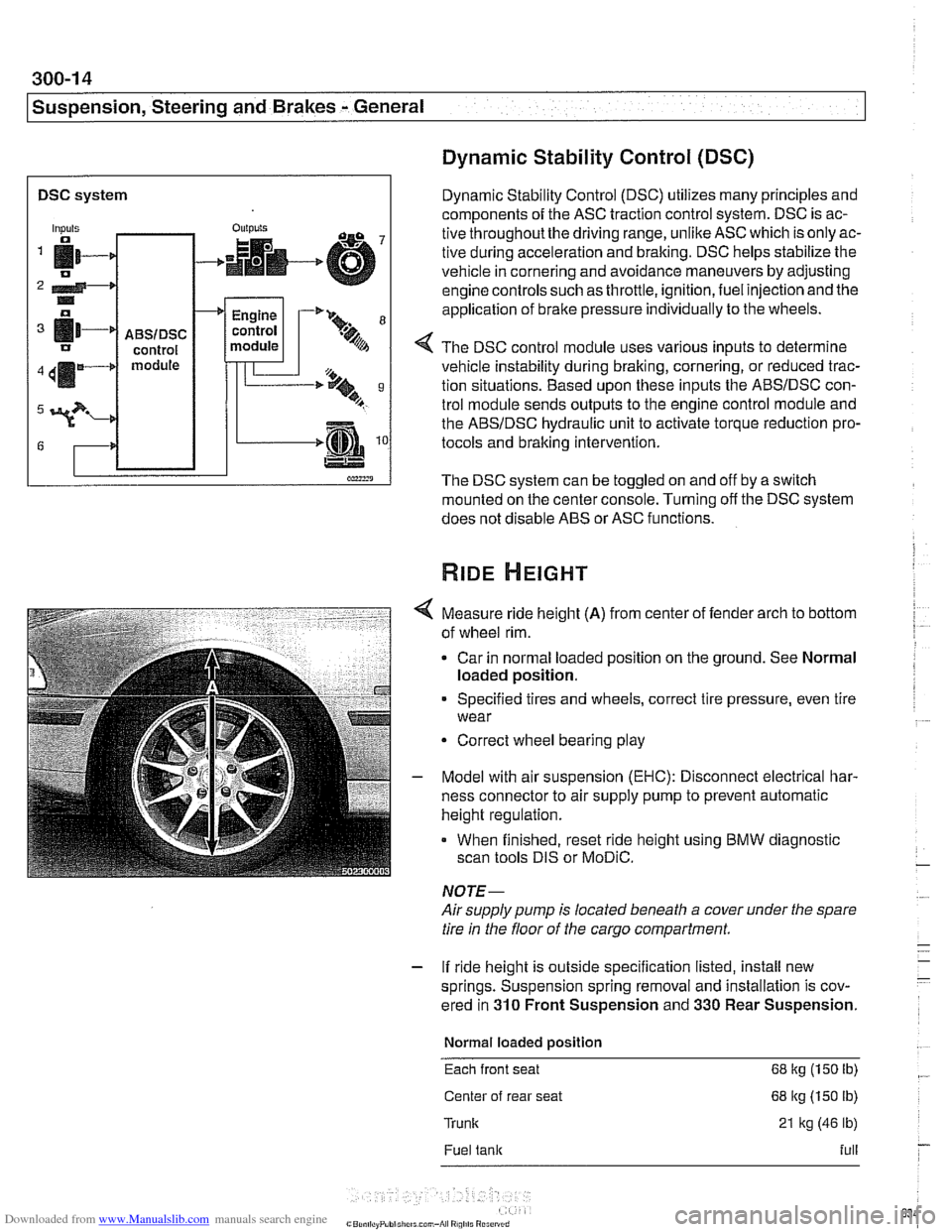
DSC system I
Dynamic Stability Control (DSC)
Dynamic Stability Control (DSC) utilizes many principles and
components of the ASC traction control system. DSC is ac-
tive throughoutthe driving range, unlike ASC which is only ac-
tive during acceleration and braking. DSC helps stabilize the
vehicle in cornering and avoidance maneuvers by adjusting
engine controls such as throttle, ignition, fuel injection and the
application of
brake pressure individually to the wheels.
Inputs
fi- 0
2 4-* .. o
[11-' IJ
411m4
3?-
G
4 The DSC control module uses various inputs to determine
vehicle instability during braking, cornering, or reduced trac-
tion situations. Based upon these inputs the ABSIDSC con-
trol module sends outputs to the engine control module and
the ABSIDSC hydraulic unit to activate torque reduction pro-
tocols and braking intervention.
-
ABSIDSC control module
OUI~YIS
4
The DSC system can be toggled on and off by a switch
mounted on the center console. Turning off the DSC system
does not disable ABS or ASC functions.
+
Measure ride height (A) from center of fender arch to bottom
of wheel rim.
Car in normal loaded position on the ground. See Normal
loaded position.
Engine
control
module
Specified tires and wheels, correct tire pressure, even tire
wear
-'* 9-
.%A
Correct wheel bearing play
T'== ..t, 9 B
-.m
Model with air suspension (EHC): Disconnect electrical har-
ness connector to air supply pump to prevent automatic
height regulation.
When finished, reset ride height using BMW diagnostic
scan tools DIS or
MoDiC.
NOTE-
Airsupply pump is located beneath a cover under the spare
tire in the floor of the cargo compartment.
- If ride height is outside specification listed, install new
springs. Suspension spring removal and installation is cov-
ered in
310 Front Suspension and 330 Rear Suspension.
Normal loaded position
Each front seat 68 kg (150 Ib)
Center of rear seat 68 kg (150 lb)
Trunk 21 kg (46 lb)
Fuel tank full
Page 635 of 1002
Downloaded from www.Manualslib.com manuals search engine
Suspension, Steering and Brakes - General
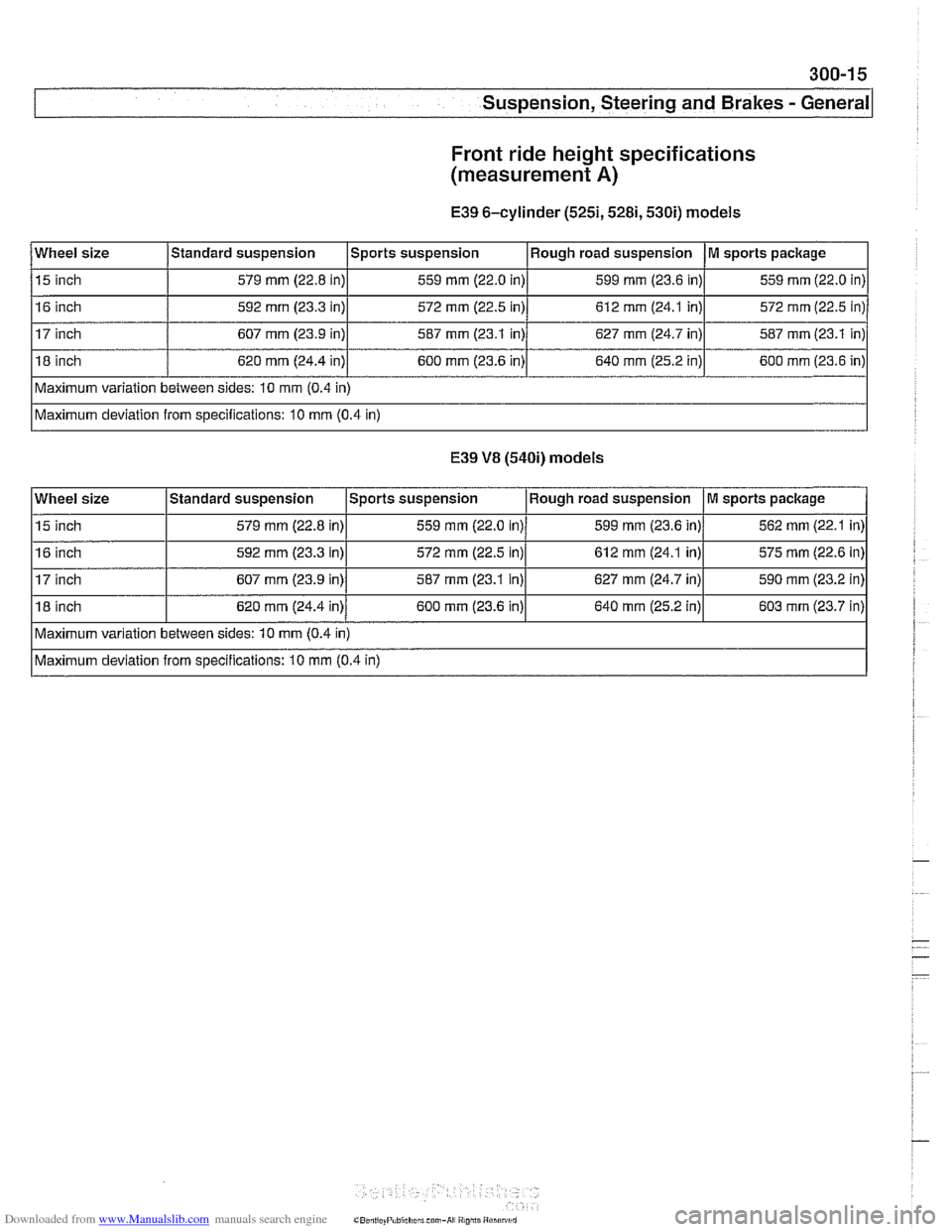
Front ride height specifications
(measurement
A)
E39 6-cylinder (5251,5281,530i) models
E39
V8 (540i) models
Wheel size
15 inch
16 inch
17 inch
18 inch
Maximum variation between sides: 10 mm (0.4 in)
Maximum deviation from specifications: 10 mm (0.4 in)
Standard
suspension
579 mm (22.8 in)
592 mm (23.3 in)
607 mm (23.9 in)
620 mm (24.4 in)
Wheel size
15 inch
16 inch
17 inch
18 inch Sports suspension
559
mm (22.0 in)
572 mm (22.5 in)
587 mm (23.1 in)
600 mm (23.6 in)
Maximum variation between sides: 10 mm (0.4 in)
Maximum deviation from specifications: 10 mm (0.4 in)
Standard
suspension
579 mm (22.8 in)
592
mm (23.3 in)
607 mm (23.9 in)
620 mm (24.4 in) Rough
road suspension
599
mm (23.6 in)
612 mm (24.1 in)
627 mm (24.7 in)
640 mm (25.2 in)
Sports suspension
559 mm (22.0 in)
572 mm (22.5 in)
587 mm (23.1 in)
600
mm (23.6 in)
M sports package
559 mm (22.0 in)
572 mm (22.5 in)
587 mm (23.1 in)
600 mm (23.6 in)
Rough road suspension 599 mm (23.6 in)
612
mm (24.1 in)
627
mm (24.7 in)
640
mm (25.2 in)
M sports package
562 mm (22.1 in)
575 mm (22.6 in)
590
mm (23.2 in)
603
mm (23.7 in)
Page 636 of 1002
Downloaded from www.Manualslib.com manuals search engine
300-1 6
I Suspension, Steering and Brakes - General
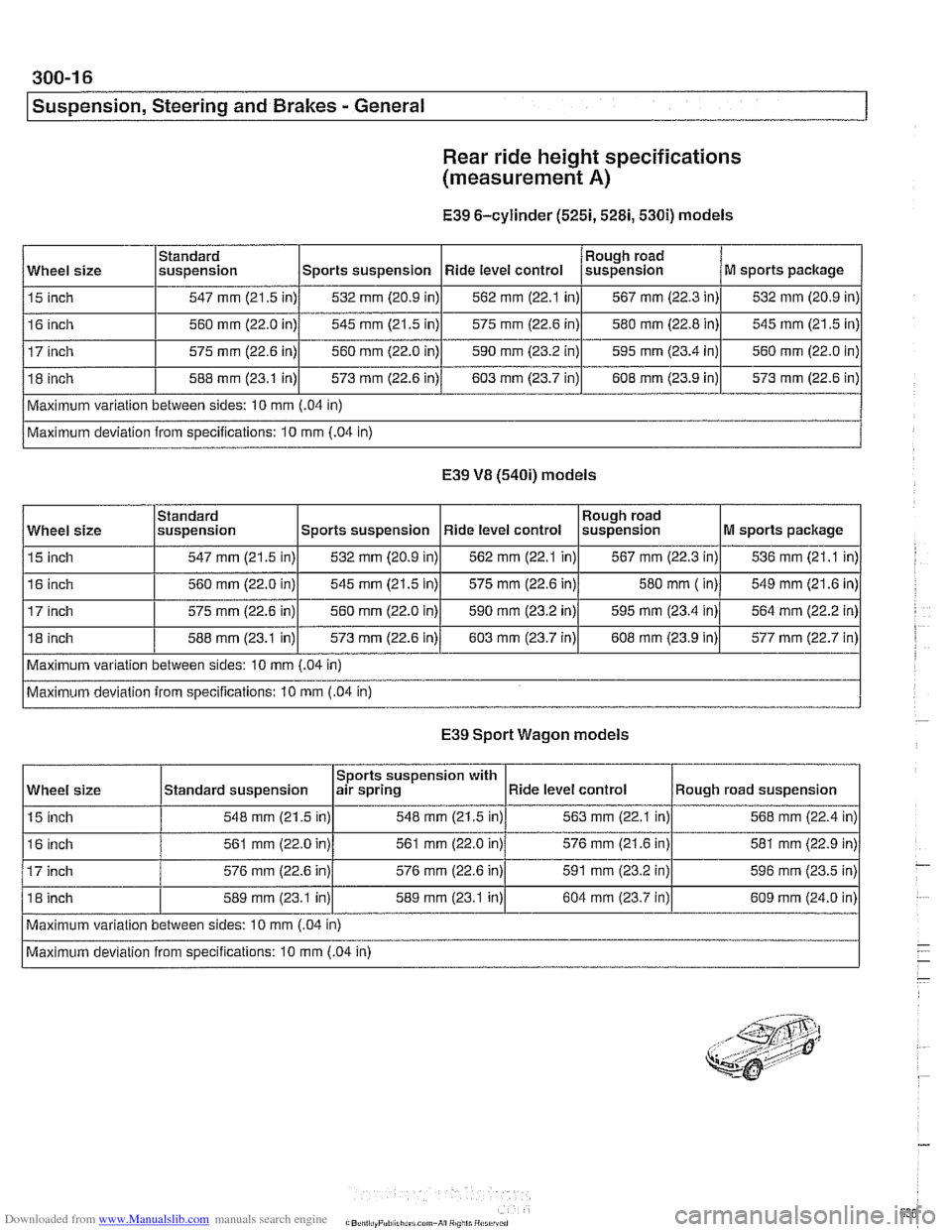
Rear
ride height specifications
(measurement
A)
E39 6-cylinder (5251,5281,530i) models
E39 VB (540i) models
Wheel size
15 inch
16 inch
17 inch
18 inch
Maximum variation between sides: 10
mm (.04 in)
Maximum deviation from specifications: 10
mm (.04 in)
Standard
suspension
547 mm (21.5 in)
560
mm (22.0 in)
575 mm (22.6 in)
588 mm (23.1 in)
I I I I I
Maximum variation between sides: 10 mm (.04 in)
Wheel
size
15 inch
16 inch
575 mm (22.6 in)
Maximum deviation from specifications: 10 mm
(.04 in)
Sports suspension
532 mm (20.9 in)
545 mm (21.5 in)
560 mm (22.0 in)
573
mm (22.6 in)
Rough road
suspension
567
mm (22.3 in)
580 mm
( in)
E39 Sport Wagon models
M sports package
536
mm (21.1 in)
549 mm (21.6 in)
Standard
suspension
547 mm (21.5 in)
560 mm (22.0 in)
588 mm (23.1
in)l 573 mm (22.6 in)/ 603 mm (23.7 in)l 608 mm (23.9 in)l 577 mm (22.7 in)
560
mm (22.0
in) Ride level
control
562
mm (22.1 in)
575 mm (22.6 in)
590 mm (23.2 in)
603 mm (23.7 in)
Sports suspension 532
mm (20.9 in)
545 mm (21.5 in)
590
mm (23.2 in) Rough
road
suspension
567
mm (22.3 in)
580 mm (22.8 in)
595 mm (23.4 in)
608 mm (23.9 in)
Ride level control
562
mm (22.1 in)
575 mm (22.6 in)
Wheel size
15 inch
M sports package
532
mm (20.9 in)
545
mm (21.5 in)
560 mm (22.0 in)
573 mm (22.6 in)
595
mm (23.4 in)
Sports suspension with
air spring
548 mm (21.5 in)
Standard
suspension
548
mm (21.5 in)
16 inch
17 inch
18 inch 564
mm (22.2
in)
Maximum variation between sides: 10 mm
(.04 in)
Maximum deviation from specifications: 10 mm
(.04 in) 561
mm (22.0 in)
576
mm (22.6 in)
589
mrn (23.1 in)
561
mm (22.0 in)
576 mm (22.6 in)
589 mm (23.1 in) Ride level
control
563
mm (22.1 in) Rough road suspension
568 mm (22.4 in)
576 mm (21.6 in)
591 mm (23.2 in)
604 mm (23.7 in) 581
mm (22.9
in)
596
mm (23.5 in)
609 mm (24.0 in)
Page 638 of 1002
Downloaded from www.Manualslib.com manuals search engine
31 0-2
I Front Suspension
This repair group covers the repair and replacement of com-
ponents that make up the front suspension of E39 cars.
Two different types of steering systems are used in the E39
series. 6-cylinder
(5251,5281 and 530i) models are equipped
with a rack and pinion type steering system mounted to an
aluminum subframe.
V-8 (540i) models use a steering gear-
box type system mounted to a steel subframe.
See
300 Suspension, Steering and Brakes-General for a
description of the front suspension and components, as well
as specifications for setting ride height.
CAUTION-
Some E39 models are equipped with aluminum suspen-
sion components. The foiiowing cautions apply:
Due to the chemical and corrosion characteristics of
aluminum, do not bring into contact with battery acid.
* Do not clean with wire brushes with brass or iron bris-
ties. Only use brushes with stainless steei bristles.
Do not expose to flying sparks from grinding/cutting op-
erations.
* Do not subject to steei welding splashes.
Do not expose to temperatures over 80°C (176°F).
even for short periods. Temperatures in painting faciii-
ties are not a problem.
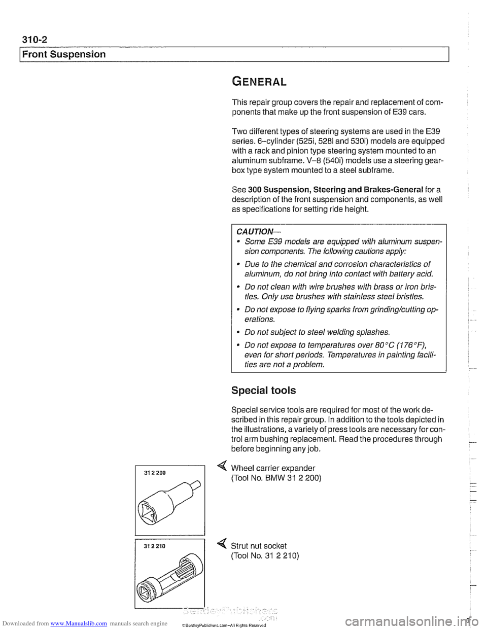
Special tools
Special service tools are required for most of the work de-
scribed in this repair group. In addition to the tools depicted in
the illustrations, avariety of press tools are necessaryfor con-
trol arm bushing replacement. Read the procedures through
before beginning any job.
31 2 210 I < Strut nut socket
(Tool No. 31 2 210)