torque BMW 540i 2000 E39 Owners Manual
[x] Cancel search | Manufacturer: BMW, Model Year: 2000, Model line: 540i, Model: BMW 540i 2000 E39Pages: 1002
Page 311 of 1002
Downloaded from www.Manualslib.com manuals search engine
Camshaft Timing Chain1
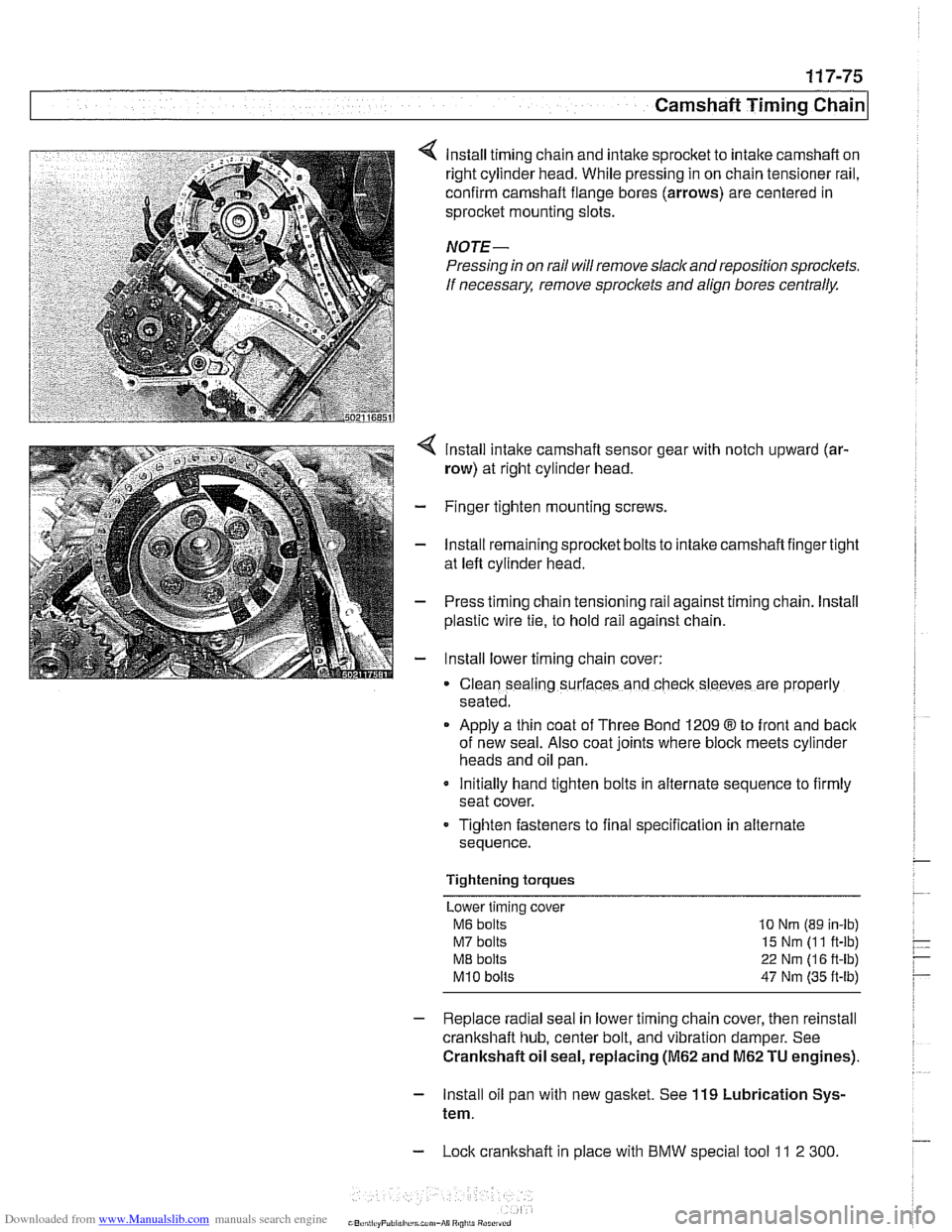
lnstall timing chain and intake sprocket to intake camshaft on
right cylinder head. While pressing in on chain tensioner rail,
confirm camshaft flange bores (arrows) are centered in
sprocket mounting slots.
NOTE-
Pressing in on rail will remove slack and reposition sprockets.
If
necessarx remove sproclets and align bores centrally.
lnstall intake camshaft sensor gear with notch upward (ar-
row) at right cylinder head.
- Finger tighten mounting screws.
- lnstall remaining sprocket bolts to intake camshaft finger tight
at left cylinder head.
- Press timing chain tensioning rail against timing chain. lnstall
plastic wire
tie, to hold rail against chain.
- lnstall lower timing chain cover:
Clean sealing surfaces and check sleeves are properly
seated.
Apply a thin coat of Three Bond 1209
8 to front and back
of new seal. Also coat joints where block meets cylinder
heads and oil pan.
Initially hand tighten bolts in alternate sequence to firmly
seat cover.
Tighten fasteners to final specification in alternate
sequence.
Tightening torques Lower timing cover
M6 bolts 10 Nrn (89 in-lb)
M7 bolts 15 Nm (1 1 ft-lb)
ME bolts 22 Nm (1 6 ft-lb)
M10 bolts 47 Nm (35 ft-lb)
- Replace radial seal in lower timing chain cover, then reinstall
crankshaft hub, center bolt, and vibration damper. See
Crankshaft oil seal, replacing
(M62 and M62 TU engines).
- lnstall oil pan with new gasket. See 119 Lubrication Sys-
tem.
- Lock crankshaft in place with BMW special tool 11 2 300
Page 312 of 1002
Downloaded from www.Manualslib.com manuals search engine
1 17-76
/camshaft Timing Chain
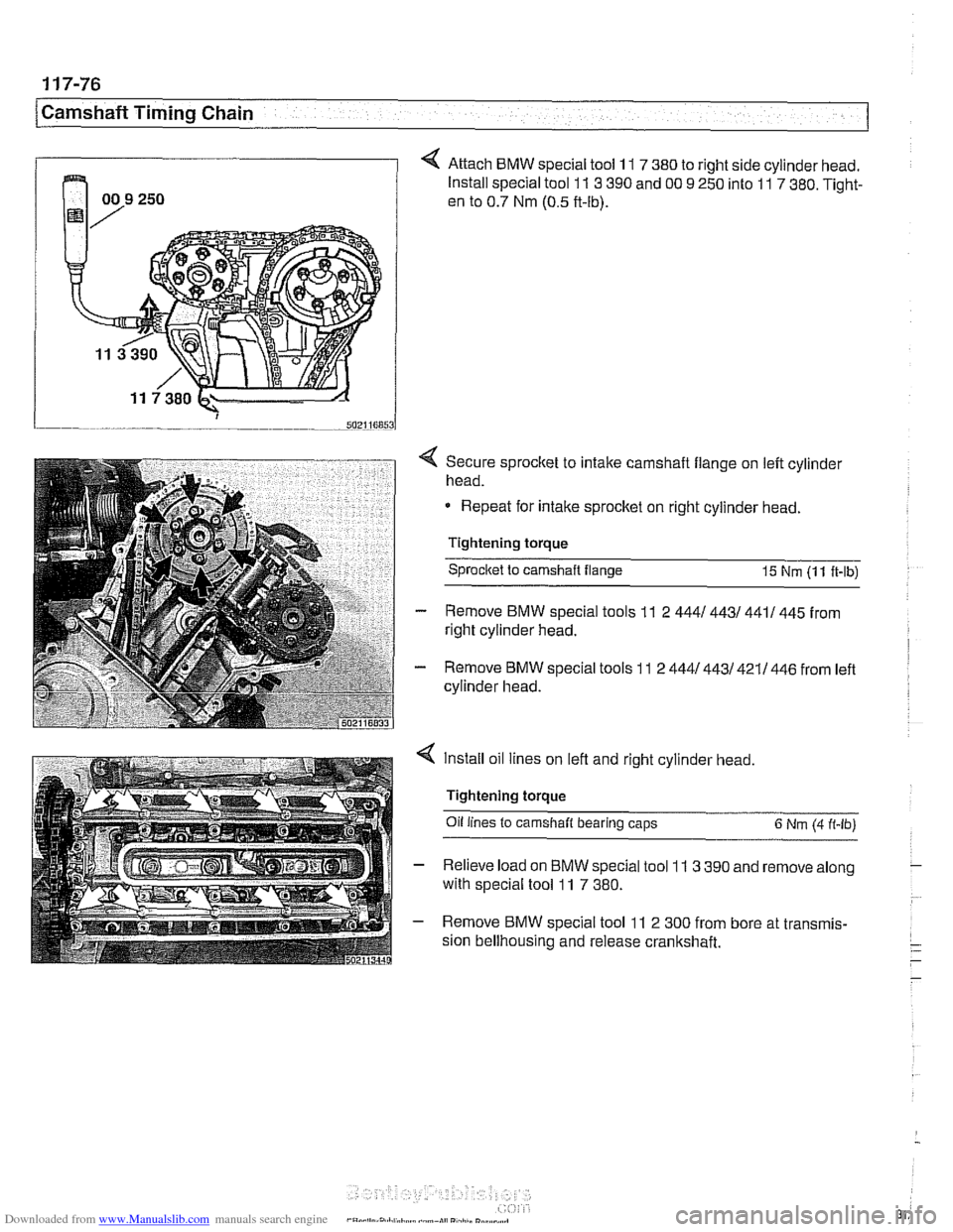
4 Attach BMW special tool 11 7 380 to right side cylinder head.
Install special tool
11 3 390 and 00 9 250 into 11 7 380. Tight-
en to 0.7 Nm (0.5 ft-lb).
4 Secure sprocket to intake camshaft flange on left cylinder
head.
Repeat for intake sprocket on right cylinder head.
Tightening torque Sprocltet to camshaft flange
15 Nm (1 1 ft-lb)
- Remove BMW special tools 11 2 4441 4431 4411 445 from
right cylinder head.
- Remove BMW special tools 11 2 4441443/421/446 from left
cylinder head.
4 Install oil lines on left and right cylinder head,
Tightening torque
Oil
lines to camshaft bearing caps 6 Nm (4 ft-lb)
- Relieve load on BMW special tool 11 3 390 and remove along
with special tool
11 7 380.
- Remove BMW special tool 11 2 300 from bore at transmis-
sion bellhousing and release crankshaft.
Page 313 of 1002
Downloaded from www.Manualslib.com manuals search engine
Camshaft Timing Chain
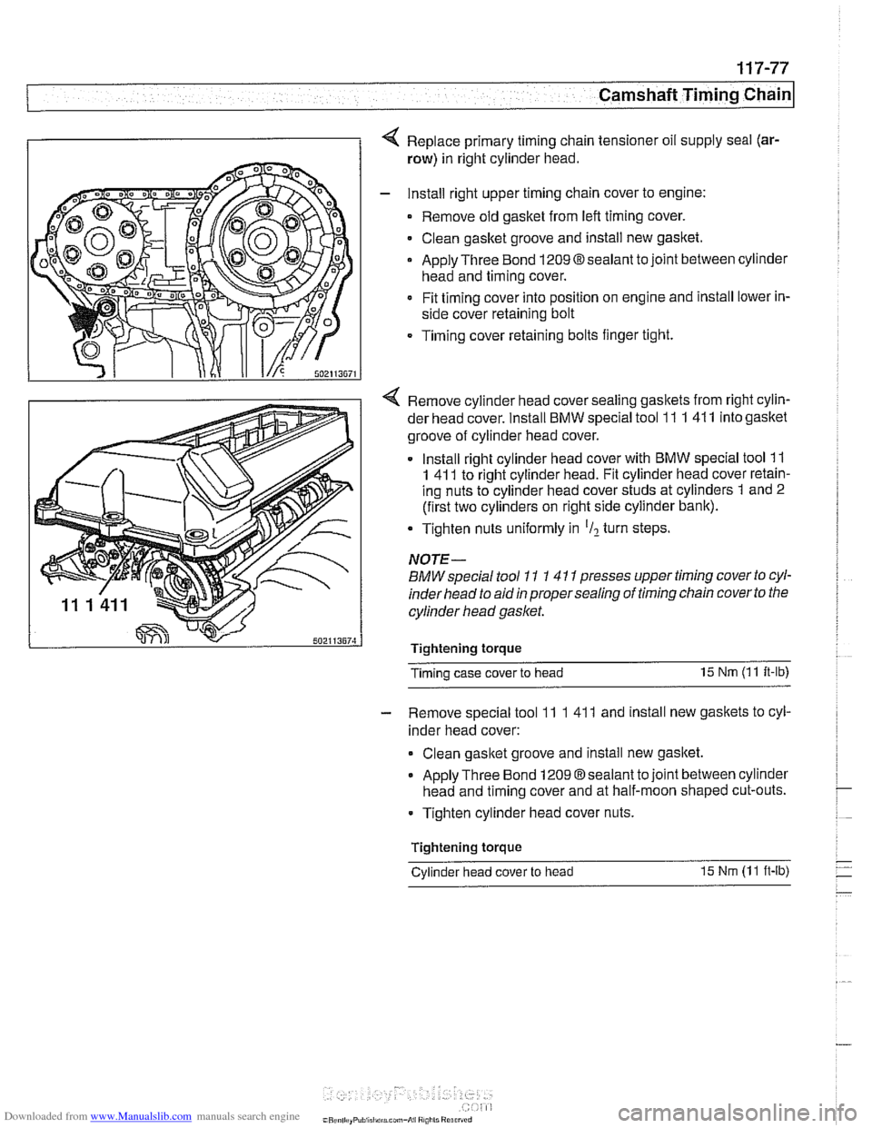
4 Replace primary timing chain tensioner oil supply seal (ar-
row) in right cylinder head.
- Install right upper timing chain cover to engine:
Remove old gasket from
left timing cover.
Clean gasket groove and install new gasket.
Apply Three Bond
1209Osealant to joint between cylinder
head and timing cover.
Fit timing cover into position on engine and install lower in-
side cover retaining bolt
Timing cover retaining bolts finger tight.
4 Remove cylinder head cover sealing gaskets from right cylin-
der head cover. Install
BMW special tool 11 1 41 1 into gasltet
groove of cylinder head cover.
Install right cylinder head cover with
BMW special tool 11
1 41 1 to right cylinder head. Fit cylinder head cover retain-
ing nuts to cylinder head cover studs at cylinders 1 and 2
(first two cylinders on right side cylinder bank).
Tighten nuts uniformly in
'Il turn steps.
NOTE-
BMW special tool 11 1 4 11 presses upper timing cover to cyl-
inder head to aid
in proper sealing of timing chain cover to the
cylinder head gasket.
Tightenlng torque
Timing case cover to head 15
Nm (1 1
It-lb)
- Remove special tool 11 1 41 1 and install new gaskets to cyl-
inder head cover:
Clean gasltet groove and install new gasltet.
Apply Three Bond 1209 Osealant to joint between cylinder
head and timing cover and at half-moon shaped cut-outs.
Tighten cylinder head cover nuts.
Tightenlng torque
-
Cylinder head cover to head 15 Nm (1 1 ft-lb)
Page 314 of 1002
Downloaded from www.Manualslib.com manuals search engine
[camshaft Timina Chain
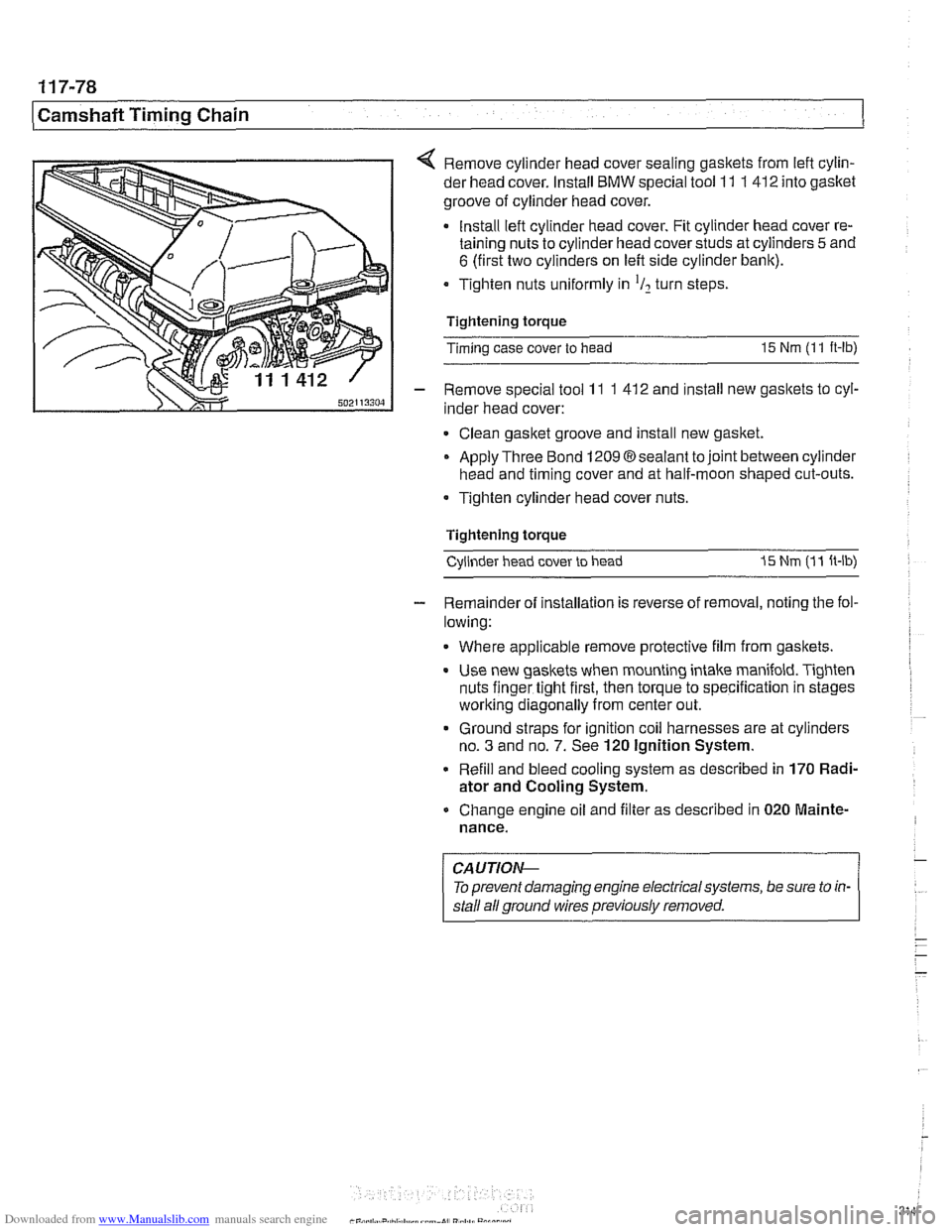
< Remove cylinder head cover sealing gaskets from lefl cylin-
der head cover. Install
BMW special tool 11 1 412 into gasket
groove of cylinder head cover.
Install lefl cylinder head cover. Fit cylinder head cover re-
taining nuts to cylinder head cover studs at cylinders
5 and
6 (first two cylinders on left side cylinder bank).
Tighten nuts uniformly in
'I2 turn steps
Tightening torque
Timing case cover to head
15 Nm (1 1 ft-lb)
- Remove special tool 11 1 41 2 and install new gaskets to cyl-
inder head cover:
Clean gasket groove and install new gasket.
Apply Three Bond
12098sealant tojoint between cylinder
head and timing cover and at half-moon shaped cut-outs.
Tighten cylinder head cover nuts.
Tightening torque Cylinder head cover to head
I5 Nm (1 1 ft-lb)
- Remainder of installation is reverse of removal, noting the fol-
lowing:
Where applicable remove protective film from gaskets.
Use new gaskets when mounting intake manifold. Tighten
nuts finger tight first, then torque to specification in stages
worlting diagonally from center out.
Ground straps for ignition coil harnesses are at cylinders
no.
3 and no. 7. See 120 Ignition System.
Refill and bleed cooling system as described in
170 Radi-
ator and Cooling System.
Change engine oil and filter as described in
020 Mainte-
nance.
CAUTIOI\C
To prevent damaging engine electrical systems, be sure to in-
stall ail ground wires previously removed.
Page 318 of 1002
Downloaded from www.Manualslib.com manuals search engine
[camshaft Timina Chain Cylinders
1-4
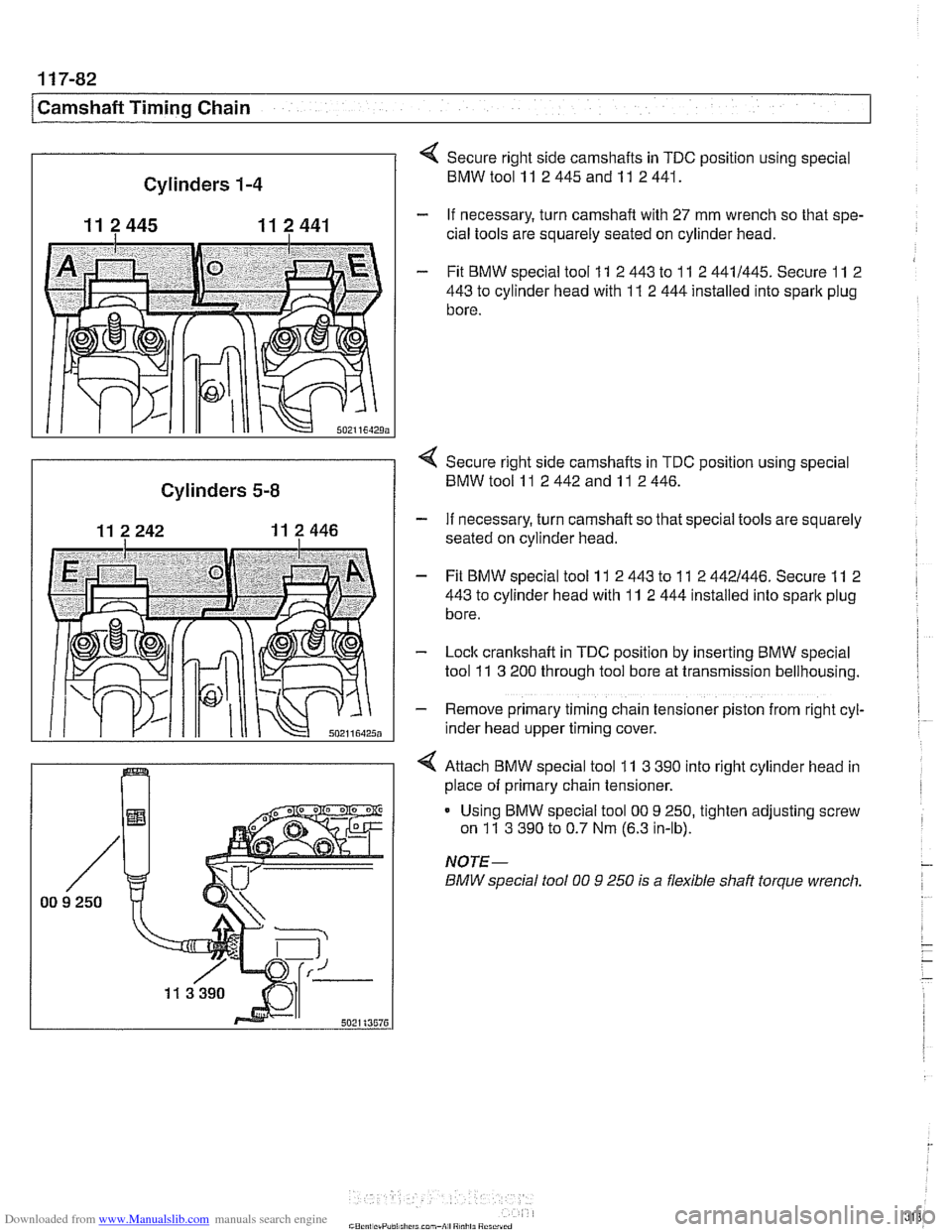
11 2445 11 2 441
502116429;
Secure right side camshafts in TDC position using special
BMWtoolll 2445andll 2441.
- If necessary, turn camshaft with 27 mm wrench so that spe-
cial tools are squarely seated on cylinder head.
- Fit BMW special tool 11 2 443 to 11 2 4411445. Secure 11 2
443
to cylinder head with 11 2 444 installed into spark plug
bore.
I
< Secure right side camshafts in TDC position using special
Cylinders 5-8 BMW tool 11 2 442 and 11 2 446.
- If necessary, turn camshaft so that special tools are squarely
seated on cylinder head.
- Fit BMW special tool 11 2 443 to 11 2 4421446. Secure 11 2
443
to cylinder head with 11 2 444 installed into spark plug
bore.
- Lock cranltshaft in TDC position by inserting BMW special
tool
11 3 200 through tool bore at transmission bellhousing.
- Remove primary timing chain tensioner piston from right cyl-
~nder head upper timing cover.
4 Attach BMW special tool 11 3 390 into right cylinder head in
place of primary chain tensioner.
Using BMW special tool
00 9 250, tighten adjusting screw
on
11 3 390 to 0.7 Nm (6.3 in-lb).
NOTE-
BMW special fool 00 9 250 is a flexible shaft torque wrench.
Page 319 of 1002
Downloaded from www.Manualslib.com manuals search engine
Camshaft Timing chain/
- Tighten accessible sprocket retaining bolts in the following
order:
Leit exhaust camshaft
Right exhaust
camshait
Leit intake camshaft
Right
intalte camshait
Tightening torque
Sprocket bolts to camshaft flange
15 Nm (1 1 ft-lb)
- Remove BMW special tool 11 2 300 from tool bore at bell-
housing and remove
camshaft loclting tools from cylinder
heads.
Using crankshaft center bolt, turn engine over clockwise at
least one
comolete rotation so that remainino camshaft
sprocltet
retaking bolts are accessible. -
- Tighten remaining camshait sprocket retaining bolts
Tightening torque Sprocket bolts to camshaft
flange 15 Nm (I 1 It-lb)
- Remove BMW special tool 11 3 390 from primary timing
chain tensioner bore and reinstall primary chain tensioner
- Remainder of installation is reverse or removal, noting the fol-
lowing:
Remove gasket residue from cylinder head sealing sur-
face.
Apply a thin bead of Three Bond 1209
O sealing com-
pound to joints at cylinder head cover and timing case cov-
er and at half-moon sections at rear of cylinder heads.
Replace cylinder head cover
gaskets if necessary.
Page 322 of 1002
Downloaded from www.Manualslib.com manuals search engine
11 9-2
Lubrication System
This repair group covers lubrication system troubleshooting
as well as oil pan removal and oil pump replacement.
In 6-cylinder models, removal of the oil pan requires the re-
moval of the exhaust system and some front suspension
components. Those procedures are fully covered in:
180 Exhaust System
210 Clutch
230 Manual Transmission
0 240 Automatic Transmission
310 Front Suspension
320 Steering and Wheel Alignment
NOTE-
Oil change procedure and oil filter replacement are covered
in
020 Maintenance.
CAUTIOG
V8 engines: The oil pump fasteners (including the sprocket
retaining nut) are known to vibrate loose. This can result in oil
starvation and engine failure. Be sure to check oil bolts and
nut tightness whenever the
oilpump is accessible. If any fas-
teners are found to be loose, remove them and reinstall with
Loctite
Band torque to specifications.
Special tools
The engine needs to be properly supported while the front
suspension
subframe is lowered to access the oil pan.
A standard oil pressure gauge may be used for measuring oil
pressure.
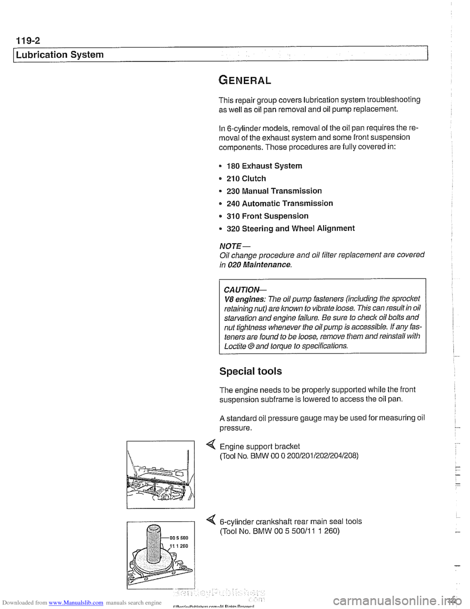
Engine support bracket
(Tool No, BMW 00 0 20012011202~2041208)
4 6-cylinder crankshalt rear main seal tools
(Tool No. BMW 00 5 50011
1 1 260)
Page 325 of 1002
Downloaded from www.Manualslib.com manuals search engine
. .- -
L
- --
- - -. - -- Lubrication ~~stern
- Remove pressure gauge and reinstall pressure switch with
new sealing washer.
Tightening torque
Oil pressure switch to oil filter housing 27 Nm (20 ft-lb)
If testing shows low oil pressure, one or more of the following
conditions may be indicated:
Worn or faulty oil pump or faulty pump pressure relief valve
Worn or damaged engine bearings
Severe engine wear
Any of these conditions indicate the need for major repairs.
Oil pressure warning system, testing
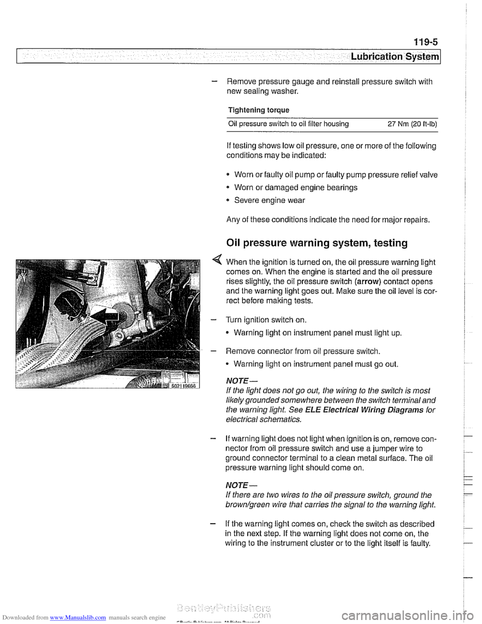
4 When the ignition is turned on, the oil pressure warning light
comes on. When the engine is started and the oil pressure
rises slightly, the oil pressure switch (arrow) contact opens
and the warning light goes out. Make sure the oil level is cor-
rect before making tests.
- Turn ignition switch on.
- Warning light on instrument panel must light up
- Remove connector from oil pressure switch.
Warning light on instrument panel must go out.
NOTE-
If the light does not go out, the wiring to the switch is most
likely grounded somewhere between the switch terminaland
the warning light See
ELE Electrical Wiring Diagrams for
electrical schematics.
- If warning light does not light when ignition is on, remove con-
nector from oil pressure switch and use a jumper wire to
ground connector terminal to a clean metal surface. The oil
pressure warning light should come on.
NOTE-
If there are two wires to the oil pressure switch, ground the
brown/green wire that carries the signal to the warning light.
- If the warning light comes on, check the switch as described
in the next step. If the warning light does not come on, the
wiring to the instrument cluster or to the light itself is faulty.
Page 327 of 1002
Downloaded from www.Manualslib.com manuals search engine
Lubrication stern/
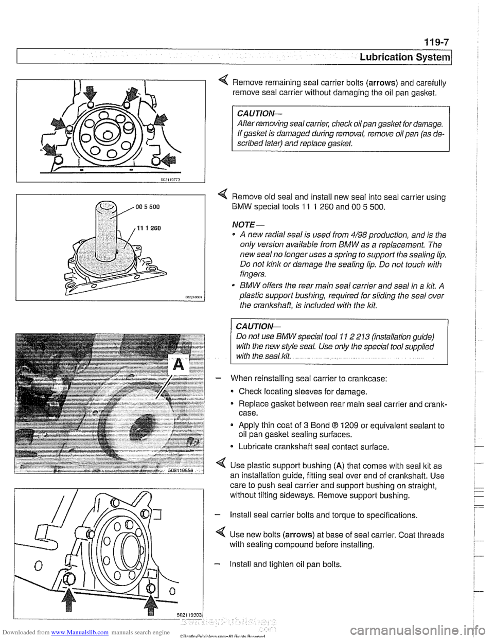
Remove remaining seal carrier bolts (arrows) and carefully
remove seal carrier without damaging the oil pan
gasltet.
CAUTION-
After removing seal carrier, checlc oilpan gasket for damage.
If gasket is damaged during removal, remove oil pan (as de-
scribed later) and replace
gasket.
< Remove old seal and install new seal into seal carrier using
BMW special tools
11 1 260 and 00 5 500.
NOTE-
A new radial seal is used from 4/98 production, and is the
only version available from
BMW as a replacement. The
new
sealno longer uses a spring to support the sealing lip.
Do not
lcinlc or damage the sealing lip. Do not touch with
fingers.
* BMW offers the rear main seal carrier and seal in a lit A
plastic support bushing, required for sliding the seal over
the crankshaft, is included with the
lcit.
I CAUTION- 1
Do not use BMW special tool 1 I 2 213 (mstallation guide)
with the new style seal. Use only the special tool
supphed
with the seal lcit.
When reinstalling seal carrier to crankcase:
Check locating sleeves for damage.
Replace
gasltet between rear main seal carrier and crank-
case.
Apply thin coat of
3 Bond 8 1209 or equivalent sealant to
oil pan gasket sealing surfaces.
* Lubricate crankshaft seal contact surface.
Use plastic support bushing
(A) that comes with seal ltit as
an installation
quide, fittina seal over end of crankshaft. Use - -
care to push seal carrier and support bushing on straight,
without tilting sideways. Remove support bushing.
- lnstall seal carrier bolts and torque to specifications.
4 Use new bolts (arrows) at base of seal carrier. Coat threads
with sealing compound before installing.
- Install and tighten oil pan bolts.
Page 328 of 1002
Downloaded from www.Manualslib.com manuals search engine
I Lubrication System -
- Remainder of assembly is reverse of disassembly.
Install flywheel, clutch or torque converter and
transmission.
Fill engine with oil.
- Run engine and check for leaks.
Tightening torques
Oil
drain plug fo oil pan (MI21 25 Nm (18 ft-lb)
Oil pan to engine
block
M6 (8.8 grade) 10 Nm (89 in-ib)
M6 (1 0.9 grade) 12 Nm (9 ft-lb)
M8 (8.8 grade) 22 Nm (1 6 it-lb)
Rear main seal carrier to crankcase
M6 10 Nm (89 in-lb)
ME 22 Nm (16 ft-lb)
Crankshaft rear main seal, replacing (V-8)
- Remove transmission. See 230 Manual Transmission or
240 Automatic Transmission.
- Manual transmission vehicles: Remove clutch pressure plate
and disc. See
210 Clutch.
- Remove flywheel. See 210 Clutch.
- Drain engine oil.
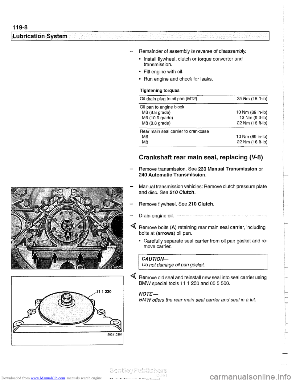
4 Remove bolts (A) retaining rear main seal carrier, including
bolts at (arrows) oil pan.
Carefully separate seal carrier from oil pan gasket and re-
move carrier.
CAUTION-
Do not damage oil pan gasket.
< Remove old seal and reinstall new seal into seal carrier using
) BMW special tools 11 1 230 and 00 5 500.