torque BMW 540i 2000 E39 Workshop Manual
[x] Cancel search | Manufacturer: BMW, Model Year: 2000, Model line: 540i, Model: BMW 540i 2000 E39Pages: 1002
Page 488 of 1002
Downloaded from www.Manualslib.com manuals search engine
/ ~uel Tank and Fuel Pump
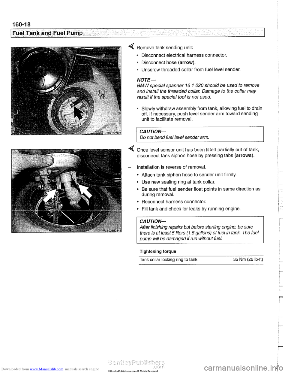
4 Remove tank sending unit:
Disconnect electrical harness connector.
Disconnect hose (arrow).
- Unscrew threaded collar from fuel level sender.
NOTE-
BMW special spanner 16 1 020 should be used to remove
and install the threaded collar. Damage to the collar may
result if the special tool is not used.
Slowly withdraw assembly from tank, allowing fuel to drain
off. If necessary, push level sender arm toward sending
unit to facilitate removal.
CA UTIOW-
Do not bend fuel level sender arm.
4 Once level sensor unit has been lifted partially out of tank,
disconnect tank siphon hose by pressing tabs (arrows).
- Installation is reverse of removal
Attach tank siphon hose to sender unit firmly.
Use new sealing ring at tank collar.
. Be sure that fuel sender float points in same direction as
during removal.
- Reconnect harness connector.
Fill tank and
check for leaks by running engine.
CAUTION-
After finishing repairs but before starting engine, be sure
there is at least
5 liters (1.5gallons) of fuel in tan/(. The fuel
pump will be damaged if run without fuel.
Tightening
torque
Tank collar loclting rlng to tanlt 35 Nm (26 lb-ft) -
Page 492 of 1002
Downloaded from www.Manualslib.com manuals search engine
160-22
Fuel Tank and Fuel Pump
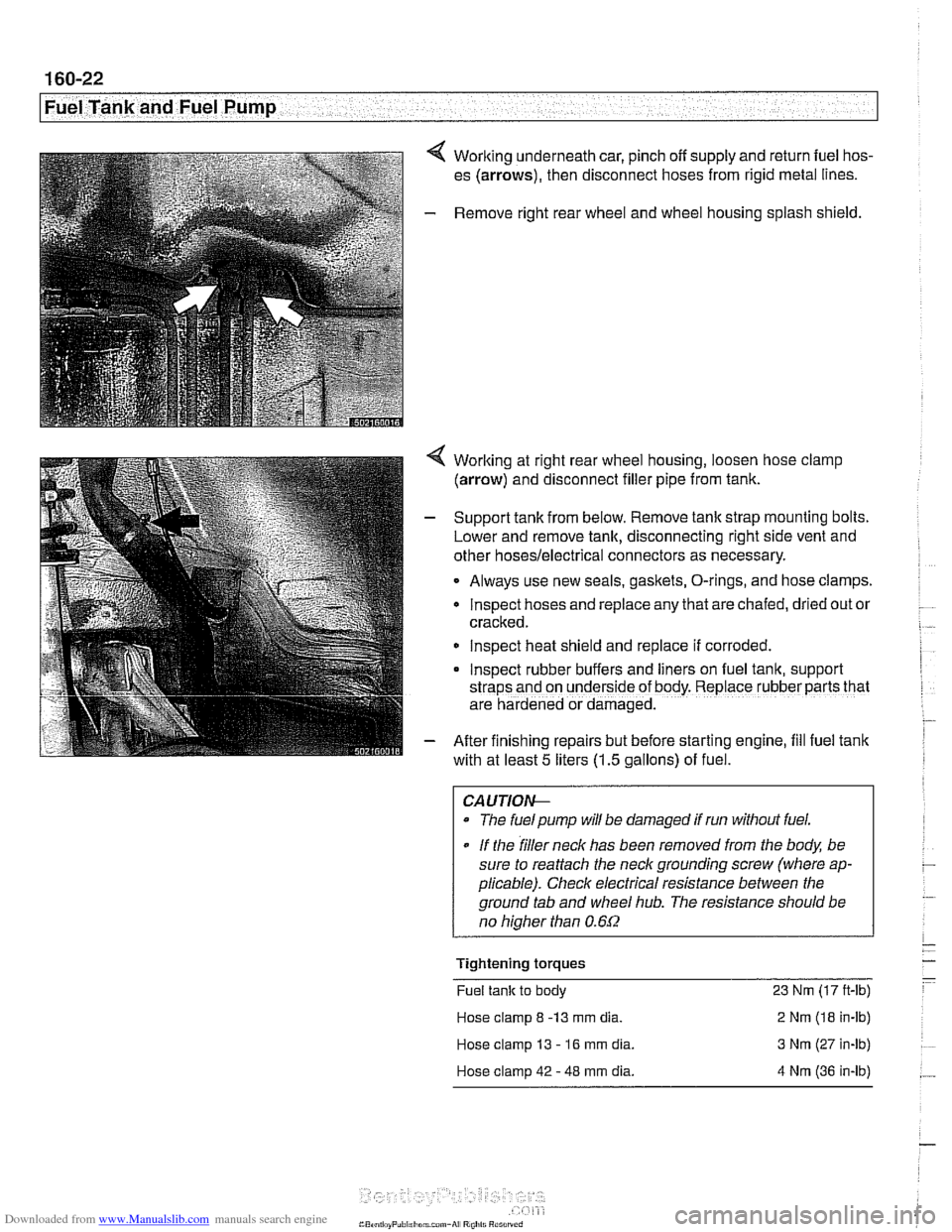
4 Working underneath car, pinch off supply and return fuel hos-
es (arrows), then disconnect hoses from rigid metal lines.
- Remove right rear wheel and wheel housing splash shield.
4 Worlting at right rear wheel housing, loosen hose clamp
(arrow) and disconnect filler pipe from tank.
- Support tank from below. Remove tank strap mounting bolts.
Lower and remove tank, disconnecting right side vent and
other
hoses/electrical connectors as necessary.
Always use new seals, gaskets, O-rings, and hose clamps.
lnspect hoses and replace any that are chafed,
dr~ed out or
cracked.
lnspect heat shield and replace if corroded.
Inspect rubber buffers and
hers on fuel tank, support
straps and on underside of body. Replace rubber parts that
are hardened or damaged.
- After finishing repairs but before starting engine, fill fuel tank
with at least
5 liters (1.5 gallons) of fuel.
CAUTlOI+
The fuelpump will be damaged if run without fuel.
* If the filler neck has been removed from the body, be
sure to reattach the
neck grounding screw (where ap-
plicable). Check electrical resistance between the
ground tab and wheel
hub. The resistance should be
no
hiaher than 0.6f2
Tightening torques
Fuel tank to body 23 Nm (17 ft-lb)
Hose clamp
8 -13 mm dia. 2 Nm (18 in-lb)
Hose clamp 13
- 16 mm dia. 3 Nm (27 in-lb)
Hose clamp 42
- 48 mm dia. 4 Nm (36 in-lb)
Page 493 of 1002

Downloaded from www.Manualslib.com manuals search engine
.- Fuel Tank and Fuel pump( -
Fuel expansion tank, removing
and installing
- Raise rear end of car and support safely.
CA U TIOG
Make sure the car is stable and well supported at all times.
Use a professional automotive lift
orjack stands designed for
the
ouroose. A floor iack is not adequate support
- Remove left rear wheel and wheel housing inner shield.
4 Remove plastic nut (A) and disconnect hose (B).
4 Tilt vent tank down and loosen or cut off hose clamps
(arrows). Pull hoses off fittings.
- Release vacuum line loclting clips and remove tank
- Installation is reverse of removal. Use new hose clamps.
Tightening torques
Hose clamp 8 - 13 mm dia. 2 Nrn (18 in-lb)
Hose clamp 13 - 16 mm dia. 3 Nm (27 in-lb)
Hose clamp
42 - 48 mm dia. 4 Nm (36 in-lb)
Page 494 of 1002
Downloaded from www.Manualslib.com manuals search engine
Fuel Tank and Fuel Pump 1
Activated carbon canister I fuel tank leak
detection unit
(LDP or DMTL), removing . . -
and installing
- Raise rear end of car and support safely.
CAUTION-
Make sure the car is stable and well supported at all times.
Use a professional automotive lift
orjack stands designed for
the purpose.
A floor jack is not adequate support.
- Remove left rear wheel and inner fender panel
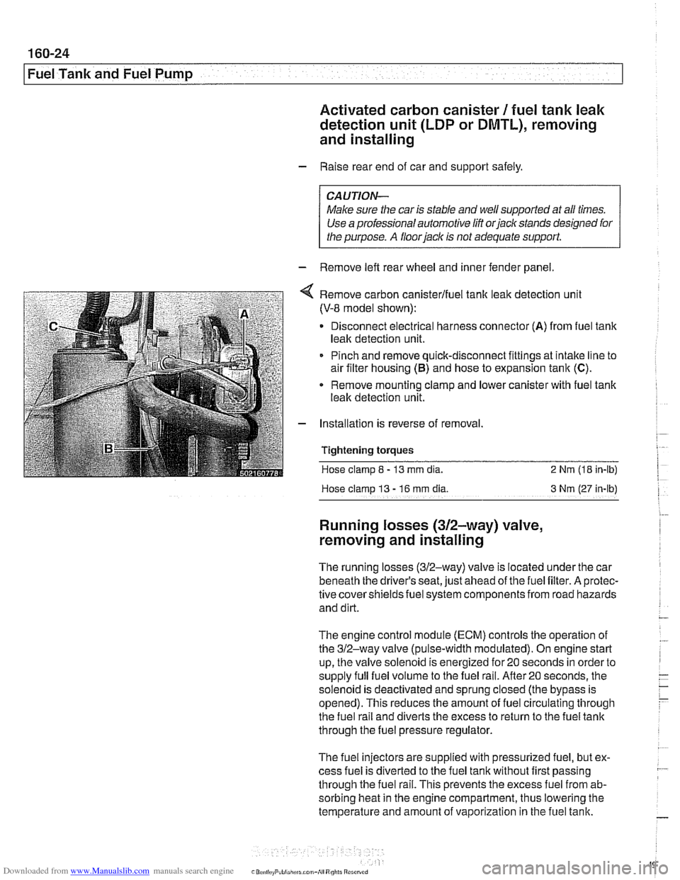
Remove carbon canisterlfuel tank leak detection unit
(V-8 model shown):
Disconnect electrical harness connector
(A) from fuel tank
leak detection unit.
Pinch and remove quick-disconnect fittings at intake line to
air filter housing
(5) and hose to expansion tank (C).
* Remove mounting clamp and lower canister with fuel tank
leak detection unit.
Installation is reverse of removal.
Tightening
torques
Hose clamp 8 - 13 mm dia. 2 Nrn (18 in-lb)
Hose clamp
13 - 16 rnm dia 3 Nm (27 in-lb)
Running losses (312-way) valve,
removing and installing
The running losses (312-way) valve is located under the car
beneath the driver's seat, just ahead of the fuel filter. A protec-
tive covershieldsfuel system components from road hazards
and dirt.
The engine control module
(ECM) controls the operation of
the 312-way valve (pulse-width modulated). On engine start
up, the valve solenoid is energized for 20 seconds in order to
supply full fuel volume to the fuel rail.
After20 seconds, the
solenoid is deactivated and sprung closed (the bypass is
opened). This reduces the amount of fuel circulating through
the fuel rail and diverts the excess to return to the fuel tank
through the fuel pressure regulator.
The fuel injectors are supplied with pressurized fuel, but ex-
cess fuel is diverted to the fuel tank without first passing
through the fuel rail. This prevents the excess fuel from ab-
sorbing heat in the engine compartment, thus lowering the
temperature and amount of vaporization in the fuel tank.
Page 495 of 1002
Downloaded from www.Manualslib.com manuals search engine
160-25
Fuel Tank and Fuel pump1
The 312-way valve is also activated briefly if an engine misfire
is detected. This provides full fuel flow through the fuel rail to
determine if the misfire was caused by a lean fuel condition.
The valve is monitored by the ECM forfaults.
- Using BMW or compatible scan tool, read out fault memory.
See
OBD On-Board Diagnostics.
- Turn off ignition.
- Raise car and support safely.
CA UTIOW
Male sure the car is stable and well suppodedat all times.
Use a professional automotive lift
orjack stands designed for
the purpose.
A floor jack is not adequate support.
- Worlting under car beneath driver's seat, remove protective
panel from fuel filter and 312-way valve.
- Clamp off fuel lines at 312-way valve.
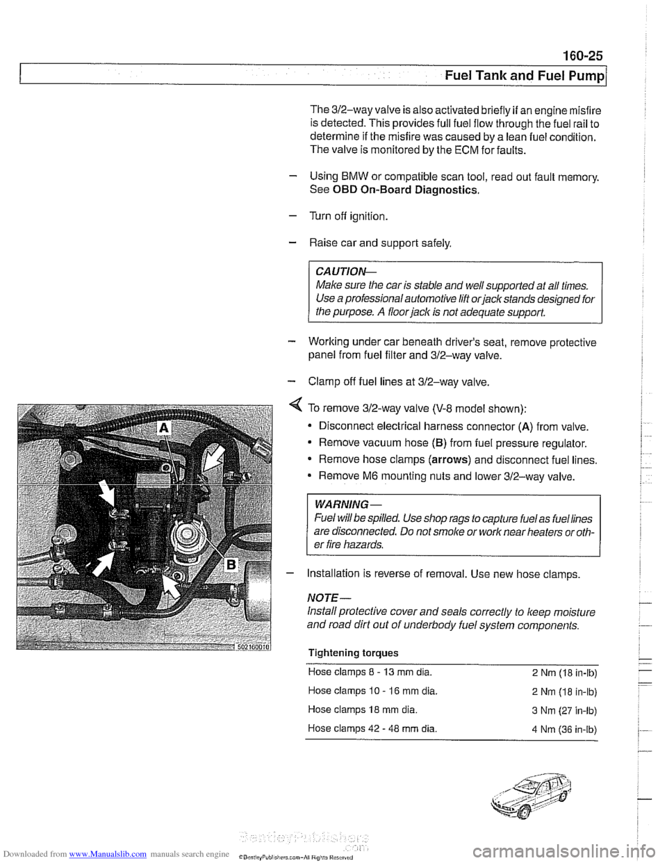
4 To remove 312-way valve (V-8 model shown):
Disconnect electrical harness connector
(A) from valve.
Remove vacuum hose
(B) from fuel pressure regulator.
* Remove hose clamps (arrows) and disconnect fuel lines.
Remove
M6 mounting nuts and lower 312-way valve.
WARNING-
Fuel will be spilled. Use shop rags to capture fuelas fuellines
are disconnected. Do not
smoke or work near heaters or oth-
er fire hazards.
- Installation is reverse of removal. Use new hose clamps
NOTE-
Install protective cover and seals correctly to keep moisture
and road dirt out of underbody fuel system components.
Tightening torques Hose clamps
8 - 13 mm dia.
2 Nm (18 in-lb)
Hose clamps
10 - 16 mm dia.
2 Nm (18 in-lb)
Hose clamps
18 mm dia. 3 Nm (27 in-lb)
Hose clamps 42
- 48 mm dia. 4 Nm 136 in-ib)
Page 508 of 1002
Downloaded from www.Manualslib.com manuals search engine
170-1 2
I Radiator and Cooling System
Tightening torques
Block drain plug to
block 25 Nm (1 8 ft-ib)
Radiator drain plug to radiator
2-3 Nm (18-27 in-lb)
Coolant, draining and filling (V-8 models)
WARNING -
Allow the cooling system to cool before opening or draining
the cooling system.
- Raise front of car and support safely.
I WARNING- 1
Make sure the car is stable and well supported at all times.
Use a professional automotive lift
orjack stands designed for
I the purpose. A floorjack is not adequate support 1
- Remove splash shield from under engine.
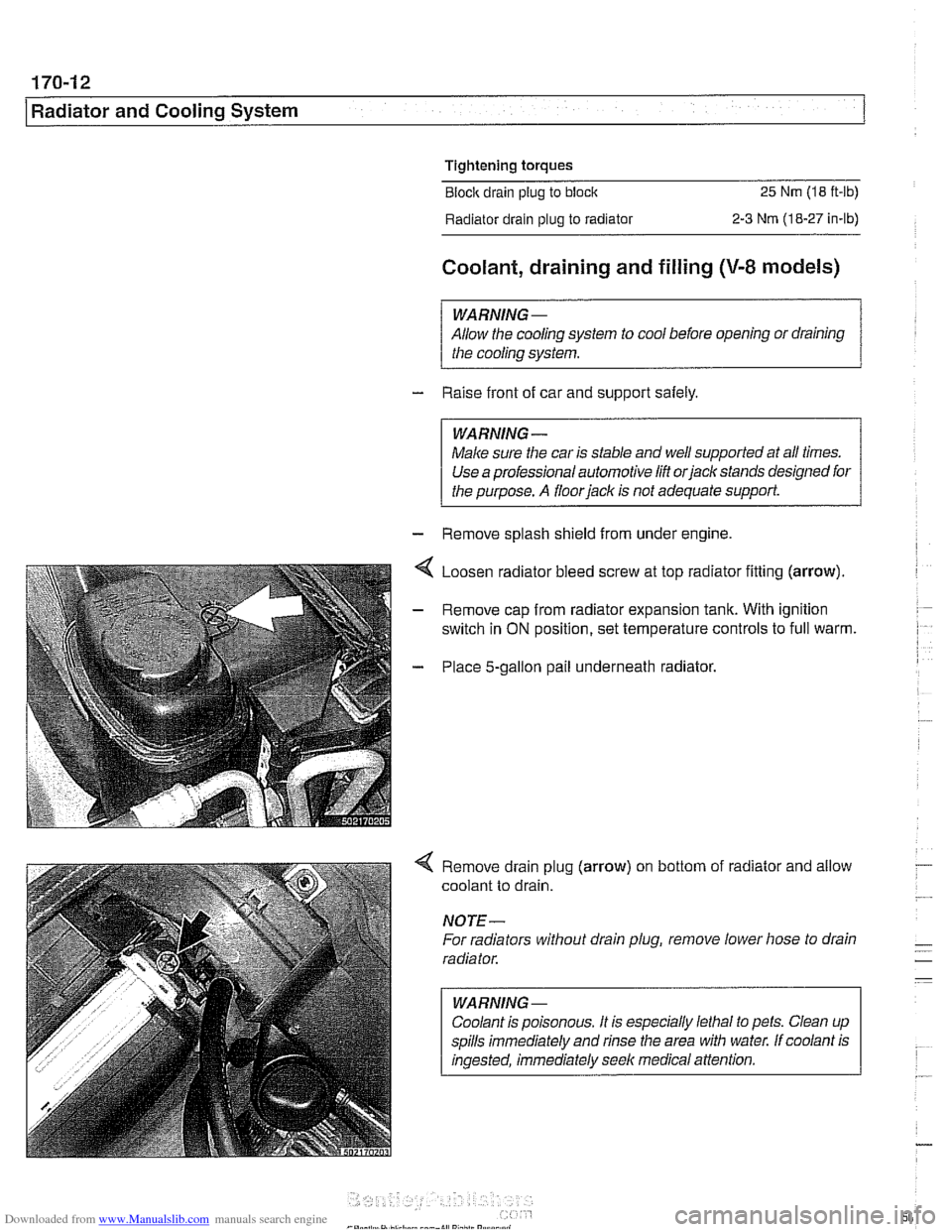
Loosen radiator bleed screw at top radiator fining (arrow).
Remove cap from radiator expansion tank. With ignition
switch in
ON position, set temperature controls to full warm.
Place 5-gallon pail underneath radiator.
4 Remove drain plug (arrow) on bottom of radiator and allow
coolant to drain.
NOTE-
For radiators without drain plug, remove lower hose to drain
radiator.
WARNING
-
Coolant is poisonous. It is especially lethal to pets. Clean up
spills immediately and rinse the area with water. If coolant is
ingested, immediately seek medical attention.
Page 509 of 1002
Downloaded from www.Manualslib.com manuals search engine
170-1 3
Radiator and Cooling ~vsteml
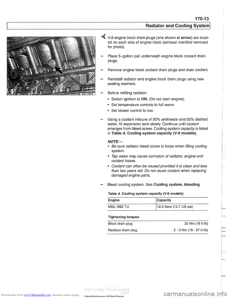
< V-8 engine bloclc drain plugs (one shown at arrow) are locat-
ed on each side of engine block (exhaust manifold removed
for photo).
- Place 5-gallon pail underneath engine block coolant drain
plugs.
- Remove engine bloclc coolant drain plugs and drain coolant.
- Reinstall radiator and engine block drain plugs using new
sealing washers.
- Before refilling radiator:
Switch ignition to
ON. (Do not start engine)
Set temperature controls to full warm.
- Set blower control to low.
- Using a coolant mixture of 50% antifreeze and 50% distilled
water, fill expansion tank slowly. Continue until coolant
emerges from bleed screw. Cooling system capacity is listed
in Tabled. Cooling system capacity
(V-8 models).
NOTE- Be sure radiator bleed screw is loose when filling cooling
system.
Tap water may cause corrosion of radiator, engine and
coolant hoses.
Coolant can often be reused provided it is clean and less
than two years old. Do not reuse coolant when replacing
damaged engine parts.
- Bleed cooling system. See Cooling system, bleeding
Tabled. Cooling system
capacity (V-8 models)
M62, M62 TU 12.0 liters (12.7 US qts)
Tightening torques
Block drain plug
25 Nm (18 ft-lb)
Radiator drain plug
2 - 3 Nm (18 - 27 in-lb)
Page 510 of 1002
Downloaded from www.Manualslib.com manuals search engine
Radiator and Cooling System
Cooling system, bleeding
Trapped air in the cooling system can prevent proper coolant
circulation and overheating. Wheneverthe coolant is drained
and filled, bleed the cooling system to remove trapped air.
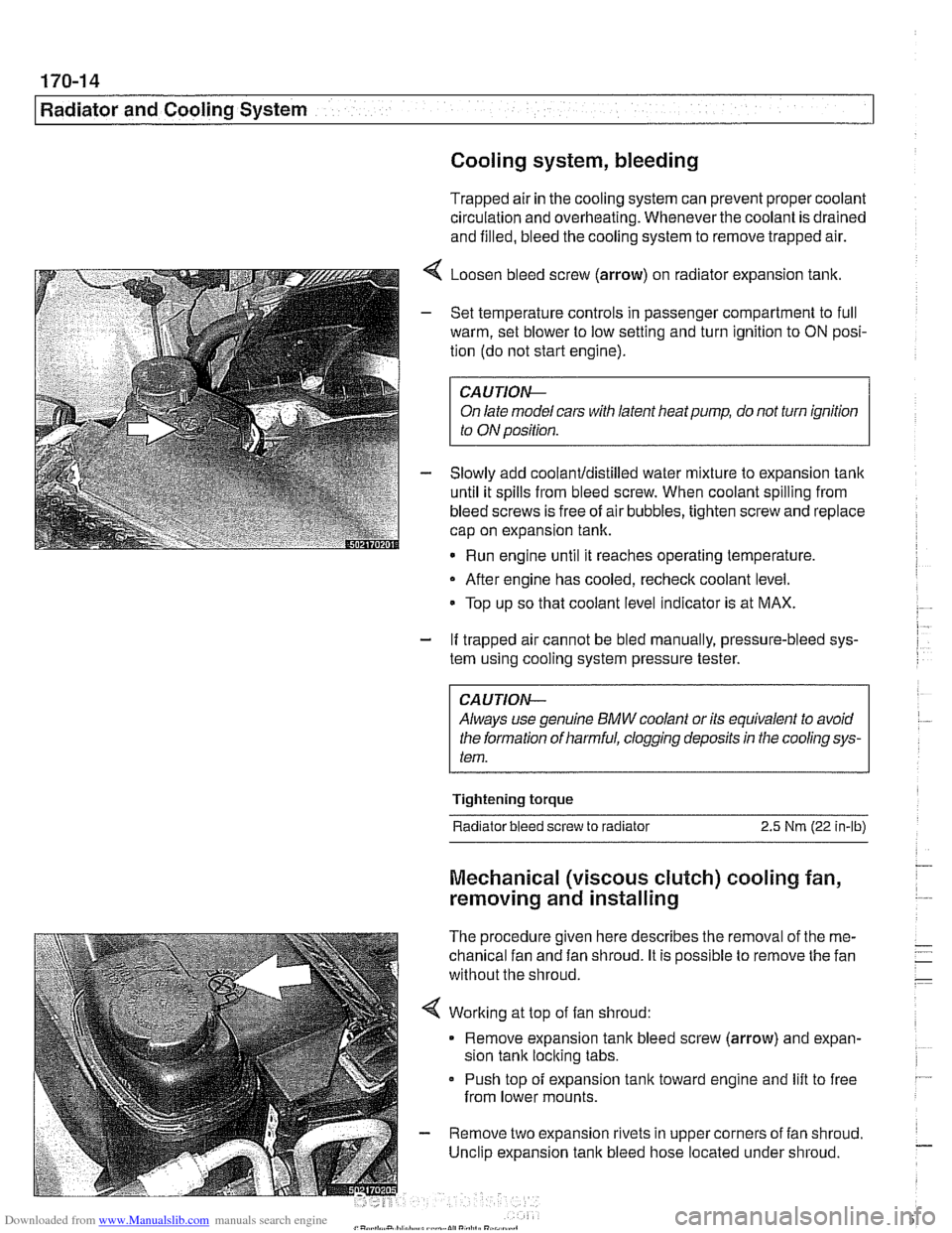
4 Loosen bleed screw (arrow) on radiator expansion tank.
- Set temperature controls in passenger compartment to full
warm, set blower to low setting and turn ignition to
ON posi-
tion (do not start engine).
CAUTIOIG
On late model cars with latent heat pump, do not turn ignition
to ON position.
- Slowly add coolanUdistilled water mixture to expansion tank
until it spills from bleed screw. When coolant spilling from
bleed screws is free of air bubbles, tighten screw and replace
cap on expansion tank.
Run engine until it reaches operating temperature,
- After engine has cooled, recheck coolant level.
Top up so that coolant level indicator is at MAX.
- If trapped air cannot be bled manually, pressure-bleed sys-
tem using cooling system pressure tester.
CA UTlON--
Always use genuine BMW coolant or its equivalent to avoid
the formation of harmful, clogging deposits
in the cooling sys-
tem.
Tightening torque
Radiator bleed screw to radiator 2.5 Nm (22 in-lb)
Mechanical (viscous clutch) cooling fan,
removing and installing
The procedure given here describes the removal of the me-
chanical fan and fan shroud. It is possible to remove the fan
without the shroud.
< Working at top of fan shroud:
Remove expansion tank bleed screw (arrow) and expan-
sion tank locking tabs.
Push top of expansion
tank toward engine and lift to free
from lower mounts.
- Remove two expansion rivets in upper corners of fan shroud.
Unclip expansion tank bleed hose located under shroud.
Page 511 of 1002
Downloaded from www.Manualslib.com manuals search engine
Radiator and Cooling System
Remove rubber trim strip between top of shroud and radiator.
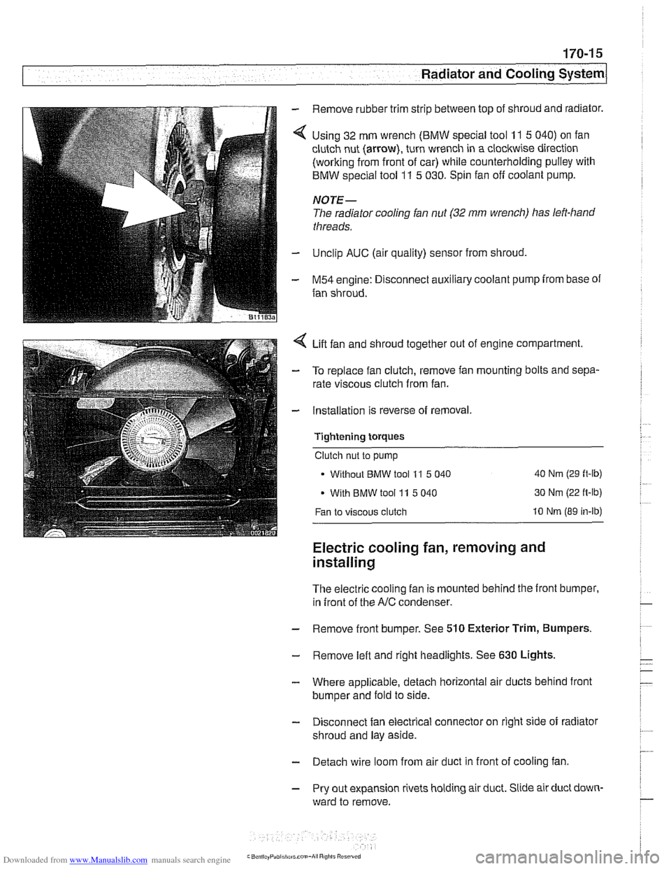
Using 32 mm wrench
(BMW special tool 11 5 040) on fan
clutch nut (arrow), turn wrench in a clockwise direction
(working from front of car) while counterholding pulley with
BMW special tool
11 5 030. Spin fan off coolant pump.
NOTE-
The radiator cooling fan nut (32 mm wrench) has left-hand
threads.
Unclip AUC (air quality) sensor from shroud,
M54 engine: Disconnect auxiliary coolant pump from base of
fan shroud.
Lift fan and shroud together out of engine compartment.
To replace fan clutch, remove fan mounting bolts and sepa-
rate viscous clutch from fan.
Installation is reverse of removal.
Tightening
torques
Clutch nut to pump
Without
BMW tool 11 5 040 40 Nm (29 ft-lb)
With BMW tool 11 5 040 30 Nm
(22 ft-lb)
Fan to viscous clutch 10 Nm (89 in-lb)
Electric cooling fan, removing and
installing
The electric cooling fan is mounted behind the front bumper,
in front of the
A/C condenser.
- Remove front bumper. See 510 Exterior Trim, Bumpers.
- Remove left and right headlights. See 630 Lights,
- Where applicable, detach horizontal air ducts behind front
bumper and fold to side.
- Disconnect fan electrical connector on right side of radiator
shroud and lay aside.
- Detach wire loom from air duct in front of cooling fan
- Pry out expansion rivets holding air duct. Slide air duct down-
ward to remove.
Page 513 of 1002
Downloaded from www.Manualslib.com manuals search engine
Radiator and Cooling systeml
Tightening torques
Block drain plug to block 25 Nm
(18
it-lb)
Coolant hose clamp (32 - 48 2.
5 Nm (22 in-lb)
mm hose diameter)
Radiator drain plug to radiator
2-3Nm(l8-27in-lb)
Thermostat housing to cylinder
head 10 Nm (89 in-lb)
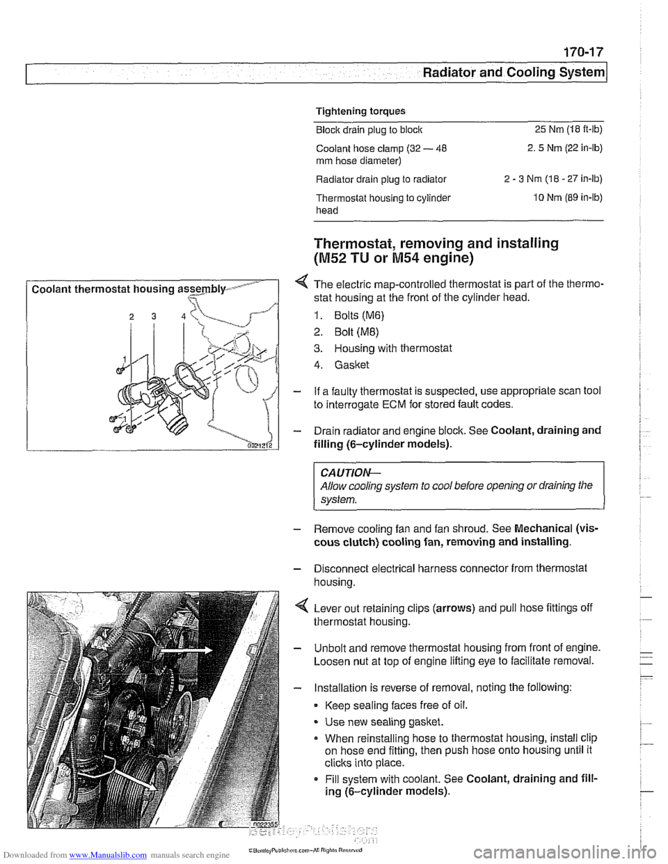
I Coolant thermostat housing assmbly- - I
Thermostat, removing and installing
(M52 TU or M54 engine)
4 The electric map-controlled thermostat is part of the thermo-
stat housing at the front of the cylinder head.
1. Bolts (M6)
2 Bolt (ME)
3. Housing with thermostat
4. Gasket
- If a faulty thermostat is suspected, use appropriate scan tool
to interrogate
ECM for stored fault codes.
- Drain radiator and engine block. See Coolant, draining and
filling (6-cylinder models).
CAUTION-
Allow cooling system to cool before opening or draining the
system.
- Remove cooling fan and fan shroud. See Mechanical (vis-
cous clutch) cooling fan, removing and installing.
- Disconnect electrical harness connector from thermostat
housina.
4 Lever out retaining clips (arrows) and pull hose fittings off
thermostat housing.
- Unbolt and remove thermostat housing from front of engine.
Loosen nut at top of engine lifting eye to facilitate removal.
- Installation is reverse of removal, noting the following:
Keep sealing faces free of oil.
* Use new sealing gasket.
When reinstalling hose to thermostat housing, install clip
on hose end fitting, then push hose onto housing until it
clicks into place.
Fill system with coolant. See Coolant, draining and fill-
ing (6-cylinder models).