Brake fluid BMW 540i 2000 E39 Service Manual
[x] Cancel search | Manufacturer: BMW, Model Year: 2000, Model line: 540i, Model: BMW 540i 2000 E39Pages: 1002
Page 792 of 1002
Downloaded from www.Manualslib.com manuals search engine
1 Brakes
- Remove precharge pump mounting bracket fasteners and re-
move pump.
- Installation is reverse of removal, noting the following:
Be sure to replace rubber pump mounts if damaged
01
worn.
Bleed brakes as described earlier.
Tightening torque Brake line
to precharge pump 18 Nrn (13 ft-lb)
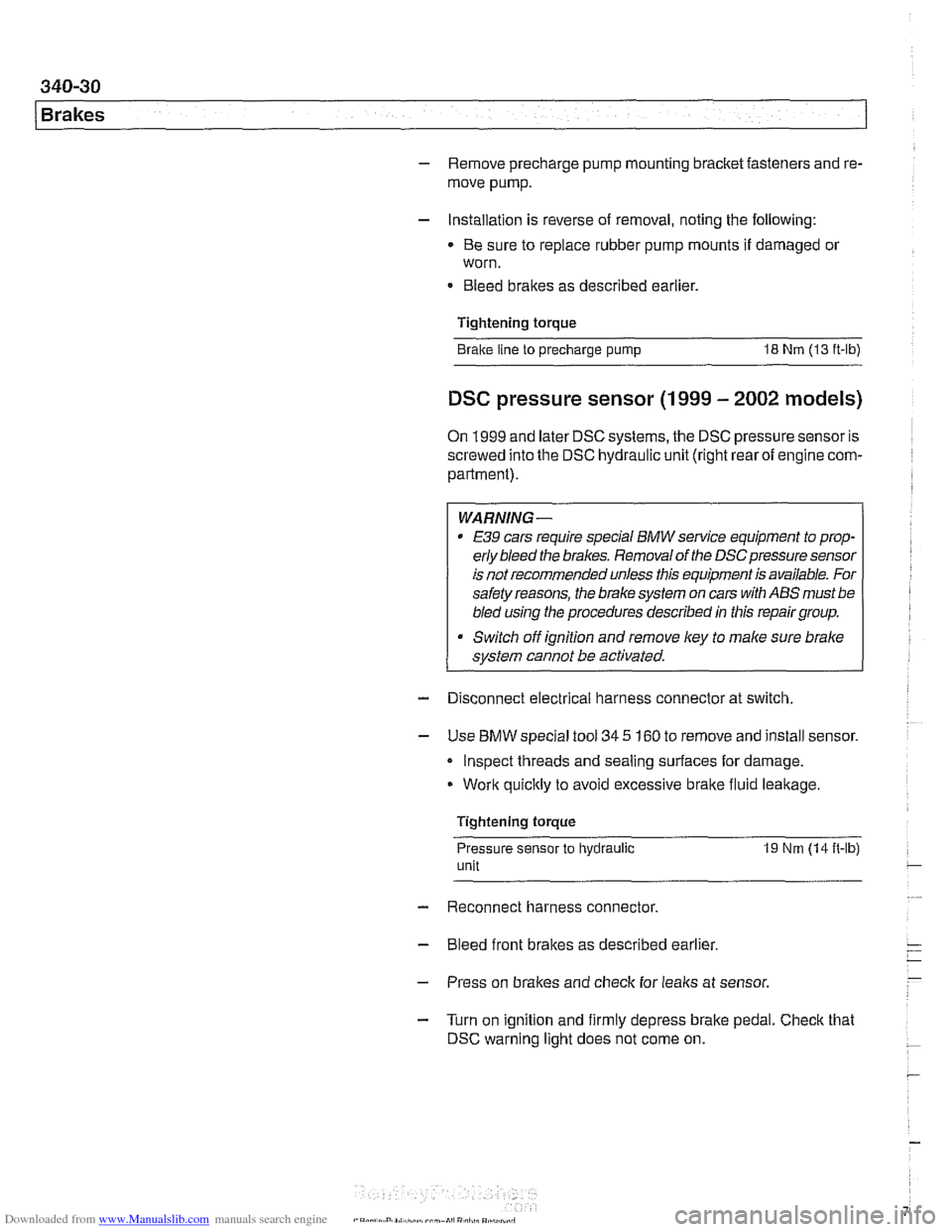
DSC pressure sensor (1 999 - 2002 models)
On 1999 and later DSC systems, the DSC pressure sensor is
screwed into the DSC hydraulic unit (right rear of engine com-
partment).
WARNING-
* €39 cars require special BMW service equipment to prop-
erly bleed the brakes. Removal of the
DSCpressure sensor
is not recommended unless this equipment is available. For
safety reasons, the brake system on cars with ABS must be
bled using the procedures described in this repair group.
Switch off ignition and remove
key to male sure brake
system cannot be activated.
- Disconnect electrical harness connector at switch.
- Use BMW special tool 34 5 160 to remove and install sensor.
Inspect threads and sealing surfaces for damage.
* Work quicltly to avoid excessive brake fluid leakage.
Tightening torque
Pressure sensor
to hydraulic 19 Nrn (14ft-lb)
unit
- Reconnect harness connector
- Bleed front brakes as described earlier.
- Press on brakes and check for leaks at sensor.
- Turn on ignition and firmly depress brake pedal. Check that
DSC warning light does not come on.
Page 794 of 1002
Downloaded from www.Manualslib.com manuals search engine
340-32
Brakes
The procedure for removing the ABS I ASC or ABS I DSC hy-
draulic unit is similar for all models. The unit is located at the
right rear of the engine compartment.
- Using a clean syringe, empty brake fluid reservoir.
CAUTION-
Brake fluid is highly corrosive and dangerous to the environ-
ment. Dispose of it
properiw
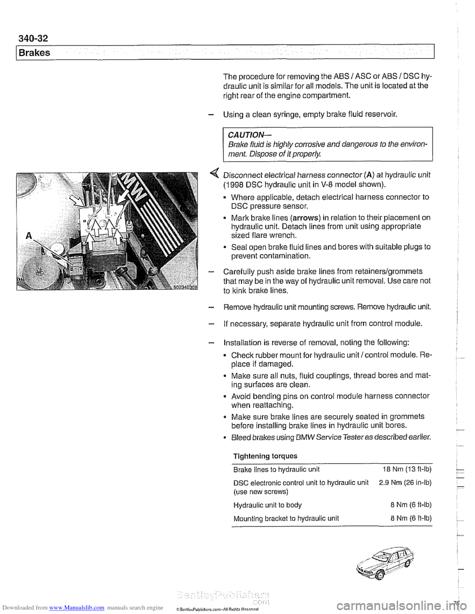
4 Disconnect electrical harness connector (A) at hydraulic unit
(1998 DSC hydraulic unit in V-8 model shown).
Where applicable, detach electrical harness connector to
DSC pressure sensor.
Mark brake lines
(arrows) in relation to their placement on
hydraulic unit. Detach lines from unit using appropriate
sized flare wrench.
Seal open brake fluid lines and bores with suitable plugs to
prevent contamination.
- Carefully push aside brake lines from retainerslgrommets
that may be in the way of hydraulic unit removal. Use care not
to
kink brake lines.
- Remove hydraulic unit mounting screws. Remove hydraulic unit.
- If necessary, separate hydraulic unit from control module.
- Installation is reverse of removal, noting the following:
Check rubber mount for hydraulic unit/control module. Re-
place if damaged.
Make sure all nuts, fluid couplings, thread bores and mat-
ing surfaces are clean.
Avoid bending pins on control module harness connector
when reattaching.
Make sure brake lines are securely seated in grommets
before installing brake lines in hydraulic unit bores.
Bleed brakes using
BMW Service Testeras described earlier.
Tightening torques Brake lines to hydraulic unit
18 Nm (13 ft-lb)
DSC electronic control unit to hydraulic unit 2.9 Nrn (26 in-lb)
(use new screws)
Hydraulic unit to body
8 Nm (6 ft-ib)
Mounting bracket to hydraulic unit 8 Nrn (6 ft-lb)
Page 991 of 1002
Downloaded from www.Manualslib.com manuals search engine
INDEX 'tl
WARNING
Your common sense, good
judgemenl, and general alertness are
crucial to sale and successiul service
worlr. Belore attempting any work on
your
BMM be sure lo read 001
General Warnings and Cautions
and the
copyriglll page at the front 01
the manual. Review these warnings
and
caulions each lime you prepare
lo work on your BMW. Please also
read any warnings and cautions that
accompany
tile procedures in the
manual.
312-way valve (running losses)
see Fuel tank
Abbreviations, commonly used 600-14
ABS (antilock brake system)
see
Bral(es
A/C air distribution motors
see stepper motors (below)
blower final stage (resistor pack),
replacing
640-16
blower, removinglinslalling
640-1 5
compressor, replacing
640-24 condenser, replacing 64045
control panellmodule, removing1
installing
640-1 1
evaporakr, removinglinstalling 640-29
evaporator temperature sensor
640-12 expansion valve, removinglinstailing
640-27
IHKA/ IHKR system description 640-5
receiveridrier, replacing 640-26
stepper motors 640-1 3 ventilation microiilter, replacing
020-22. 640-17
see also Heating
Accelerator
iinlcage
see Maintenance
Activated carbon canister
see Fuel tank
ADS (auxiliary throttle valve)
130-57
Air compressor
330-44
Air conditioning
see
AIC
Air distribution (flap) motors
seeNC, stepper motors
Air filter see Maintenance
Air spring
300-6, 330-12
Airbag system (SRS)
2-stage
airbag 721-4
control module, replacing 721-7 driver airbag, removinglinstalling
721-8
iiead protection airbag 721-12 components 721-1 1
indicator
lighl721-4
passenger airbag, removinglinstalling
721-9 side-impact airbags crash sensor,
replacing
721-7
Airflow sensor see 130 under appropriate
fuel
injection system
Air pump
see 130 under appropriate fuel
injection system, secondary air
injection system
Air suspension
see Electronic height control
(EHC)
Alarm
see Anti-theft alarm
Alignment see
Wheei alignment
Aluminum suspension components
300-2
Antenna 650-6
Alternator see Battery, starter, alte rnator
Amplifier
650-4
Anti-theft alarm (DWA)
515-24 emergency disarming 515-31
Antifreeze (engine coolant)
see Maintenance
see also Cooling system
Antilock brake system (ABS) see Brakes
ASC see Brakes
ATF (automatic transmission fluid)
see Automatic transmission
see also Cooling systern
Automatic headlight adjustmenl
(LWR) see Lights
Automatic seat belt tensioner
720-4
Automatic shiftloclc
see
Gearshift
Automatic transmission
applications
200-3, 240-4
ATF 020-10, 200-4
capacity 240-8 checking 240-6
drainingifilling 240-7
heat exchanger 170-5
fluid pan and strainer 240-9 gearshift
see Gearshift
ID tag
200-3 range switch 610-6
removaliinstallation 240-10
steptronic see Gearshift
Auxiliary cooling fan
see
Coollng system, electric Ian
Auxiliary throttle valve (ADS)
130-57
Axle joint
see Drive axle
Back-up light switch
automatic transmission see Automatic transmission. range switch
- .~.~~~
manual transmission 230-8 -
- I
Page 992 of 1002
Downloaded from www.Manualslib.com manuals search engine
2 INDEX
Battery, starter, alternator
alternator (generator)
121-10
6-cylinder engine, removingi
installing 121-15
M62 engine 121-16
M62 TU engine (water cooled)
121-18
battery
121-5 charging 121-9
safety terminal 121-3
testing 121-5 charging system, troubleshooting
121-12
starter
121-1 9
6-cylinder engine, removingi instaliinq 121-20 . V-8 engine, rernovinglinsialiing
121-21
solenoid, removinglinstalling
121-23 troubleshooting 121-19
see also Maintenance
Bearing, wheel
see Front suspension
see also Rear suspension
Belts see Maintenance, drive belts
Blade, wiper
see Wipers and Washers
Blower motor see
A/C
BMW emblem
see Exterior trim
BMW special tools 010-18 see also special tools section at
beginning
of each repair group
Body dimensions 400-2
interior features
400-9 salety and security 400-7
Body side molding
see Exterior trim
Bonnet see Engine hood
Boot see Trunk
Brake fluid
020-24, 340-8
Brake fluid pressure sensor
340-30
Brakes
ABS, ASC or DSC system
300-12
component replacement 340-26
ASCIDSC switch
see Switches
bleeding
bralces 340-8
brake booster 340-1 9 bralce Dads. caiioers and rotors ,., 340-1 1
descriotion 300-10
e~ectrdnic brake & stability 300-11
light switch
see Switches
master cylinder
340-16 pariking brake 340-22
troubleshooting 340-5
Bulbs see Lights
Bumper
lront 510-6 height, adjusting 510-12
rear 510-9
Bus system
600-4
Camber
320-33
Camshaft
removingiinslaiiing
M52 engine 116-12
M52 TU
/ M54 engine 116-1 9 M62 engine 11 6-39
wear
116-6
Camshaft position sensors
see ignition system
Camshaft timing chain
adjusting M52 engine
117-22
M52 TU I M54 engine 117-43
M62 engine 117-79 removinglinstalling
M52 engine 117-26
M52TU 1 M54 engine 113-46.116-
28
M62 engine 117-66
Capacities, fluid
020.10
Car rnemorvlicev memorv . . 600-10
see also Centrai
lociking
Carbon canister, activated
see Fuel
tank
Caster
320-33
Catalytic converter and oxygen sensor 020-19
see also Exhaust system: exhaust
manilolds
Cautions
001-3
CD changer
650-4
Center bearing, driveshaft
see Driveshait
Center brake light
sedan
630-13
Center console
513-3
Centrai body electronics (ZKE 111)
600-6
Central locking
car memoryiey memory 515.12 general module iunctions 515-2
remote entry (FZV) 515-8
remote lkey initialization 515-10 single lociddouble ioclk 515-6
switch 515-4
Chain
see Camshaft liming chain
Characteristic map (electrically heated) thermostat
see Electrically heated thermostat
Charging system
see Battery, starter, alternator
Cluster see instruments
Clutch fluid see Maintenance
hydraulics
210-4
mechanical 210-9
switch
see Switches, pedal ciuster
variations
210.10
Codes, fault OED-1
Coil
see Ignition system
Coil spring
see Front suspension
see also Rear
suspe nsion
Page 997 of 1002
Downloaded from www.Manualslib.com manuals search engine
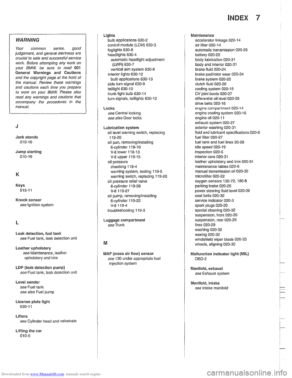
INDEX 7
WARNING
Your common sense, good
judgement, and general alertness are
crucial to safe and successful service
work. Before
attempting any work on
your BMW, be sure to read 001
General Warnings and Cautions
and the copyright page at the front of
the manual. Review these warnings
and cautions each time you prepare
to
work on your BMW. Please also
read any warnings and
caulions that
accompany
/he procedures in the
manual.
Jack stands
010-16
Jump starting 010-19
Keys
515-1 1
Knock sensor
see Ignition system
Leak detection,
fuel tanlr
see Fuel tank, leak detection unit
Leather upholstery
see Maintenance, leather
upholstery and trim
LDP
(leak detection pump)
see Fuel
tanir, leal( detection unit
Level sender
see Fuel tank
see also Fuel pump
License
plate iight
630-1 1
Lifters see Cylinder head and vaivetrain
Lifting the car
010-5 Lights
bulb applications
630-2
control module (LCM) 630-3
foglights 630-8 headiighls 630-4
automatic headlight adjustment
(LWR)
630-7
vertical aim system 630-8 interior lights 630-12
bulb applications 630-13
side turn signal 630-9
taillight 630.10 trunk light bulb 630-14
turn signals, taillights 630-12
LOClCS see Central loci(ing
see also Door loclrs
Lubrication system
oil
level warning switch, replacing
119-20
oil pan, removinglinstalling
6-cylinder 119-10
V-E lower 119-13 V-8 upper 119-15
oil pressure
checiring 11
9-4
warning system, testing 119-5 warning switch, replacing 119-20
oil pressure
reliel valve
6-cylinder 119-26
V-8 11 9-27
oil pump, removinglinstalling
6-cylinder
119-22
V-8 1 19-4
troubieshooting 119-3
Luggage compartment
seeTrunk
MAF (mass air flow) sensor
see 130 under appropriate fuel
injection system Maintenance
accelerator linkage
020-14 air filter 020-14
automatic transmission 020-29
battery 020-22
body lubrication 020-31 body and interior 020-31
braire fluid 020-24
brake padlrotor wear 020-24
brake system 020-25 clutch fluid 020-26
cooling system 020-15
CV ioint boots 020-27
differential oil level 020-26
drive bells 020-16 engine comparlmenl 020-14
engine cooling system 020-16
engine oil 020-1 1 exhaust system 020-27
exterior washing 020-31
fluid and lubricant specifications 020-9
fuel lilter 020-27 fuel lanir and fuel lines 20-28
idle speed 020-19
inspection 020-5
interior care 020-31
lealher upholslery and trim 020-31
maintenance tables 020-6
manual transmission oil 020-30
microiilter 020-22 oxygen sensors 130-72, 180-8
parlcing brake 020-25
power steering fluid level 020-20
seat belts
020-32 service indicator 020-3
spark plugs 020-20
special cleaning 020-32 suspension, front 020-29
suspension, rear 020-29
tires 020-29
washing
020-32
waxing 020-32 windshield wiper blade 020-33
wheels, aligning 020-30
Malfunction indicator iight (MIL)
OED-2
Manifold, exhaust
see Exhaust system
Manifold,
intake
see Intake maniiold
Page 998 of 1002
Downloaded from www.Manualslib.com manuals search engine
Manual transmission
applications 200-2. 230-5
back-up light switch, replacing 230-6
gear ratios 230-6
gearshift
see Gearshiit
ID tag 200-2
fluid 020-1 0. 200-4 fluid service 230-6
oil seals
input shaft seal, replacing
230-17
output shalt seal, replacing 230-1 1
selector
shaft seal, replacing 230-8 pilot bearing 210-16
removallinstallation 230-19
see also Maintenance
Map light
see Lights, interior
Mass air flow
(MAF) sensor
see 130 under appropriate fuel
injection syslem
Master cylinder
see Brakes
see also Clutch, hydraulics
MDK
130-42
Microfilter see
NC, ventilation microfilter
see also Maintenance
Mirror see Exterior trim
Misfire see Ignition syslem, diagnosis
Motor mount
see Engine,
mounl
MRS (multiple restraint system)
see Airbag system (SRS)
Muffler
see Exhaust syslem
Neutral safety switch
see Automatic transmission, range
switch
OED II (on-board diagnostics)
OED-l
Oil change equipment 010-16
Oil level sensor
see Lubrication system
Oil pan
see Lubrication system
OH pressure
see Lubrication system
Oil pump
see Lubrication system
Oil service 020-1 1
On-Board Monitor
640-12
On-board diagnostics OED-1
Outside air temperature sensor
610-14
Outside door handle
see Door
loclc
Outside mirror switch
see Switches
Output
shaft oil seal
see Manual transmission, oil seals
Overheating
see Cooling system, troubleshooting
Overload protection
600-11
Oxygen sensors
130-72, 180-8
P codes OED-10
Panic mode operation
515-11
Parking brake
see Brakes
see also Maintenance
Parts, buying
010-11
Pedal cluster switches
see Switches
Pedal position sensor (PWG)
6-cvlinder
enqine
V-8 engine (M62 TU) 130-68
Pitman arm
see Steering
Power steering
see Steering
Power steering
fluid
see Maintenance
Power window switch
512-3 see also Switches
PWG see Pedal position sensor
(PWG)
Racic and pinion steering
see Steering
Radiator see Cooling system
Radiator cooling fan seeCooling system, cooling fan
see also Cooling system, electric fan
Radiator grill
see Exterior
trim
Radio
650-2 see also Antenna
see also Speakers
Rain sensor
611-6
Raising car safely
010-5
Readiness codes
OED-6
Rear door window
see Door window
Rear main seal
see Crankshalt oil seals
Rear parcel
sheif
513-16
Page 999 of 1002
Downloaded from www.Manualslib.com manuals search engine
INDEX 9
WARNING
Your common sense, good judgemenl, and general alerlness are
crucial lo seie end successful service
ivork. Beiore attempting any work on
your
BMW be sure to read 001
General Warnings and Cautions and llle copyright page at lhe iron1 of
the manual. Review Niese warnings
and caulions each lime you prepare
lo work on your BMW Please also
read any warnings and caulions lllal accompany the procedures in the
manual.
Rear suspension
ball joints
330-19
bushings 330-13
control arms
seesuspension arms, below
description
300-5
electronic height control (EHC)
330-44
ride height 300-14 ride height sensor 330-46
shoclr absorbers end springs 330-9
stabilizer bar 330-42
struts and springs 330-5 subframe 330.13
suspension arms 330-13
variations 330-4 wheel bearing, replacing 330-32
see also Maintenance
see also Drive axles
see also Final drive
Rear window (Sport Wagon)
see
Tailgate
Rear window defroster 610-17
Receiverldrter
see NC
Relay positions
see Electrical component tocations
table 610-3
Remote entry (FZV)
see Central locking
Reversing light switch
see
Baclc-up light switch
Ride height
300-14
Ride height sensor
see Rear suspension
Ring antenna
see EWS (electronic immobilizalion)
Rotor
see Brakes
Roundel see Exterior trim
Running tosses
(312-way) valve
see Fuel
tenlr
SCA (soft close)
seeTailgate, soft close
see also Trunk lid. soft close
Scan tools
OED-3
Seals gaskets and 010-9
see also Crankshaft seals
Seat front,
removing/instelling 520-10
memory system 520-4 rear 520-13
see also Seat belt
Seat beit front 720-4
rear 720-8
troubleshooting 7202
see also Maintenance
Secondary air injection
see 130 under appropriate
iuel
injection system
Selector shaft seat
see Manual transmission, oil
Seals
Self-adjusting ctulch (SAC)
see Clutch, variations
Service indicator see Maintenance
Shift interlock see Gearshift
Shift lever
see
Gearshift
Shift linkage see Gearshift
Shiftlock see Gearshilt
Shack absorber see Rear suspension
/ Side turn signal assembly
see Lights
Sill trim panel
411-10
Slave cylinder
see Clutch, lhydraulic
Steep mode
600-1 1
Soft close
(SCA) see Tailgate
see also
Trunk lid
Solenoid 121-23
Sound system
650-2
Spare parts kit
010-21
Spark plugs
see Maintenance
Speakers
650-4
Specifications, fluid
020-4
Sport wagon
400-4
Springs
see Front suspension
see also Rear suspension
SRS (supplemental restraint system)
see
Airbag system (SRS)
Stabilizer bar see Front suspension
see also Rear suspension
Starter see Battery, starter, alternator
Page 1001 of 1002
Downloaded from www.Manualslib.com manuals search engine
WARNING
Your common sense, good
judgement, and general alertness are
crucial to saie and
successiul sewice
work. Beiore attempting any work on
your BMW be sure to read 001
General Warnings and Cautions
and the copyright page
a1 the iront of
the manual. Review tliese warnings
and cautions each time you prepare
to work on your
BMW. Please also
read any warnings and
cautions that
accompany the procedures in the
manual.
Towing 010-20
Traction control
see Brakes, ABS, ASC or DSC
system
Traction strut
see Rear suspension, suspension
arms
Transmission fluid
200-4
see Maintenance
see also Automatic transmission
see also Manuai transmission
Transmission
fluid heat exchanger
see Cooling system
Transmission input shaft oil seat
see Manual transmission
Transmission lubricant
200-4 see also Automatic transmission
see also Manual
lransmission
Transmission output shafl oil seal
see Manual transmission
Transmission pilot bearing
replacing 210-16
Transmission service see Manual transmission, oil seals
Trim, interior
see interior trim
see also Steering, steering column
trim
Trunk lid
412-2 soft close (SCA) 515-13
see also Trunkltailgale loci(
see also Central iocl
tailgate loci( emergency release
400-5, 515-21 tailgatelrear window locl(ing 515-14
trunk lock 51 5-1 9
lrey positions 515-7
Turn signai assembly
see Switches
see also Lights
UIS see Interior protection
U-joint
see Driveshaft
Upholstery see Maintenance, leather upholstery
and trim Vacuum
booster
see Brakes
Valve guides
see Cylinder
head and valvetrain
Valve seals
see Cylinder head and valvetrain
Valve seats
see Cylinder head and valvetrain
Valves see Cylinder head and
vaivelrain
Valvetrain see Cylinder head and valvetrain
VANOS control unit,
removinglinstalling
M52 engine 117-14
M52 TU i M54 engine 117-36 double VANOS
function
117-34 timing chain service 113-46. 116-28
timing, adjusting
M52 engine 117-22
M52 TU l M54 engine 117-43
Vehicle identification number (VIN)
010-12
Ventilation microfilter
see
AIC
see also Maintenance
Viscous clutch see Cooling
system, cooling tan
Voitage and polarity
600-5
Voltage tests
see Electrical system, troubleshooting