Brake fluid BMW 540i 2000 E39 User Guide
[x] Cancel search | Manufacturer: BMW, Model Year: 2000, Model line: 540i, Model: BMW 540i 2000 E39Pages: 1002
Page 454 of 1002
Downloaded from www.Manualslib.com manuals search engine
-
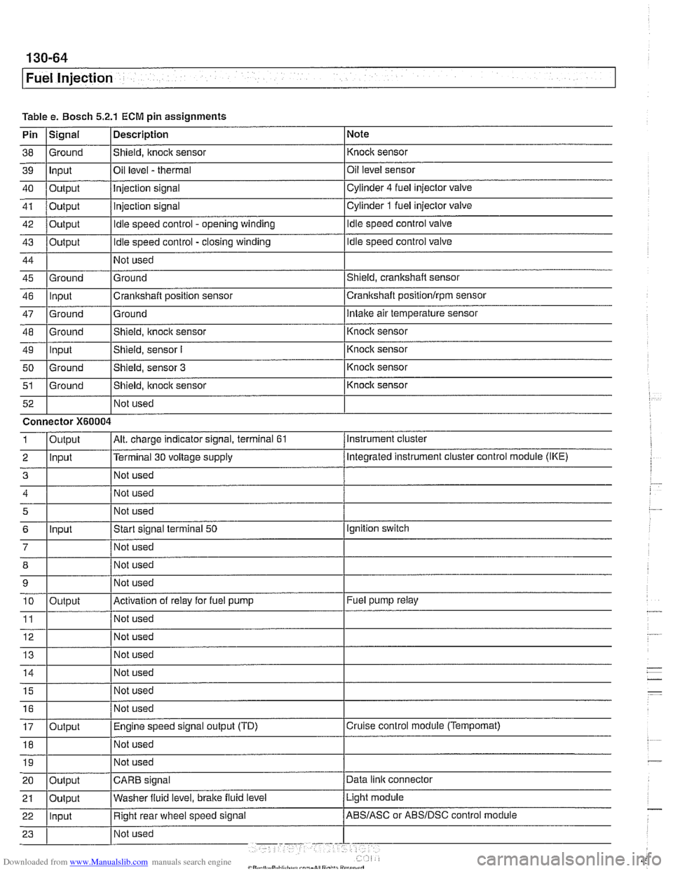
Fuel Injection
Table e. Bosch 5.2.1 ECM pin assignments
Pin
I~iqnal 1 Description 1 Note
I I I
46 llnput ICrankshaft position sensor Icrankshaft positionlrpm sensor
38
39
40
41
42
43
44
45 Ground Input
Output
Output
Output
Output
Ground
47
48
49
50
51
Not used
I Not used
52
Shield, knock sensor
Oil level
- thermal
Injection signal
injection signal
Idle speed control - opening winding
Idle speed control - closing winding
Not used
Ground
Ground
-- Ground Input
Ground
Ground Not used Knock sensor
Oil level sensor
Cylinder
4 fuel injector
valve
Cylinder
1 fuel injector valve
Idle speed control valve
Idle speed control valve
Shield, crankshaft sensor
5
6
7
12 Not used
Ground
Intake air temperature sensor
Connector
X60004
8
9 10
11
14 1 1 Not used I
Shield, knock sensor
Shield, sensor
I
Shield, sensor 3
Shield, itnock sensor
Input
- Knoclc sensor
Knock sensor
Knock sensor
Knock sensor
Instrument cluster
Output
2 llnput l~erminal 30 voltage supply /Megrated instrument cluster control module (IKE)
Alt. charge indicator signal, terminal 61 1
Not used
Start signal terminal
50
Not used
15
16
17
18
Output
Ignition switch
Not used
Not used
Activation of relay for fuel pump
Not used
19
Fuel pump relay
Output Not used
I I I 20 loutput ICARB signal /Data link connector
Not
used
Not used
Engine speed signal output (TD)
Not used
Light module
21
Cruise control module (Tempomat)
22 llnput I Right rear wheel speed signal /ABS/ASC or ABSIDSC control module
Oulput
Washer
fluid level,
brake fluid level
Page 546 of 1002
Downloaded from www.Manualslib.com manuals search engine
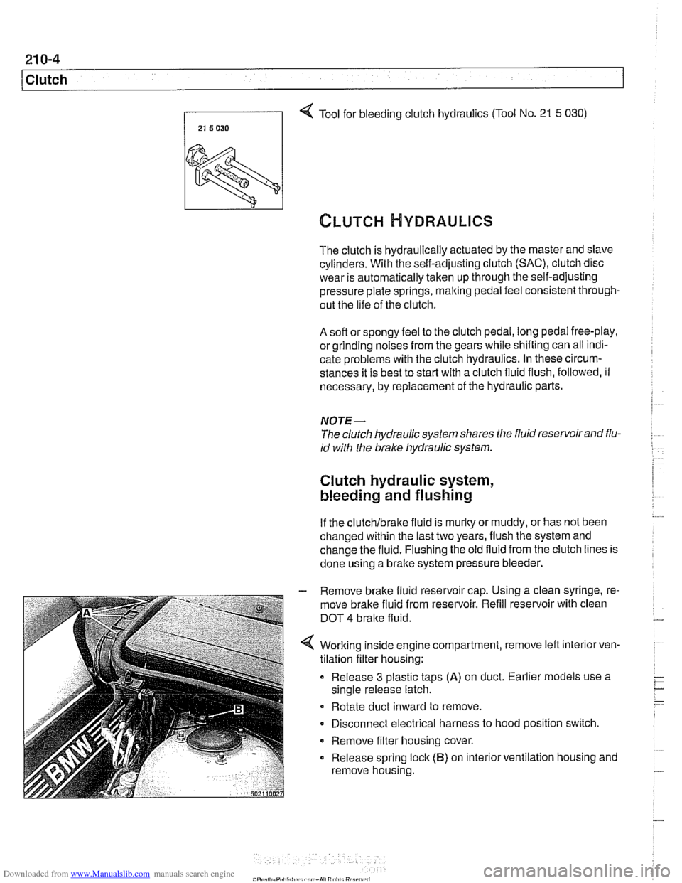
Tool for bleeding clutch hydraulics (Tool No. 21 5 030)
21 5 030 I
The clutch is hydraulically actuated by the master and slave
cylinders. With the self-adjusting clutch
(SAC), clutch disc
wear is automatically taken up through the self-adjusting
pressure plate springs, making pedal feel consistent through-
out the life of the clutch.
A soft or spongy feel to the clutch pedal, long pedal free-play,
or grinding noises
from the gears while shifting can all indi-
cate problems with the clutch hydraulics. In these circum-
stances it is best to
star? with a clutch fluid flush, followed, if
necessary, by replacement of the hydraulic parts.
NOTE-
The clutch hydraulic system shares the fluid reservoir and flu-
id with the brake hydraulic system.
Clutch hydraulic system,
bleeding and flushing
If the clutchlbralte fluid is murky or muddy, or has not been
changed within the last two years, flush the system and
change the fluid. Flushing the old fluid from the clutch lines is
done using a bralte system pressure bleeder.
- Remove brake fluid reservoir cap. Using a clean syringe, re-
move brake fluid from reservoir. Refill reservoir with clean
DOT
4 bralte fluid.
Worlting inside engine compartment, remove left
interiorven-
tilation filter housing:
Release 3 plastic taps
(A) on duct. Earlier models use a
single release latch.
Rotate duct inward to remove.
Disconnect electrical harness to hood position switch.
Remove filter housing cover.
Release spring lock
(B) on interior ventilation housing and
remove housing.
Page 547 of 1002
Downloaded from www.Manualslib.com manuals search engine
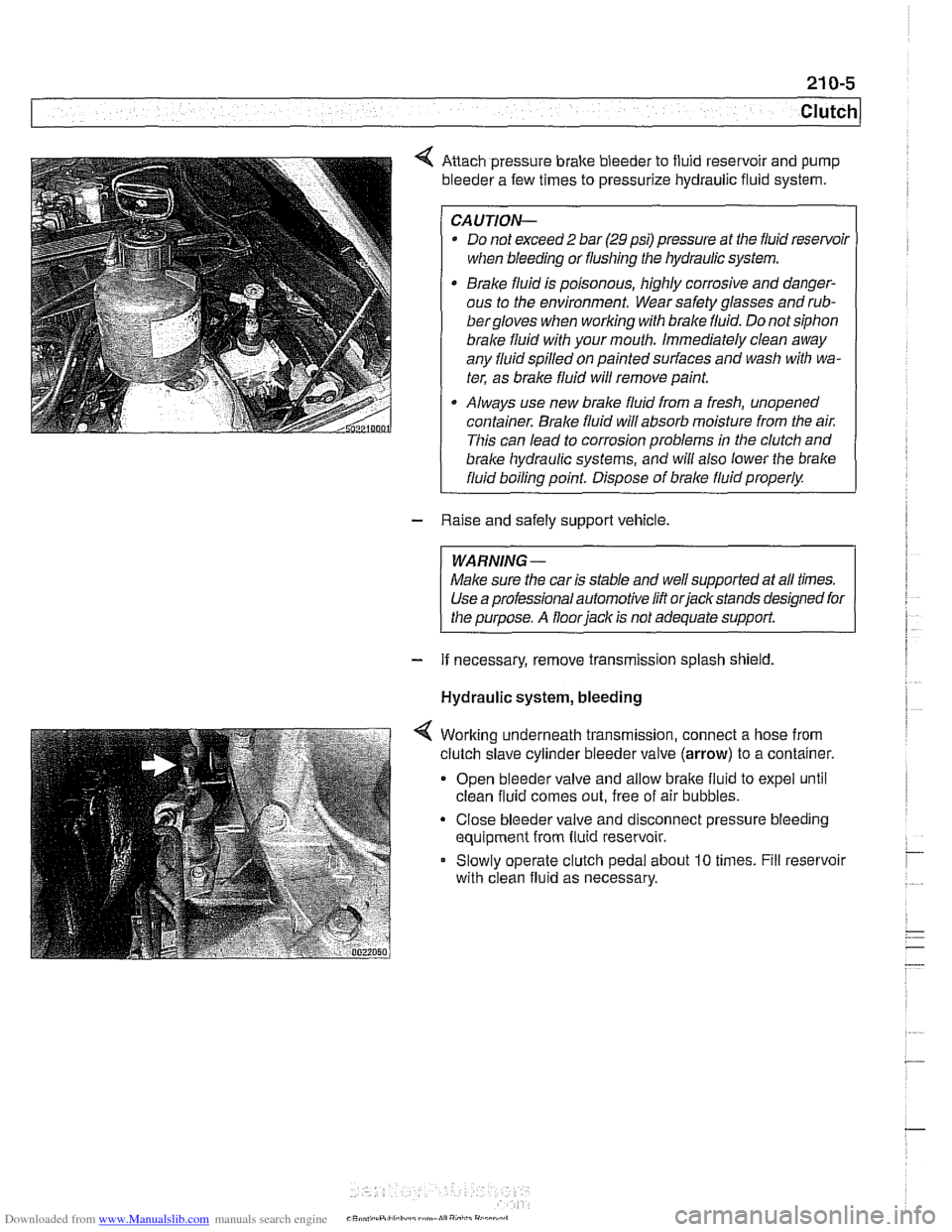
Anach pressure brake bleeder to fluid reservoir and pump
bleeder a few times to pressurize hydraulic fluid system.
CAUTION-
* Do not exceed 2 bar (29 psi) pressure at the fluid resenfoil
when bleeding or flushing the hydraulic system.
Brake fluid is poisonous, highly corrosive and danger-
ous to the environment. Wear safety glasses and
rub-
bergloves when working with brake fluid. Do not siphon
brale fluid with your mouth. Immediately clean away
any fluid spilled on painted surfaces and wash with wa-
ter, as brale fluid will remove paint.
Always use new brake fluid from a fresh, unopened
container.
Brake fluid will absorb moisture from the air.
This can lead to corrosion problems in the clutch and
brake hydraulic systems, ;nd will also lower the brake
fluid boiling point. Dispose of brale fluid properly.
- Raise and safely support vehicle.
WARNING-
Make sure the car is stable and well supported at all times.
Use a professional automotive lift orjackstands designed for
the purpose. A floor
iack is not adequate support.
- If necessary, remove transmission splash shield.
Hydraulic system, bleeding
Worlting underneath transmission, connect a hose from
clutch slave cylinder bleeder valve
(arrow) to a container.
Open bleeder valve and allow bralte fluid to expel until
clean fluid comes out, free of air bubbles.
Close bleeder valve and disconnect pressure bleeding
equipment from fluid reservoir.
Slowly operate clutch pedal about
10 times. Fill reservoir
with clean fluid as necessary.
CR* .,,, .rP,ll,h.:I,,~,~mn.lI","i,,i"
Page 548 of 1002
Downloaded from www.Manualslib.com manuals search engine
21 0-6
1 Clutch
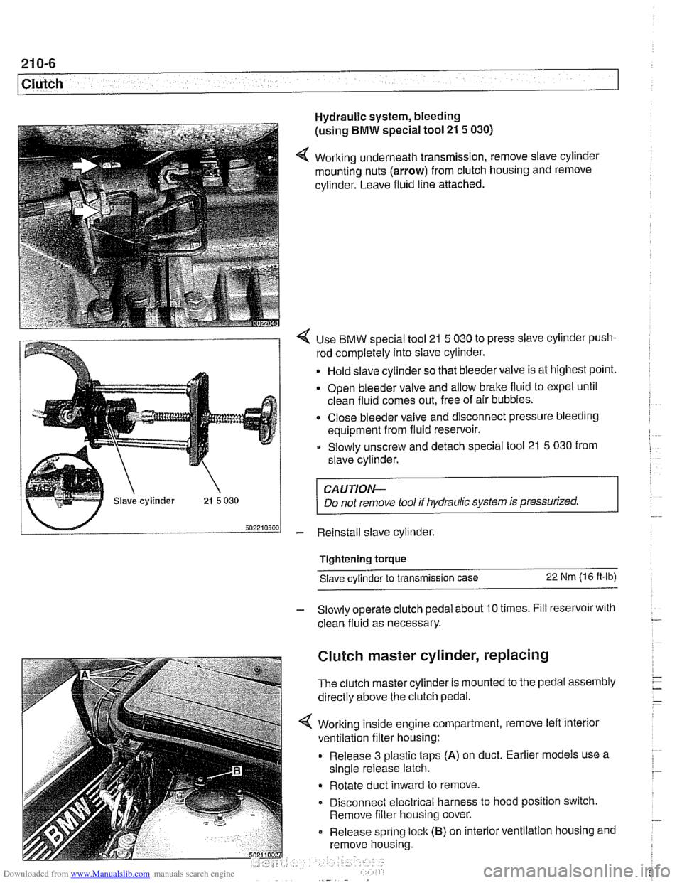
Hydraulic system, bleeding
(using
BMW special tool 21 5 030)
4 Working underneath transmission, remove slave cylinder
mounting nuts (arrow) from clutch housing and remove
cylinder. Leave fluid line attached.
4 Use BMW special tool 21 5 030 to press slave cylinder push-
rod completely into slave cylinder.
Hold slave cylinder so that bleeder valve is at highest point.
Open bleeder valve and allow brake fluid to expel until
clean fluid comes out, free of air bubbles.
* Close bleeder valve and disconnect pressure bleeding
equipment from fluid reservoir.
Slowly unscrew and detach special tool 21
5 030 from
slave cylinder.
CAUTION-
Do not remove tool if hydraulic system is pressurized.
- Reinstall slave cylinder.
Tightening torque Slave cylinder to transmission case
22 Nm (1 6 ft-lb)
- Slowly operate clutch pedal about 10 times. Fill reservoir with
clean fluid as necessary.
Clutch master cylinder, replacing
The clutch master cylinder is mounted to the pedal assembly
directly above the clutch pedal.
Working inside engine compartment, remove left interior
ventilation filter housing:
Release 3 plastic taps
(A) on duct. Earlier models use a
single release latch.
Rotate duct inward to remove
Disconnect electrical harness to hood position switch.
Remove filter housing cover.
Release spring
loclc (B) on interior ventilation housing and
remove housing.
Page 549 of 1002
Downloaded from www.Manualslib.com manuals search engine
21 0-7
Clutch
- Remove brake fluid reservoir cap. Using a clean syringe.
remove brake fluid from reservoir to below level of clutch
hydraulic supply hose.
- Detach clutch hydraulic supply hose from brake fluid reser-
voir. Plug reservoir outlet and hose.
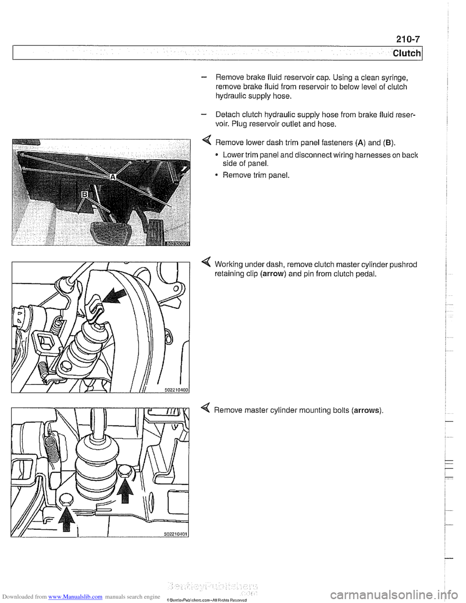
4 Remove lower dash trim panel fasteners (A) and (B).
Lower trim panel and disconnect wiring harnesses on back
side of panel.
Remove trim panel.
4 Working under dash, remove clutch master cylinder pushrod
retaining clip (arrow) and pin from clutch pedal.
4 Remove master cylinder mounting bolts (arrows)
Page 550 of 1002
Downloaded from www.Manualslib.com manuals search engine
21 0-8
Clutch
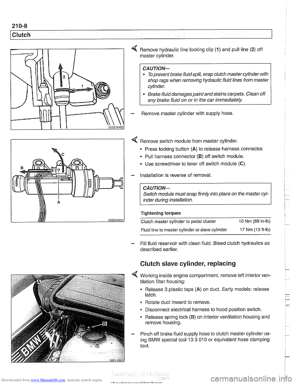
4 Remove hydraulic line locking clip (1) and pull line (2) off
master cylinder.
CAUTION-
. To prevent brake fluidspill, wrap clutch master cylinder with
shop rags when removing hydraulic fluid lines from master
cylinder.
* Brake fluid damages paint andstains carpets. Clean off
any brake fluid on or
in the car immediately.
- Remove master cylinder with supply hose
4 Remove switch module from master cylinder.
Press locking button
(A) to release harness connector.
Pull harness connector
(8) off switch module.
Use screwdriver to lever
off switch module (C).
- Installation is reverse of removal.
CA UTlON-
Switch module must snap firmly into place on the master cyl-
inder during installation.
Tightening torques
Clutch master cylinder to pedal cluster
10 Nm (89 in-lb)
Fluid line
to master cylinder or slave cylinder 17 Nm (13 ft-lb)
- Fill fluid reservoir with clean fluid. Bleed clutch hydraulics as
described earlier.
Clutch slave cylinder, replacing
4 Working inside engine compartment, remove left interiorven-
tilation filter housing:
Release
3 plastic taps (A) on duct. Early models: release
latch.
Rotate duct inward to remove.
Disconnect electrical harness to hood position switch.
Release spring lock (B) on interior ventilation housing and
remove housing.
- Pinch off brake fluid supply hose to clutch master cylinder us-
ing BMW special tool
13 3 01 0 or equivalent hose clamping
tool.
Page 590 of 1002
Downloaded from www.Manualslib.com manuals search engine
240-6
I Automatic Transmission Automatic transmission fluid (ATF)
The E39 automatic transmission is filled with either Dexron Ill
ATF or Texaco 80728, a life time oil.
CA UTIOI\C
Use only the transmission fluid that is approved for use by
BMW All other fluids will cause non warrantable transmis-
I sion damage.
Mixing different types of transmission fluids will lead to
transmission failure.
NOTE-
The type of transmission lubricant used can be found on a
stickeron the transmission pan. Dexron
111ATF (blacksticker)
reads "ATF-Oil': Special life time oil (green sticker) reads
'Life-Time Oil': If in doubt, consult an authorized
BMW dealer
for alternate fluid use and current information regarding
transmission operating fluids.
ATF level, checking
Check ATF level if there is evidence of a leak, a complaint re-
lated to fluid level or afler transmission repairs.
The automatic transmission is not equipped with a dipstick.
Checking the ATF level requires that the transmission be at
operating temperature during the checking procedure.
NOTE-
Vehicle must be level throughout tests
- Drive vehicle to warm up ATF to operating temperature.
- Connect BMW diagnostic scan tool DiSplus, MoDiC, GTI or
equivalent to determine transmission oil temperature.
ATF level checking
Fluid temperature
30' - 50°C (85' - 120" F)
- With engine running, switch on air conditioning to increase
engine idle speed.
- Apply parking brake.
- While applying foot brake firmly move gear shift selector
lever through
all gear positions, pausing in each gear briefly.
Page 632 of 1002
Downloaded from www.Manualslib.com manuals search engine
300-1 2
I Sus~ension, Steerincl and Brakes - General
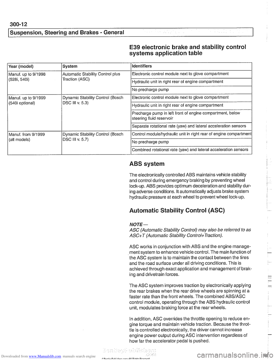
E39 electronic brake and stability control
systems application table
(528i, 54bi) Traction (ASC) I Hydraulic unit in right rear of engine compartment 1
Identifiers
Year (model)
I No precharge pump 1
Manuf. up to 911998 l~utomatic Stability Control plus I Electronic control module next to glove compartment
System
Precharge pump in
lefl front of engine compartment, below
steering fluid reservoir
Separate rotational rate (yaw) and lateral acceleration sensors
I I
Combined rotational rate (yaw) and lateral acceleration sensors
Electronic control
module next to glove compartment
Hydraulic unit in right rear of engine compartment
Manuf. up to 911999
(540i optional)
I I
ABS system
Dynamic Stability Control (Bosch
DSC
Ill v. 5.3)
The electronically controlled
ABS maintains vehicle stability
and control during emergency braking by preventing wheel
lock-up.
ABS provides optimum deceleration and stability dur-
ing adverse conditions. It automatically adjusts brake system
hydraulic pressure at each wheel to prevent wheel lock-up.
Control
moduleihydraulic unit
in right rear of engine compartment
No precharge pump
Manuf. from
911999
(all models)
Automatic Stability Control (ASC)
Dynamic Stability Control (Boscli
DSC Ill v. 5.7)
NOJE-
ASC (Automatic Stability Control) may also be referred to as
ASCiT (Automatic Stability ControkTraction).
ASC works in conjunction with ABS and the engine manage-
ment system to enhance vehicle control. The main function of
the
ASC system is to maintain the contact between the tires
and the road surface under all driving conditions. This is
achieved through exact application and management of brak-
ing and drivetrain forces.
The
ASC system improves traction by electronically applying
the rear brakes when the rear drive wheels are spinning at a
faster rate than the front wheels. The combined
ABSIASC
control module, operating through the ABS hydraulic control
unit, modulates braking force at the rear wheels.
In addition,
ASC overrides the throttle opening to reduce en-
gine torque and maintain vehicle traction. Because the throt-
tle is controlled electronically, the driver cannot increase
engine power output during
ASC intervention regardless of
how far the accelerator pedal is pushed.
Page 648 of 1002
Downloaded from www.Manualslib.com manuals search engine
/~ront Susaension
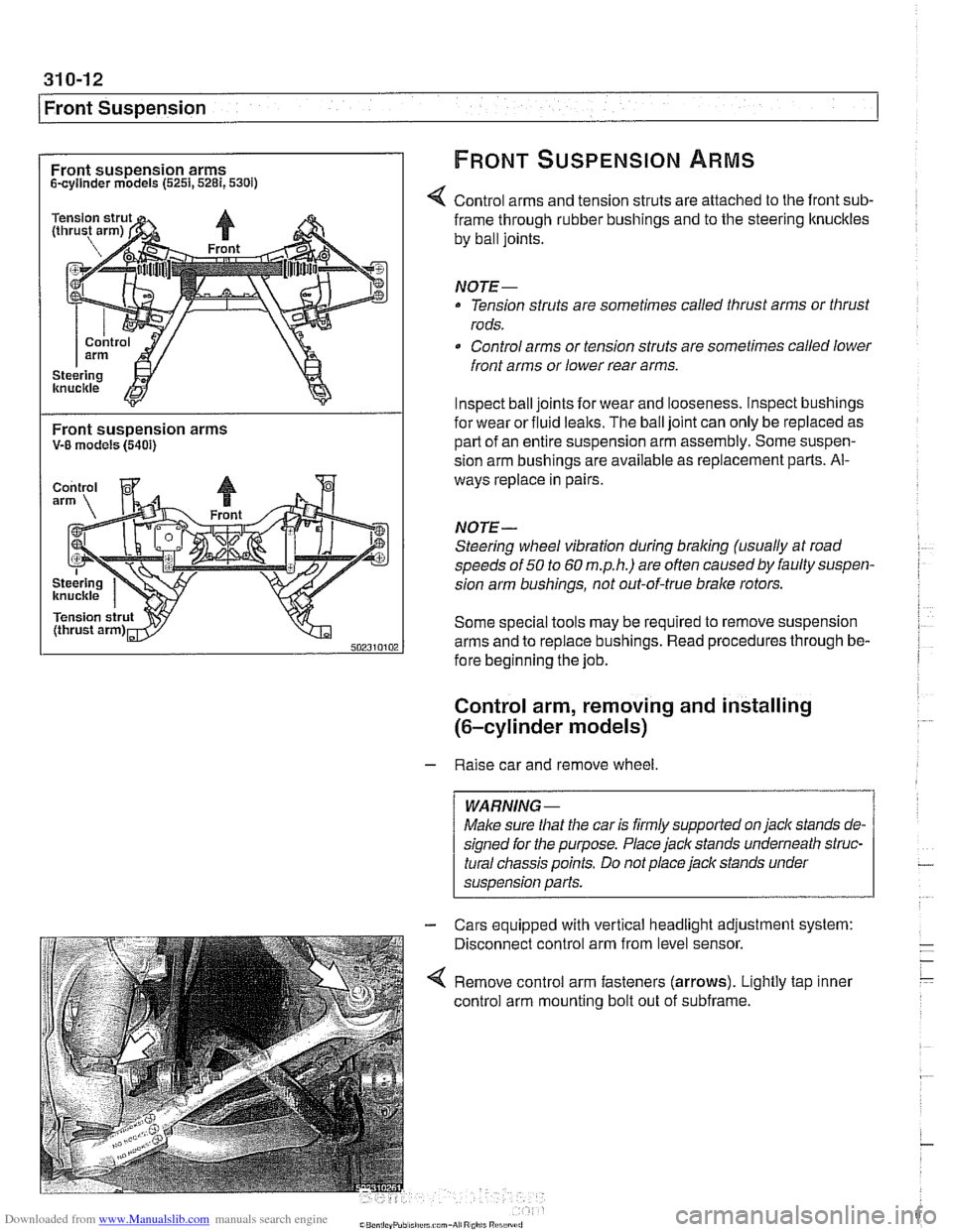
Front suspension arms FRONT SUSPENSION ARMS
Scyllnder models (5251,5281,530i)
Control arms and tension struts are attached to the front sub-
Front suspension arms V-8 models (5401)
frame through rubber bushings and to the steering ltnuckles
by ball joints.
NOTE-
Tension struts are sometimes called thrust arms or thrust
rods.
Control arms or tension struts are sometimes called lower
front arms or lower rear arms.
Inspect ball joints for wear and looseness. lnspect bushings
for wear or fluid
lealts. The ball joint can only be replaced as
part of an entire suspension arm assembly. Some suspen-
sion arm
bushinas are available as re~lacement Darts. Al-
ways replace in pairs
NOTE-
Steering wheel vibration during braking (usually at road
speeds of
50 to 60 m.p.h.) are often causedby faulty suspen-
sion arm bushings, not out-of-true brake rotors.
Some special tools may be required to remove suspension
arms and to replace bushings. Read procedures through be-
fore beginning the job.
Control arm, removing and installing
(6-cylinder models)
- Raise car and remove wheel
Male sure
that the car is firmly supported on jack stands de-
signed for the purpose. Place jack stands underneath struc-
tural chassis points. Do not place jack stands under
suspension
parfs.
Cars equipped with vertical headlight adjustment system:
Disconnect control arm from level sensor.
Remove control arm fasteners (arrows). Lightly tap inner
control arm mounting bolt out of subframe.
Page 707 of 1002
Downloaded from www.Manualslib.com manuals search engine
330-1 1
Rear Suspension
Coil spring, removing and installing
Raise car and remove rear wheels.
WARNING-
Make sure the car is firmly supported on jack stands de-
signed for the purpose. Place jack stands underneath struc-
tural chassis points. Do not place jack stands under
suspension parts.
- Remove brake caliper and brake disc. Hang brake caliper
aside with stiff wire. Do not disconnect
bralte fluid hose. See
340 Brakes.
- Remove exhaust system. See 180 Exhaust System.
- Disconnect driveshafl from final drive. See 260 Driveshaft.
- Detach parking bralte cables from mounting bracltets on sub-
frame.
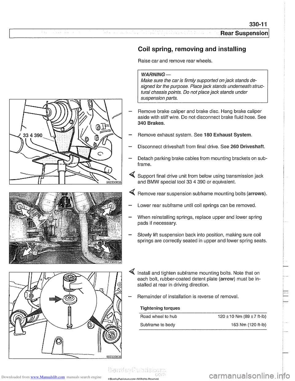
< Support final drive unit from below using transmission jack
and
BMW special tool 33 4 390 or equivalent.
Remove rear suspension
subframe mounting bolts (arrows).
Lower rear
subframe until coil springs can be removed.
When reinstalling springs, replace upper and lower spring
pads if necessary.
Slowly lift suspension
back into position, making sure coil
springs are correctly seated in upper and lower spring seats.
Install and tighten
subframe mounting bolts. Note that on
each bolt, rubber-coated detent plate (arrow) must be in-
stalled at rear in driving direction
- Remainder of installation is reverse of removal
Tightening torques Road wheel
to hub 12OilO Nm (89i-7 ft-lb)
Subframe to body 163 Nm (120 ft-lb)