jack points BMW 540i 2000 E39 Workshop Manual
[x] Cancel search | Manufacturer: BMW, Model Year: 2000, Model line: 540i, Model: BMW 540i 2000 E39Pages: 1002
Page 15 of 1002
Downloaded from www.Manualslib.com manuals search engine
General
Much of the necessary maintenance and minor repairthat an
automobile will need can be done with ordinary tools. Below
you'll find important information on how to work safely, a dis-
cussion of what tools will be needed and how to use them.
Safety
Although an automobile presents many hazards, common
sense and good equipment can help ensure safety. Many ac-
cidents happen because of carelessness. Pay attention and
stick to the safety rules in this manual.
Lifting the car
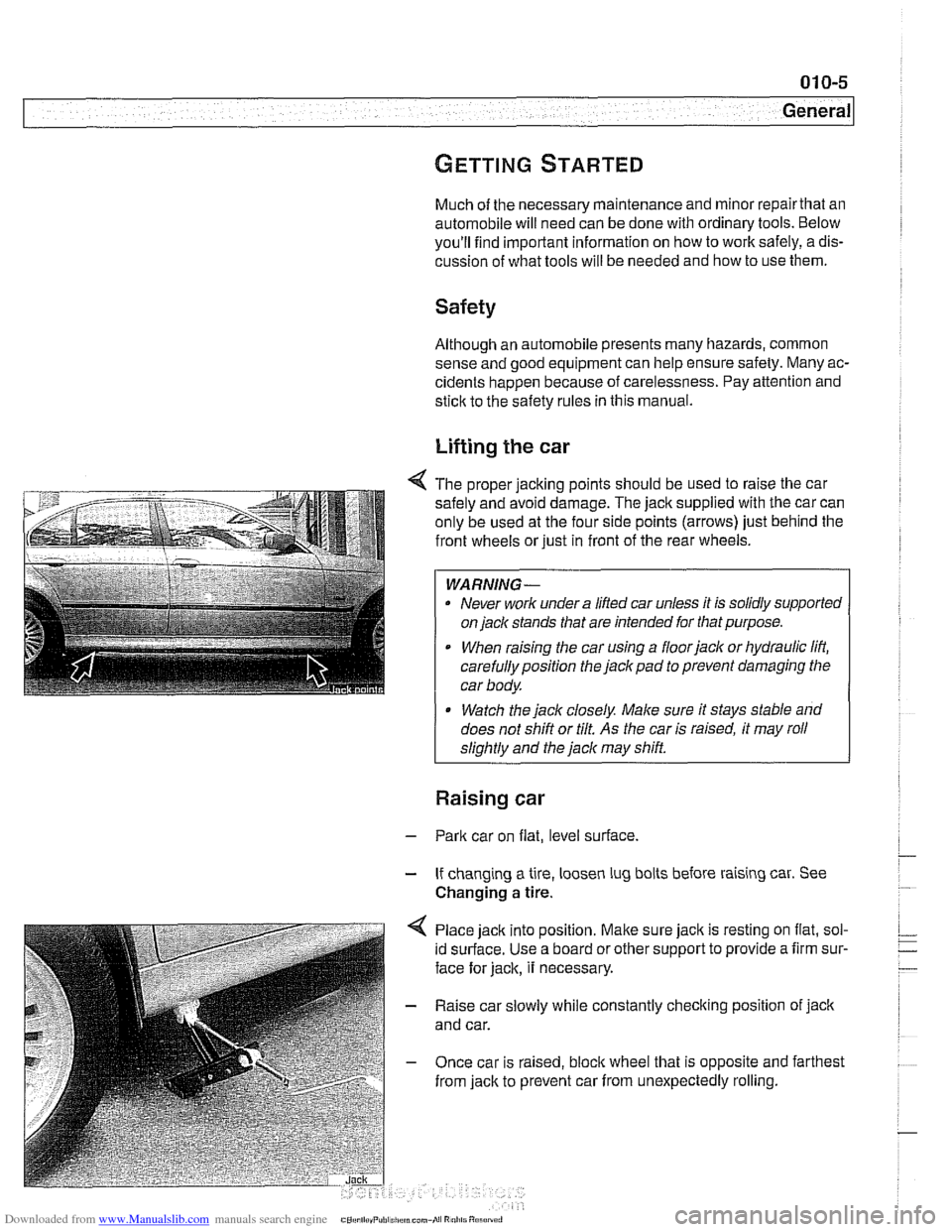
4 The proper jacking points should be used to raise the car
safely and avoid damage. The
jack supplied with the car can
only be used at the four side points (arrows) just behind the
front wheels or just in front of the rear wheels.
WARNING-
. Never work under a lifted car unless it is solidly supported
on
jack stands that are intended for that purpose.
When raising the car using a floorjack or hydraulic lift,
carefully position the jack pad to prevent damaging the
car body.
* Watch the jack closely. Male sure it stays stable and
does not shift or tilt.
As the car is raised, it may roll
sliahtlv and the
jack mav shift.
Raising car
- Park car on flat, level surface.
- If changing a tire, loosen lug bolts before raising car. See
Changing
a tire.
Place jack into position.
Malte sure jack is resting on flat, sol-
id surface. Use a board or other support to provide a firm sur-
face for jack, it necessary.
- Raise car slowly while constantly checking position of jack
and car.
- Once car is raised, bloclc wheel that is opposite and farthest
from jack to prevent car from unexpectedly rolling.
Page 641 of 1002
Downloaded from www.Manualslib.com manuals search engine
31 0-5
Front ~uspensionl
Front strut assembly, removing and
installing
- Raise car and remove front wheel.
WARNING-
Make sure that the car is firmly supported on jack stands de-
signed for the purpose. Place jack stands underneath struc-
tural chassis points.
Do not place jack stands under
suspension
parts.
- Unbolt bralte caliper assembly, lkeeping bralte hose connect-
ed. Secure brake caliper to body with wire. Do not let it hang
from brake hose. See
340 Brakes.
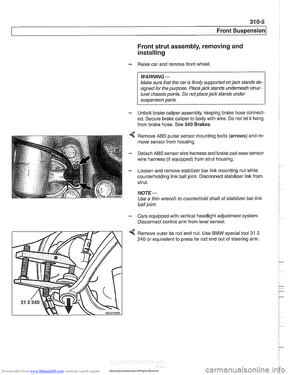
Remove ABS pulse sensor mounting bolts (arrows) and re-
move sensor from housing.
Detach ABS sensor wire harness and bralte pad wear sensor
wire harness (if equipped) from strut housing.
Loosen and remove stabilizer bar link mounting nut while
counterholding
link ball joint. Disconnect stabilizer link from
strut.
NOTE-
Use a thin wrench to counterhold shaft of stabilizer bar link
ball joint.
- Cars equipped with vertical headlight adjustment system:
Disconnect control arm from level sensor.
4 Remove outer tie rod end nut. Use BMW special tool 31 2
240 or equivalent to press tie rod end out of steering arm.
Page 648 of 1002
Downloaded from www.Manualslib.com manuals search engine
/~ront Susaension
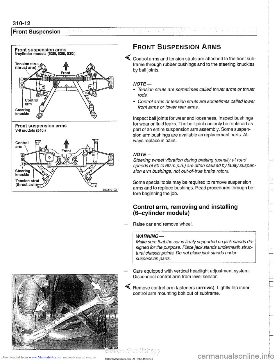
Front suspension arms FRONT SUSPENSION ARMS
Scyllnder models (5251,5281,530i)
Control arms and tension struts are attached to the front sub-
Front suspension arms V-8 models (5401)
frame through rubber bushings and to the steering ltnuckles
by ball joints.
NOTE-
Tension struts are sometimes called thrust arms or thrust
rods.
Control arms or tension struts are sometimes called lower
front arms or lower rear arms.
Inspect ball joints for wear and looseness. lnspect bushings
for wear or fluid
lealts. The ball joint can only be replaced as
part of an entire suspension arm assembly. Some suspen-
sion arm
bushinas are available as re~lacement Darts. Al-
ways replace in pairs
NOTE-
Steering wheel vibration during braking (usually at road
speeds of
50 to 60 m.p.h.) are often causedby faulty suspen-
sion arm bushings, not out-of-true brake rotors.
Some special tools may be required to remove suspension
arms and to replace bushings. Read procedures through be-
fore beginning the job.
Control arm, removing and installing
(6-cylinder models)
- Raise car and remove wheel
Male sure
that the car is firmly supported on jack stands de-
signed for the purpose. Place jack stands underneath struc-
tural chassis points. Do not place jack stands under
suspension
parfs.
Cars equipped with vertical headlight adjustment system:
Disconnect control arm from level sensor.
Remove control arm fasteners (arrows). Lightly tap inner
control arm mounting bolt out of subframe.
Page 649 of 1002
Downloaded from www.Manualslib.com manuals search engine
Front Suspension
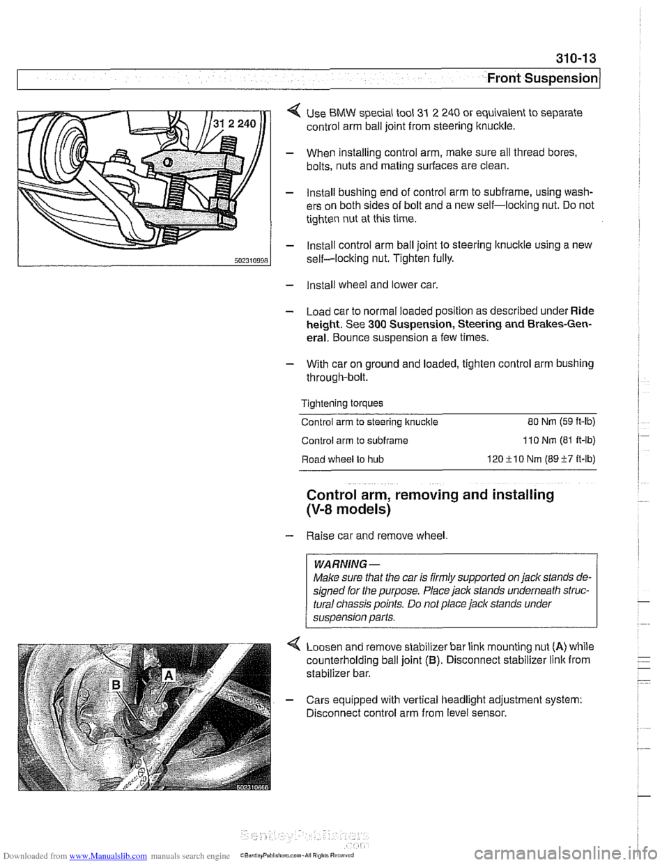
< Use BMW special tool 31 2 240 or equivalent to separate
control arm ball joint from steering ltnuckle.
- When installing control arm, make sure all thread bores.
bolts, nuts and mating surfaces are clean.
- Install bushing end of control arm to subframe, using wash-
ers on both sides of bolt and a new self-locking nut. Do not
tighten nut at this time.
- Install control arm ball joint to steering lknucltle using a new
self-locking nut. Tighten fully.
- Install wheel and lower car.
- Load car to normal loaded position as described under Ride
height. See
300 Suspension, Steering and Brakes-Gen-
eral. Bounce suspension a few times.
- With car on ground and loaded, tighten control arm bushing
through-bolt.
Tightening torques
Control arm to steering ltnuckle
80 Nm (59 ft-lb)
Control arm to subframe 110 Nm (81 It-lb)
Road wheel to hub 120ilO Nm (8957 it-lb)
Control arm, removing and installing
(V-8 models)
- Raise car and remove wheel
WARNING-
Make sure that the car is firmly supported on jack stands de-
signed for the purpose. Place jack stands underneath struc-
tural
cliassis points. Do not place jack stands under
suspension parts.
Loosen and remove stabilizer bar link mounting nut
(A) while
counterholding ball joint
(B). Disconnect stabilizer link from
stabilizer bar.
- Cars equipped with vertical headlight adjustment system:
Disconnect control arm from level sensor.
Page 652 of 1002
Downloaded from www.Manualslib.com manuals search engine
I Front Suspension
Tension strut, removing
and installing
- Raise car and remove wheel.
WARNING-
Make sure that the car is firmly supported on jack stands de-
signed for the purpose. Place jack stands underneath struc-
tural chassis points. Do not place
jack stands under
suspension parts.
- Remove engine splash shield
6-cylinder models: Remove
brake cooling duct.
V-8 models: Detach stabilizer bar from front subframe.
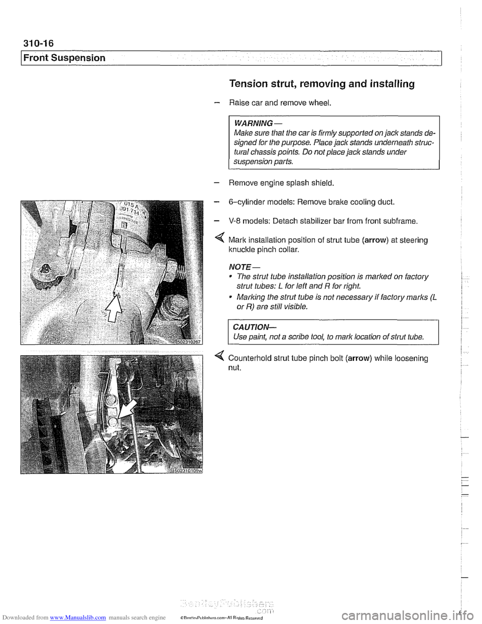
Mark installation position of strut tube (arrow) at steering
ltnuckle pinch collar.
NOJE-
* The strut tube installation position is marlted on factory
strut tubes:
L for left and R for right.
* Marlting the strut tube is not necessary if factory marks (L
or R) are still visible.
CAUJION-
Use paint, not a scribe tool, to mark location of strut tube. 1
4 Counterhold strut tube pinch bolt (arrow) while loosening
nut.
Page 654 of 1002
Downloaded from www.Manualslib.com manuals search engine
31 0-1 8
I~ront Suspension Tension strut bushing, replacing
- Raise car and remove wheel.
WARNING-
Make sure that the caris firmly supported on jack stands de-
signed for the purpose. Place jack stands underneath struc-
tural chassis points. Do
not place jack stands under
suspension parts.
- Remove tension strut from car as described earlier.
- Using a service press and appropriate press tools (BMW
special tools 31 2 26112621263 or equivalent), press bushing
out of tension strut.
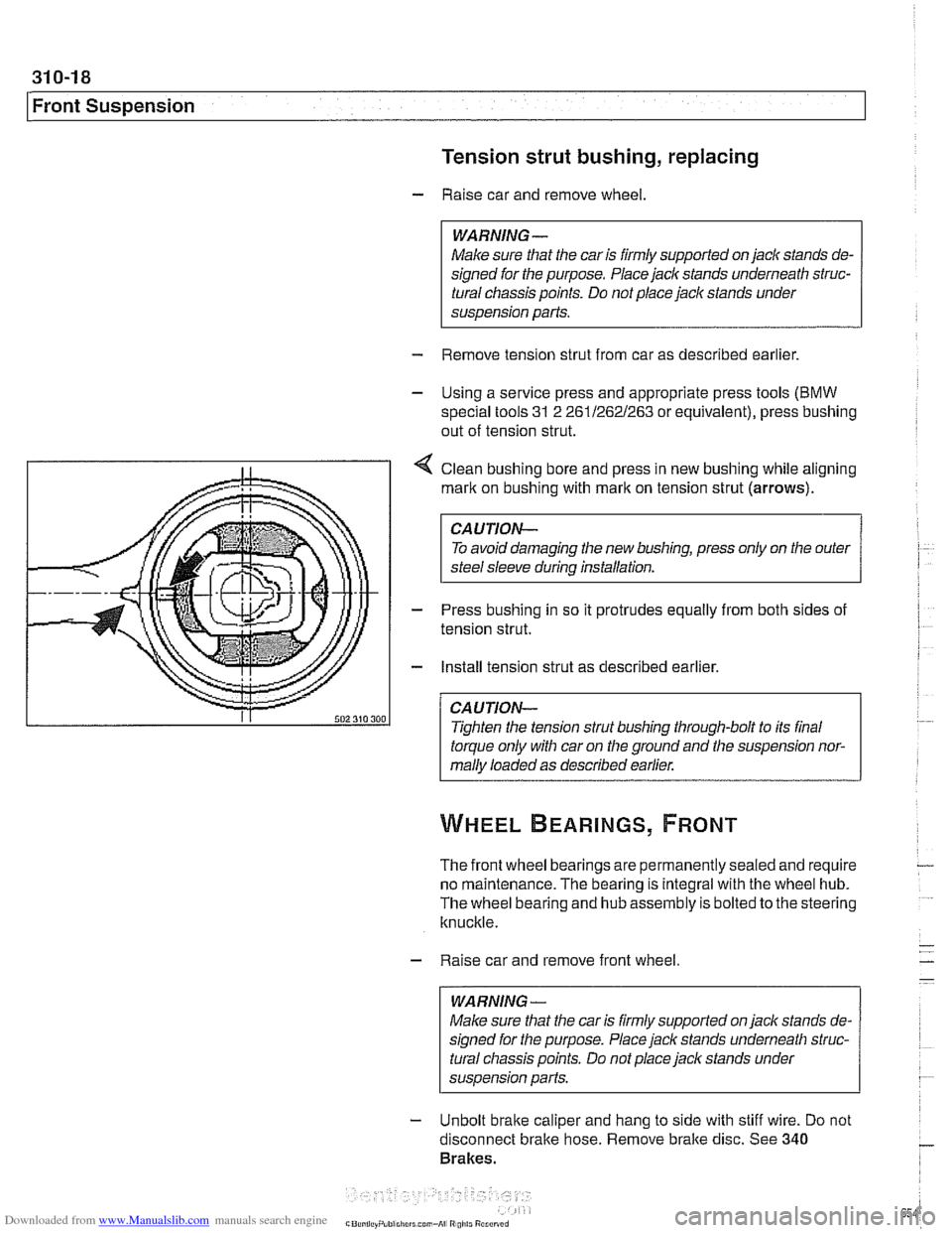
4 Clean bushing bore and press in new bushing while aligning
mark on bushing with
rnarlt on tension strut (arrows).
CAUTION-
To avoid damaging the new bushing, press only on the outer
steel sleeve during installation.
- Press bushing in so it protrudes equally from both sides of
tension strut.
- Install tension strut as described earlier.
CAUTION-
Tighten the tension strut bushing through-bolt to its final
torque only with car on the ground and the suspension nor-
mally loaded as described earlier.
The front wheel bearings are permanently sealed and require
no maintenance. The bearing is integral with the wheel hub.
The wheel bearing and hub assembly is bolted to the steering
knuckle.
- Raise car and remove front wheel
WARNING-
Make sure that the car is firmly supported on jack stands de-
signed for the purpose. Place jack stands underneath struc-
tural chassis points. Do not place
jack stands under
susoension Darts.
- Unbolt brake caliper and hang to side with stiff wire. Do not
disconnect bralte hose. Remove bralte disc. See
340
Brakes.
Page 658 of 1002
Downloaded from www.Manualslib.com manuals search engine
31 0-22
I Front Suspension
Stabilizer bar, removing and installing
On E39 models the front stabilizer bar links attach to the strut
assemblies.
- Raise car and support safely.
Male sure that the car is firmly supported on jack stands de-
signed for the purpose. Place jack stands underneath struc-
tural chassis points. Do not place jaclc stands under
suspension parts.
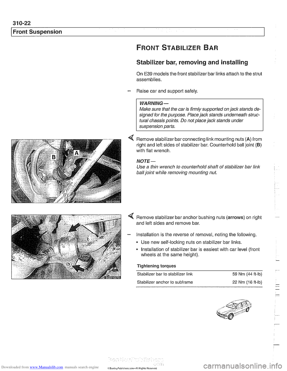
< Remove slaol zer bar connecring I nk rnounl ng nLts (A) from
r~glit and eft s~des of slaol lzer bar C~~nIerhol~ ball ]olnl (6)
with flat wrench
NOTE-
Use a thin wrench to counterhold shaft of stabilizer bar link
ball joint while removing mounting nut.
< Remove stabilizer bar anchor bushing nuts (arrows) on right
and left sides and remove bar.
- Installation is the reverse of removal, noting the following.
Use new self-locking nuts on stabilizer bar links.
Installation of stabilizer bar is easiest with car level (front
wheels at the same height).
Tightening torques Stabilizer bar to stabilizer link
59 Nm (44 ft-lb)
Stabilizer anchor to subframe 22 Nm (16 ft-lb)
Page 675 of 1002
Downloaded from www.Manualslib.com manuals search engine
Steering and Wheel Alignment
Power assist is provided by a belt-driven pump at the lower
left front of the engine. The power steering fluid reservoir is lo-
cated at the left side of the engine compartment.
Power steering pump, removing and
installing
When working with power steering components, absolute
cleanliness is needed to ensure proper operation of the hy-
- Empty power steering fluid reservoir using clean syringe. Do
not reuse fluid.
- Raise front of car. Remove splash shield from under engine.
WARNING-
Make sure the car is firmly supported on jack stands de-
signed for the purpose. Place jack stands beneath structural
chassis points. Do not place jack stands under suspension
Darts.
Remove drive belt from power steering pump. See
020 Main-
tenance.
Remove alternator cooling duct
Remove fluid hoses from pump. Plug openings in pump and
hose ends.
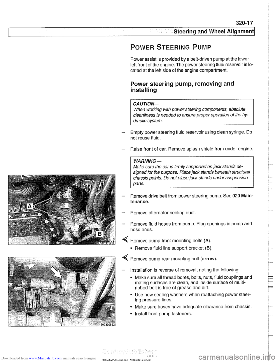
Remove pump front mounting bolts
(A).
Remove fluid line support bracket (B)
Remove pump rear mounting bolt (arrow)
- Installation is reverse of removal, noting the following:
Make sure all thread bores, bolts, nuts, fluid couplings and
mating
surfaces are clean, and inside surface of multi-
ribbed-belt is free of grease and dirt.
Use new sealing washers when reattaching power steer-
ing pressure lines.
Make sure hoses have adequate clearance from chassis.
Install front pump fasteners.
Page 677 of 1002
Downloaded from www.Manualslib.com manuals search engine
i Steering and Wheel Alignment
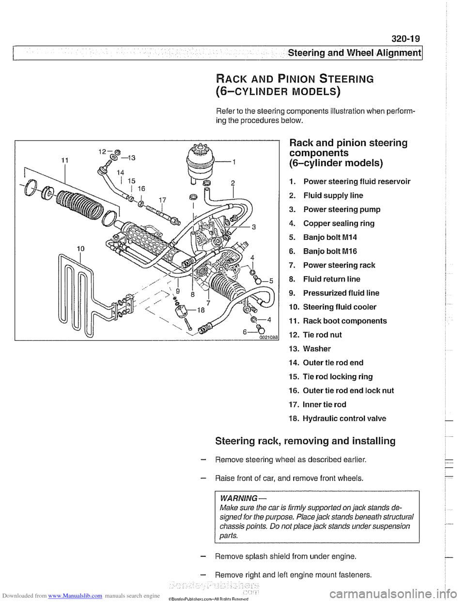
RACK AND PINION STEERING
(6-CYLINDER MODELS)
Refer to the steering components illustration when perform-
ing the procedures below.
Rack and pinion steering
components
(6-cylinder models)
1. Power steering fluid reservoir
2. Fluid supply line
3. Power steering pump
4. Copper sealing ring
5. Banjo bolt MI4
6. Banjo bolt MI6
7. Power steering rack
8. Fluid return line
9. Pressurized fluid line
10. Steering fluid cooler
11. Rack boot components
12. Tie rod nut
13. Washer
14. Outer tie rod end
15. Tie rod locking ring
16. Outer tie rod end loclc nut
17. Inner tie rod
18. Hydraulic control valve
Steering rack, removing and installing
- Remove steering wheel as described earlier.
- Raise front of car, and remove front wheels.
WARNING -
Male sure the car is firmly supported on jack stands de-
signed for the purpose. Place jack stands beneath structural
chassis points. Do
not place jack stands under suspension
parts.
- Remove splash shield from under engine.
- Remove right and lefl engine mount fasteners
-" ., - , . ,
Page 683 of 1002
Downloaded from www.Manualslib.com manuals search engine
Steering and Wheel ~li~nrnentl
Steering gearbox, removing and installing
- Disconnect negative (-) battery cable. See 020 Mainte-
nance.
CAUTION-
Prior to disconnecting the battew read the battery discon-
nection cautions given in
001 General Cautions and
Warnings.
- Remove airbag unit from steering wheel. See 721 Airbag
System (SRS).
WARNING -
Improper handling of the airbag could cause serious injury
Store the
airbag with the horn pad facing up. If stored lacing
down, accidental deployment couldpropel it violently info the
air, causing
injuv
- Remove steering wheel as described earlier.
- Drain power steering system reservoir.
- Raise front of car.
WARNING -
Make sure the car is firmly supported on jack stands de-
signed for the purpose. Place jack stands beneath structural
chassis points. Do not place jack stands under suspension
Darts.
- Remove heat shield from left side of subframe.
- Remove fluid hoses from top of steering gearbox. Immedi-
ately plug all fluid openings.
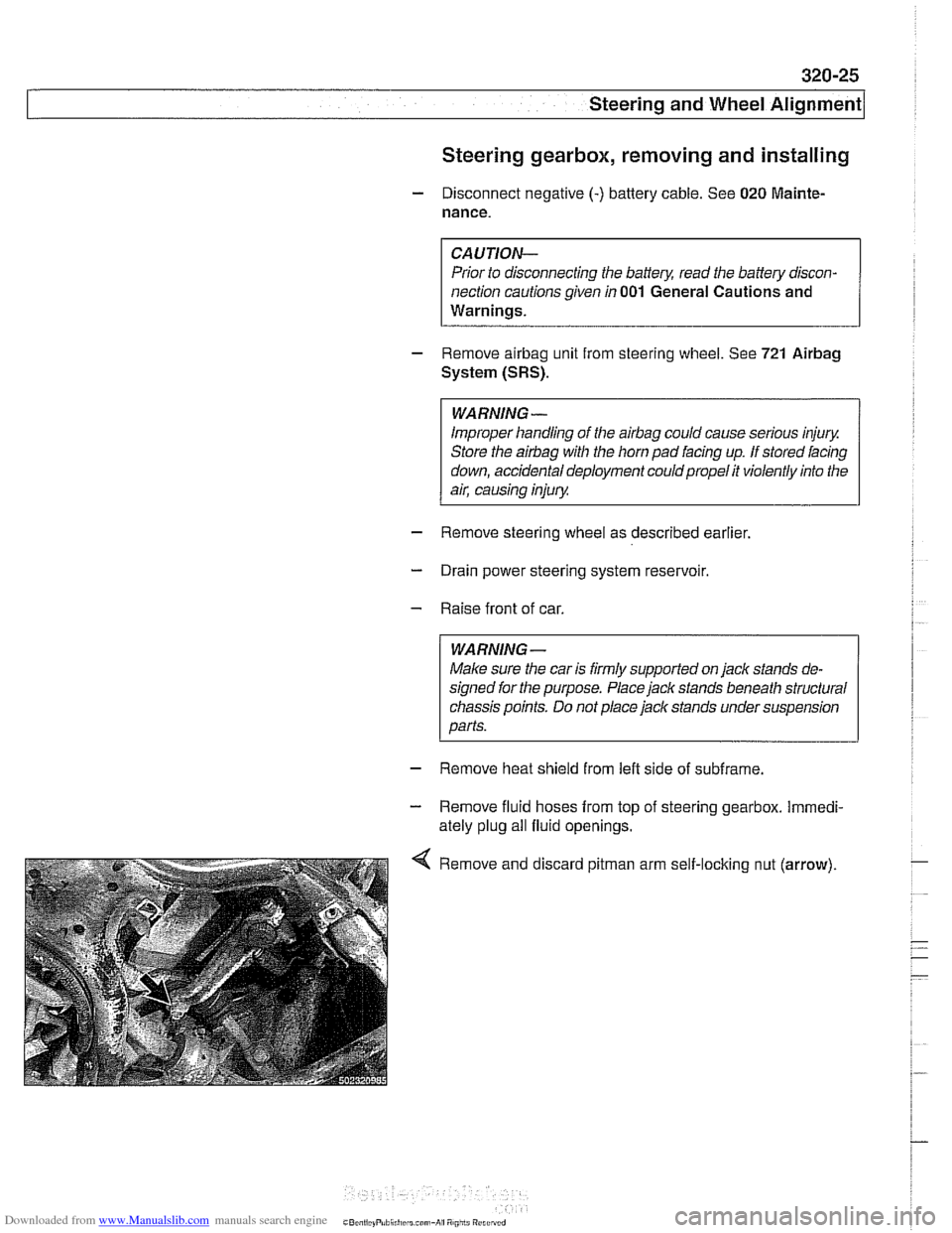
Remove and discard
pitman arm self-loclting nut (arrow).