seats BMW 540i 2000 E39 Workshop Manual
[x] Cancel search | Manufacturer: BMW, Model Year: 2000, Model line: 540i, Model: BMW 540i 2000 E39Pages: 1002
Page 3 of 1002
Downloaded from www.Manualslib.com manuals search engine
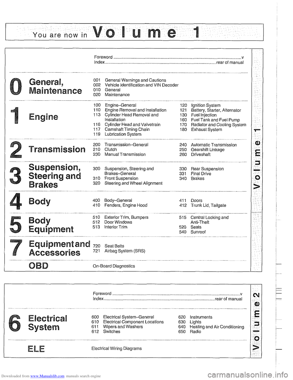
YOU are now in Volume I
I
Foreword ................... .. ........................................................................\
.......... v
Index
........................ .. ................................................................ rear of manual
General, 001 General Warnings and Cautions 002 Vehicle Identification and VIN Decoder
Maintenance OiO 020 Maintenance
Engine
100 Engine-General 110 Engine Removal and Installation
113 Cylinder Head Removal and
Installation
116 Cyiinder Head and Valvetrain 117 Camshaft Timing Chain
119 Lubrication System
200 Transmission-General
2 Transmission 210 clutch 230 ManualTransmission
I20 Ignition System
121 Battery, Starter, Alternator
130 Fuel Injection
160 Fuel Tank and Fuel Pump 170 Radiator and Cooling System
180 Exhaust System
240 Automatic Transmission
250 Gearshift Linkage 260 Driveshaft
Suspension, 300 Suspension, Steering and 330 Rear Suspension
Brakes-General 331 Final Drive
Steering and No Front Suspension 340 Brakes
320 Steering and Wheel Alignment
400 Body-General
410 Fenders, Engine Hood 411 Doors
412 Trunk Lid, Tailgate
510 Exterior Trim, Bumpers 512 Door Windows
Equipment 513 Interior Trim
7
Equipment and 720 seat Belts
Accessories 721 Airbag System (SRS)
OBD On-Board Diagnostics
. ............ ..
515 Central Lociting and
Anti-Theft
520 Seats 540 Sunroof
.................................................................... Foreword .............................. .. v
Index ................... .. ................................................................ rear of manual
Electrical
6 system
600 Electrical System-General 620 Instruments
610 Electrical Comoonent Locations 630 Liohts
611 wipers and washers 612 Switches eati in^ and Air Conditioning
Radio
. ........... ........ .........................
Electrical Wiring Diagrams
Page 177 of 1002
Downloaded from www.Manualslib.com manuals search engine
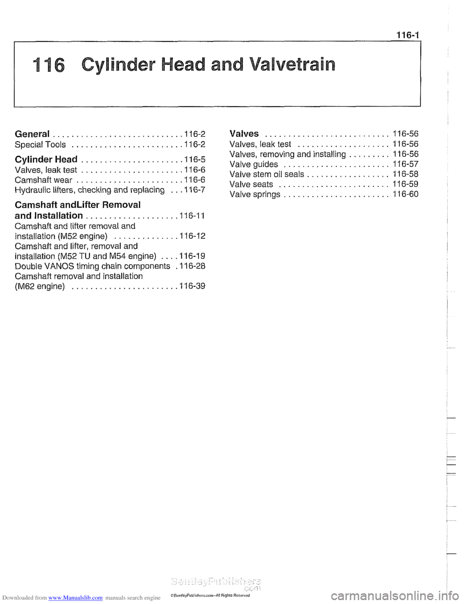
11 6 Cylinder Head and Valvetrain
........................... General ............................ 1 16-2 Valves 116-56
.................... Special Tools ........................ 11 6-2 Valves. leak test 11 6-56
......... Valves. removing and installing 11 6-56 Cylinder Head ..................... .I1 6.5 ....................... Valve guides 11 6-57
Valves. leak test ...................... 11 6-6
Valve stem oil seals .................. 11 6-58 ...... ..""""."""ll 6.6 Valveseats ........................ 116-59 Hydraulic lifters, checking and replacing .. .I1 6-7 Valve ....................... 6-60 . .
Camshaft andLifter Removal
and Installation
.................... 11 6-1 1
Camshaft and lifter removal and
installation
(M52 engine) ............. .I1 6.12
Camshaft and lifter. removal and
installation (M52
TU and M54 engine) .... 11 6-1 9
Double VANOS timing chain components
. 11 6-28
Camshaft removal and installation
(M62 engine)
....................... 11 6-39
Page 181 of 1002
Downloaded from www.Manualslib.com manuals search engine
11 6-5
I Cylinder Head and valvetrain1
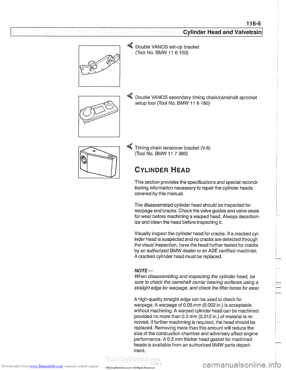
4 Timing chain tensioner bracket (V-8)
(Tool No. BMW
11 7 380)
CYLINDER HEAD
This section provides the specifications and special recondi-
tioning information necessary to repair the cylinder heads
covered by this manual.
The disassembled cylinder head should be inspected for
warpage and cracks. Check the valve guides and valve seats
for wear before machining a warped head. Always decarbon-
ize and clean the head before inspecting it.
Visually inspect the cylinder head for craclts.
If a cracked cyl-
inder head is suspected and no
craclts are detected through
the visual Inspection, have the head further tested for cracks
by an authorized BMW dealer or an ASE certified machinist.
A cracked cylinder head must be replaced.
NOJE-
When disassembling and inspecting the cylinder head, be
sure to
checlc the camshaft carrier bearing surfaces using a
straight edge for
warpage, and check the lifter bores for wear.
A high-quality straight edge can be used to
checlc for
warpage. A warpage of 0.05 mm (0.002 in.) is acceptable
without machining. A warped cylinder head can be machined
provided no more than 0.3
mm (0.012 in.) of material is re-
moved.
If further machining is required, the head should be
replaced. Removing more than this amount will reduce the
size of the combustion chamber and adversely affect engine
performance. A 0.3 mm
thicker head gasket for machined
heads is available from an authorized BMW parts depart-
ment.
Page 232 of 1002
Downloaded from www.Manualslib.com manuals search engine
1 16-56
Cylinder Head and Valvetrain
This section covers valve removal and reconditioning, includ-
ing valve guides, seats, springs, and valve stem oil seals.
Valves, leak test
To test the valves for leakage, the cylinder head must be dis-
assembled with camshafts and camshaft carriers removed.
With valve assemblies and spark plugs installed, place the
cylinder head on a workbench with the combustion chamber
facing upward. Fill each combustion chamber with a thin non-
flammable liquid. After fifteen minutes,
check the level of the
fluid. If the fluid level in any cylinder drops, that cylinder is not
sealing properly.
Valves, removing and installing
- Remove cylinder head as described in 113 Cylinder Head
Removal and Installation.
CAUTIOI\C
(M52 TU/M54 engines only) Do not let the hydraulic lifters
fall out as the camshaft carrier is removed. Special suction
cups are available from
BMW to hold the hydraulic lifters in
place during carrier removal.
* Hydraulic cam lifters should be stored m an uprfght po-
sition. If necessary, use a magnetic tool to
aidin remov-
al of the lifters.
- Remove valves using a valve spring compressor.
CAUTIOI\C
Label each valve assembly as it is removed so it can be in-
stalled in its original position.
-
- Remove and discard valve stem oil seals from valve guides.
See Valve stem oil seals later in this section.
- Valve installation is reverse of removal. Remove carbon de- - -
posits from the valves using a wire brush or wire wheel. -
-
Valve specifications are listed in Table c. Valve specifica-
tions.
Page 235 of 1002
Downloaded from www.Manualslib.com manuals search engine
Cylinder Head and valvetrain1
Valve seats
< The valve seats should be resurfaced whenever new valves
or valve guides are installed. Cutters are required to resur-
face the seats. Always check the valves for leaks after recon-
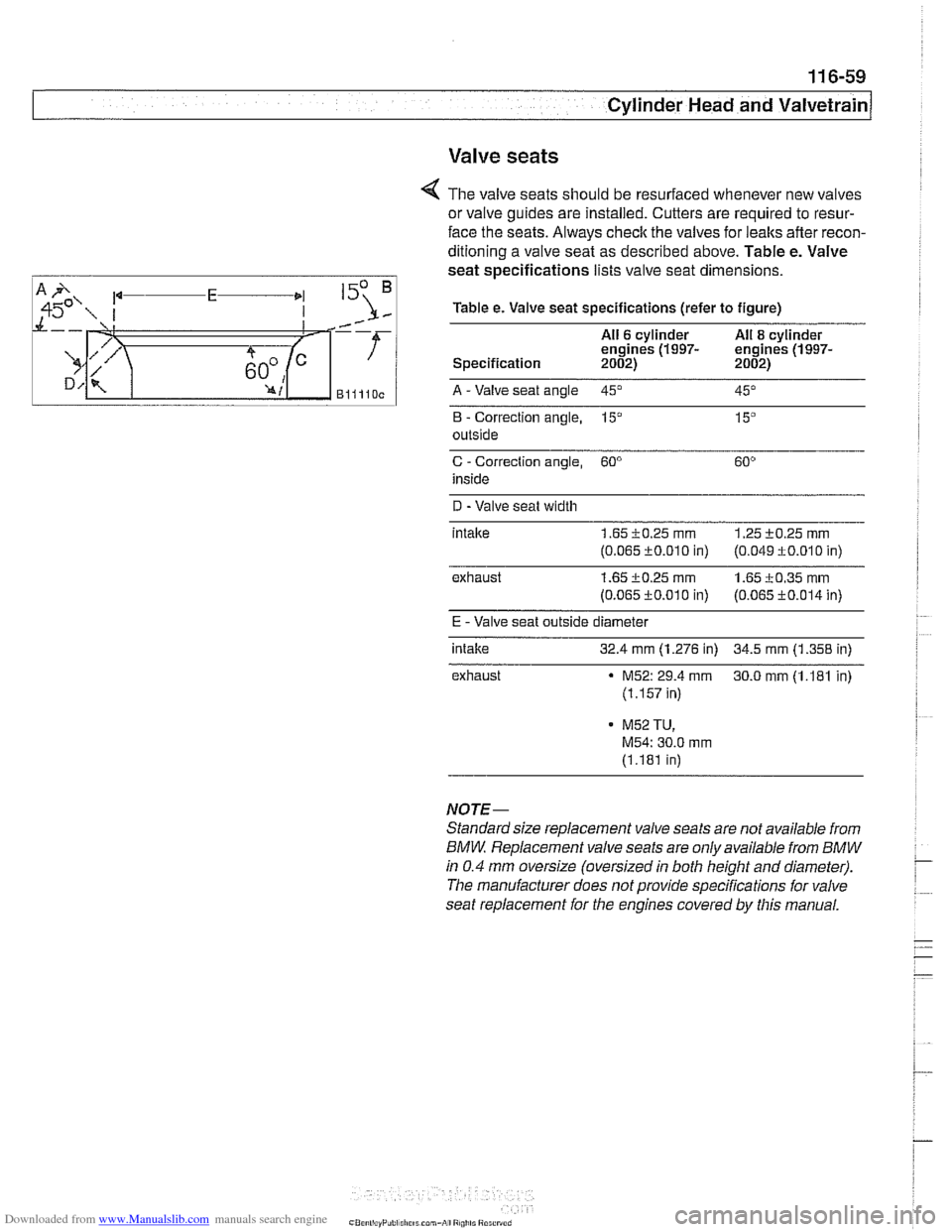
ditioning a valve seat as described above. Table e. Valve
seat specifications lists valve seat dimensions.
Table e. Valve seat specifications (refer to figure)
All
6 cylinder All 8 cylinder
engines (1997- engines (1997- Specification 2002) 2002)
Blllloc A -Valve seat angle 45" --. -- 45"
B - Correction angle, 15" 15"
outside
C - Correction angle, 60"
inside
D -Valve seat width
intalte
1.65 i0.25 rnrn 1.25 +0.25 rnm
(0.065 c0.010 in) (0.049 f 0.010 in)
exhaust
1.65 c0.25 rnm 1.65 i0.35 rnm
(0.065 fO.O1O in) (0.065 c0.014 in)
E - Valve seat outside diameter
intake
32.4 mm (1.276 in) 34.5 mm (1.358 in)
exhaust
M52: 29.4 rnm 30.0 rnm (1.181 in)
(1.157 in)
- M52 TU,
M54: 30.0 mrn
(1.181 in)
NOTE-
Standard size replacement valve seats are not available from
BMW Replacement valve seats are only available from BMW
in 0.4 mm oversize (oversized in both height and diameter).
The manufacturer does not provide specifications for valve
seat replacement for the engines covered by this manual.
Page 647 of 1002
Downloaded from www.Manualslib.com manuals search engine
Front Suspension
/ Front strut top mount assembly
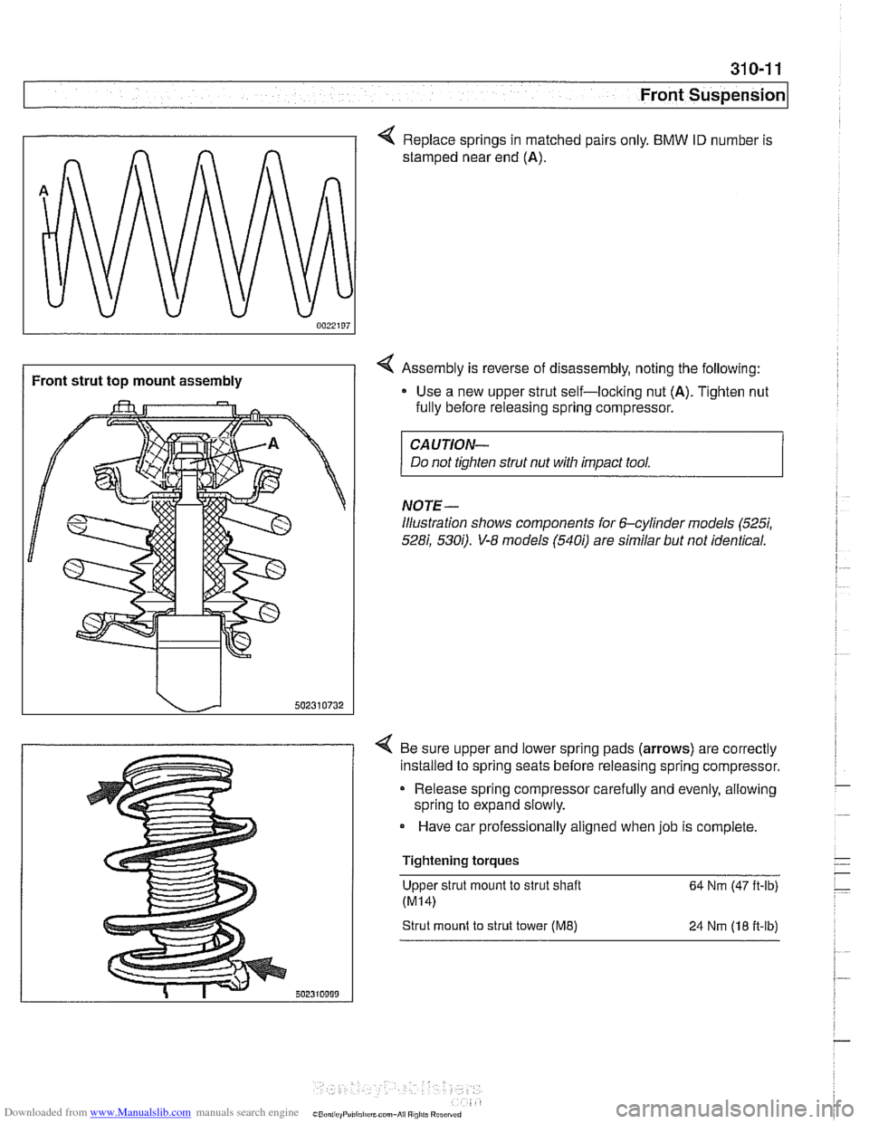
< Replace springs in matched pairs only. BMW ID number is
stamped near end
(A).
4 Assembly is reverse of disassembly, noting the following:
Use a new upper strut self-loclting nut
(A). Tighten nut
fully before releasing spring compressor.
CAUTION-
Do not tighten strut nut with impact tool.
NOTE-
illustration shows components for 6-cylinder models (5257,
528i, 5300. V-8 models (5400 are similar but not identical.
4 Be sure upper and lower spring pads (arrows) are correctly
installed to spring seats before releasing spring compressor.
Release spring compressor carefully and evenly, allowing
spring to expand slowly.
Have car professionally aligned when job is complete.
Tightening torques Upper strut mount to strut shaft
64 Nm (47 ft-lb)
Strut mount to strut tower (ME) 24 Nrn (18 fi-lb)
Page 701 of 1002
Downloaded from www.Manualslib.com manuals search engine
330-5
Rear Suspension
REAR STRUTS AND SPRINGS
(SEDAN MODELS)
Rear strut assembly, removing and
installing
Replace struts and coil springs in pairs only.
- Raise car and remove rear wheels.
WARNING -
Male sure the car is firmly supported on jack stands de-
signed for the purpose. Place jack stands underneath struc-
tural chassis points. Do not place jack stands under
suspension parts.
- Remove rear parcel shelf:
Remove rear seat headrests by pulling straight up.
Remove both rear roof pillar (C-pillar) trim panels.
Unbolt rear seat
belt anchors. See 720 Seat Belts.
Models with fixed rear seat: Remove rear seat backrest.
See 520 Seats.
* Models with fold-down rear seat: Remove rear seat back-
rest side sections. See 520 Seats. Fold down backrest.
* Working inside trunk, remove roller blind mounting nuts
and bolts, if applicable. Also disconnect roller blind har-
ness connector at right edge of rear seat backrest.
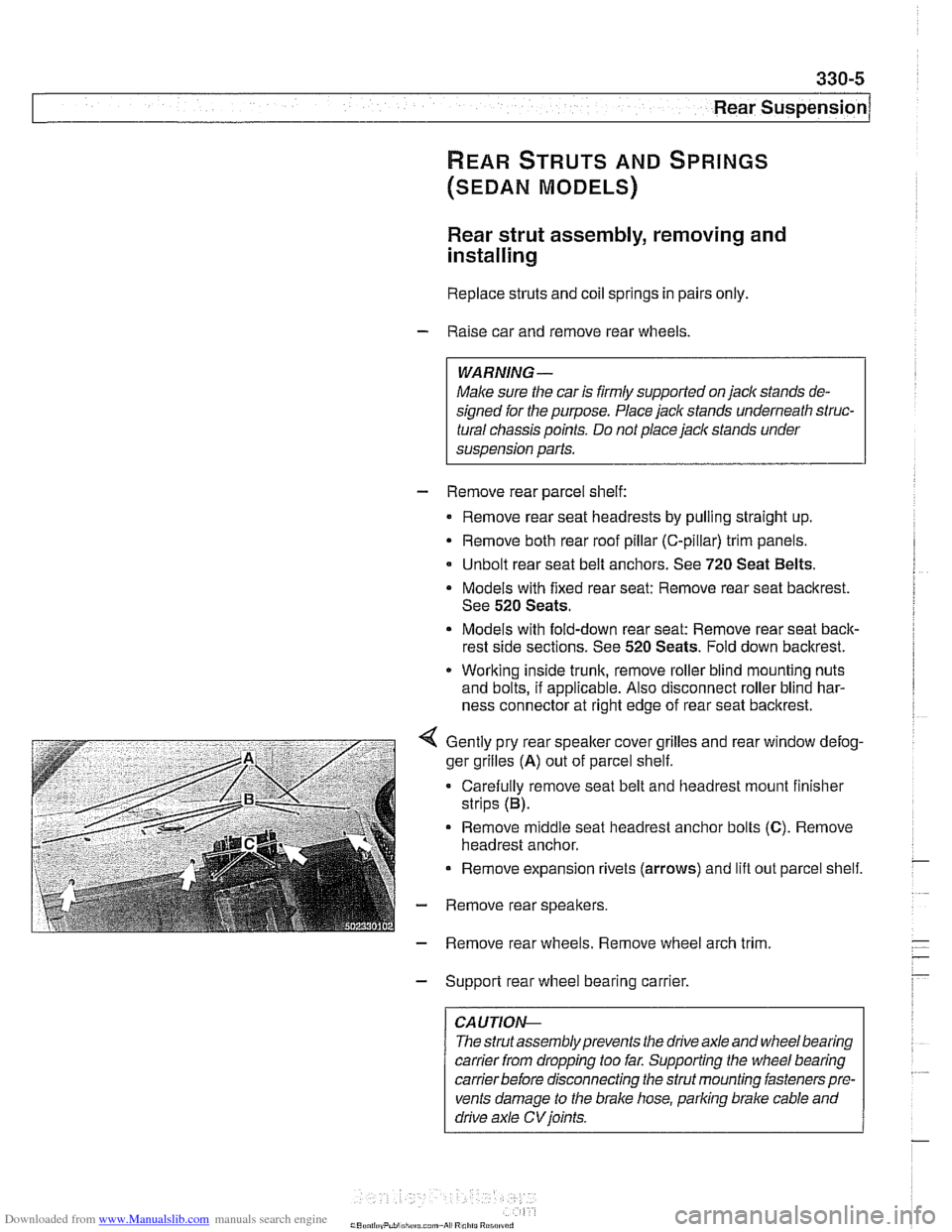
Gently pry rear speaker cover grilles and rear window defog-
ger grilles
(A) out of parcel shelf.
Carefully remove seat belt and headrest mount finisher
strips (B).
Remove
middle seat headrest anchor bolts (C). Remove
headrest anchor.
Remove expansion rivets (arrows) and lift out parcel shelf.
- Remove rear speakers.
- Remove rear wheels. Remove wheel arch trim
- Support rear wheel bearing carrier.
CAUTION-
The strutassembly prevents the drive axle and wheel bearing
carrier
from dropping too far. Supporting the wheel bearing
carrierbefore disconnecting the strut mounting fasteners pre-
vents damage to the brake hose, parking brake cable and
drive axle
CV joints.
Page 704 of 1002
Downloaded from www.Manualslib.com manuals search engine
330-8
Rear Suspension
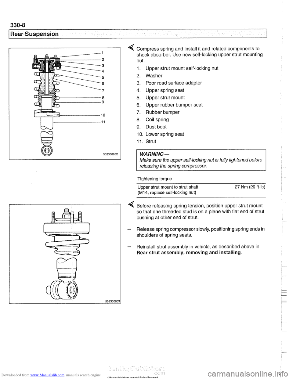
4 Compress spring and install it and related components to
shock absorber. Use new self-locking upper strut mounting
nut.
1. Upper strut mount self-locking nut
2. Washer
3. Poor road surface adapter
4. Upper spring seat
5. Upper strut mount
6. Upper rubber bumper seat
7. Rubber bumper
8. Coil spring
9. Dust boot
10. Lower spring seat
I I. Strut
WARNING-
Male sure the upperself-locking nut is fully tightened before
releasing the spring compressor.
Tightening torque
Upper strut mount to strut shaft
27 Nm (20 ft-lb)
(M14, replace self-locking nut)
4 Before releasing spring tension, position upper strut mount
so that one threaded stud is on a plane with flat end of strut
bushing at other end of strut.
- Release spring compressorslowly, positioning spring ends in
shoulders of spring seats.
- Reinstall strut assembly in vehicle, as described above in
Rear strut assembly, removing and installing.
Page 707 of 1002
Downloaded from www.Manualslib.com manuals search engine
330-1 1
Rear Suspension
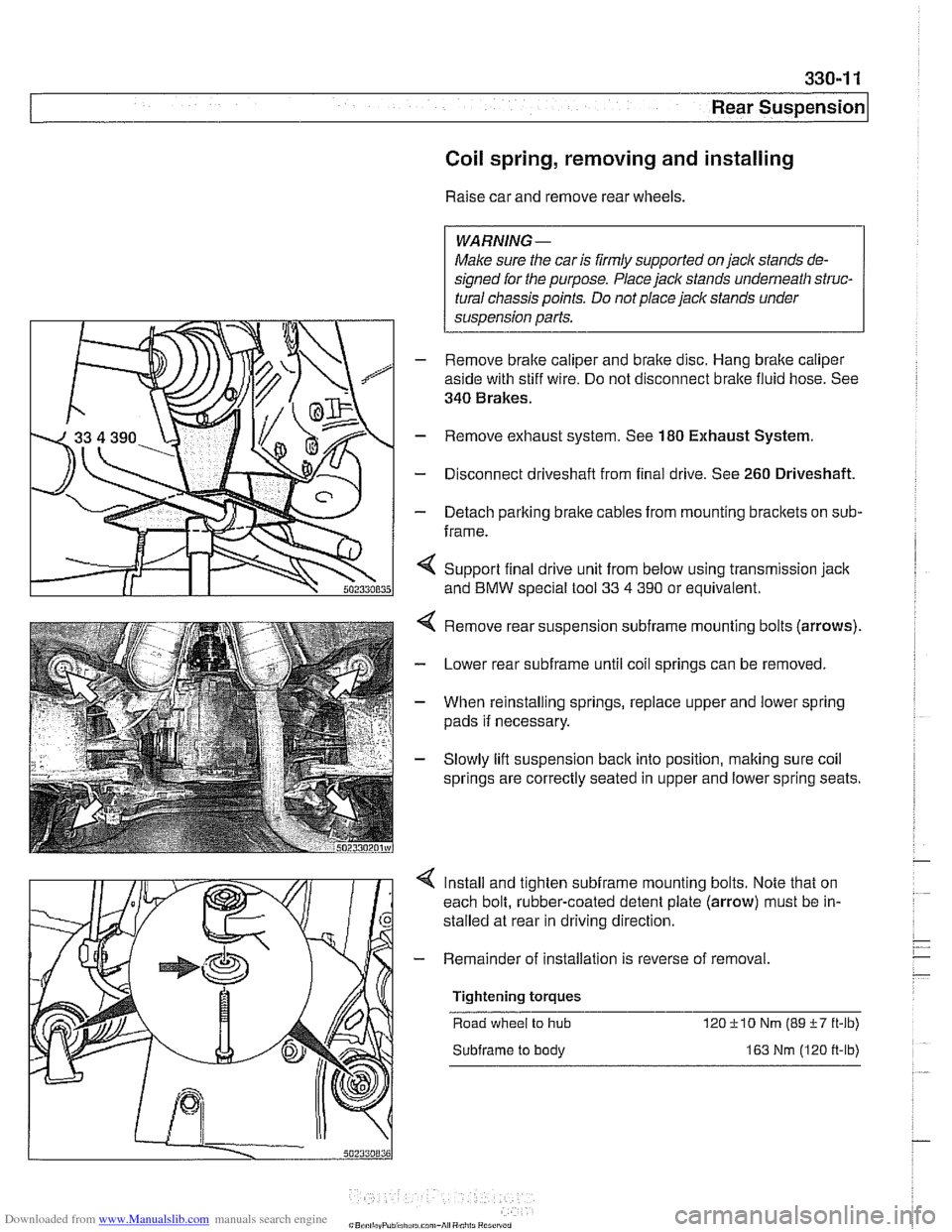
Coil spring, removing and installing
Raise car and remove rear wheels.
WARNING-
Make sure the car is firmly supported on jack stands de-
signed for the purpose. Place jack stands underneath struc-
tural chassis points. Do not place jack stands under
suspension parts.
- Remove brake caliper and brake disc. Hang brake caliper
aside with stiff wire. Do not disconnect
bralte fluid hose. See
340 Brakes.
- Remove exhaust system. See 180 Exhaust System.
- Disconnect driveshafl from final drive. See 260 Driveshaft.
- Detach parking bralte cables from mounting bracltets on sub-
frame.
< Support final drive unit from below using transmission jack
and
BMW special tool 33 4 390 or equivalent.
Remove rear suspension
subframe mounting bolts (arrows).
Lower rear
subframe until coil springs can be removed.
When reinstalling springs, replace upper and lower spring
pads if necessary.
Slowly lift suspension
back into position, making sure coil
springs are correctly seated in upper and lower spring seats.
Install and tighten
subframe mounting bolts. Note that on
each bolt, rubber-coated detent plate (arrow) must be in-
stalled at rear in driving direction
- Remainder of installation is reverse of removal
Tightening torques Road wheel
to hub 12OilO Nm (89i-7 ft-lb)
Subframe to body 163 Nm (120 ft-lb)
Page 724 of 1002
Downloaded from www.Manualslib.com manuals search engine
330-28
Rear Suspension
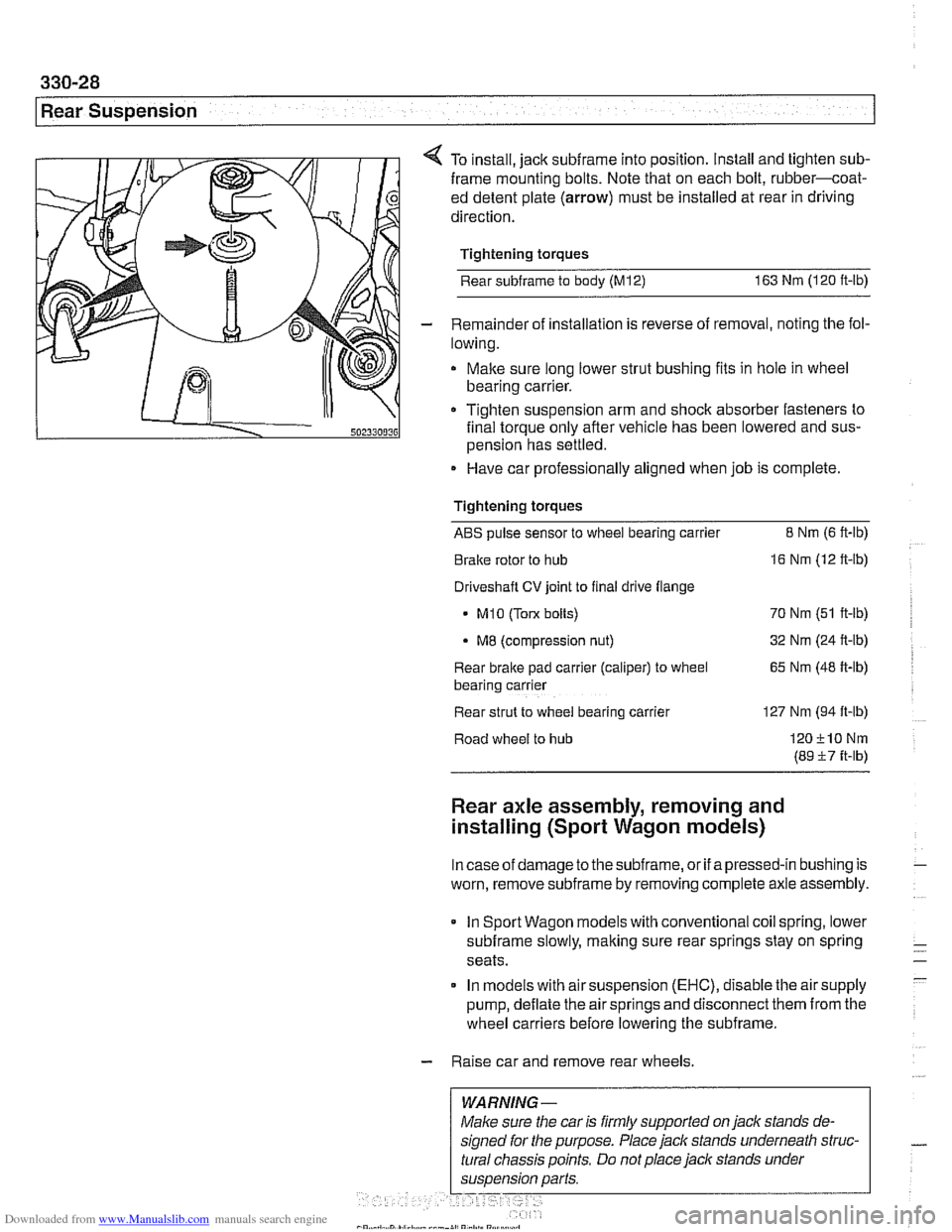
4 To install, jack subframe into position. Install and tighten sub-
frame mounting bolts. Note that on each bolt, rubber-coat-
ed detent plate
(arrow) must be installed at rear in driving
direction.
Tightening torques
Rear
subframe to body (M12) 163 Nm (120 ft-lb)
- Remainder of installation is reverse of removal, noting the fol-
lowing.
Make sure long lower strut bushing fits in hole in wheel
bearing carrier.
111 0 Tighten suspension arm and shoclc absorber fasteners to
502330036 final torque only afler vehicle has been lowered and sus-
pension has settled.
Have car professionally aligned when job is complete
Tightening torques
ABS pulse sensor to wheel bearing carrier 8 Nrn (6 ft-lb)
Brake rotor to hub
16 Nm (12 ft-lb)
Driveshaft
CV joint to final drive flange
- MI0 (Tow bolts) 70 Nm (51 ft-lb)
MB (compression nut) 32
Nm (24 ft-lb)
Rear brake pad
carrler (caliper) to wheel 65 Nm (48 ft-lb)
bear~ng carrler
Rear strut to
wheel bearlng carrler 127 Nm (94 ft-lb)
Road wheel to hub
120210Nrn
(89 57 ft-lb)
Rear axle assembly, removing and
installing (Sport Wagon models)
Incaseof damage to thesubframe, or if apressed-in bushing is
worn, remove
subframe by removing complete axle assembly.
In Sport Wagon models with conventional coil spring, lower
subframe slowly, making sure rear springs stay on spring
seats.
In models with air suspension
(EHC), disable the air supply
pump, deflate the air springs and disconnect them from the
wheel carriers before lowering the subframe.
- Raise car and remove rear wheels.
WARNING-