front alignment BMW 540i 2001 E39 User Guide
[x] Cancel search | Manufacturer: BMW, Model Year: 2001, Model line: 540i, Model: BMW 540i 2001 E39Pages: 1002
Page 613 of 1002
Downloaded from www.Manualslib.com manuals search engine
Driveshaft, aligning
The alignment of the driveshaft does not normally need to be
checked unless the engineltransmission or the final drive
have been removed and installed. if ail other parts of the
driveshaft have been inspected and found to be okay, but
there is still noise or vibration, driveshaft alignment should be
checked.
There are two important driveshaft alignment checks. The
first is to make sure that the driveshaft runs straight from the
transmission to the final drive, without any variation from
side-
to-side caused by misalignment of the engineltransmission in
its mounts. Make a basic check by sighting along the
drive-
shaft from back to front. Any misalignment should be appar-
ent from the center bearing forward.
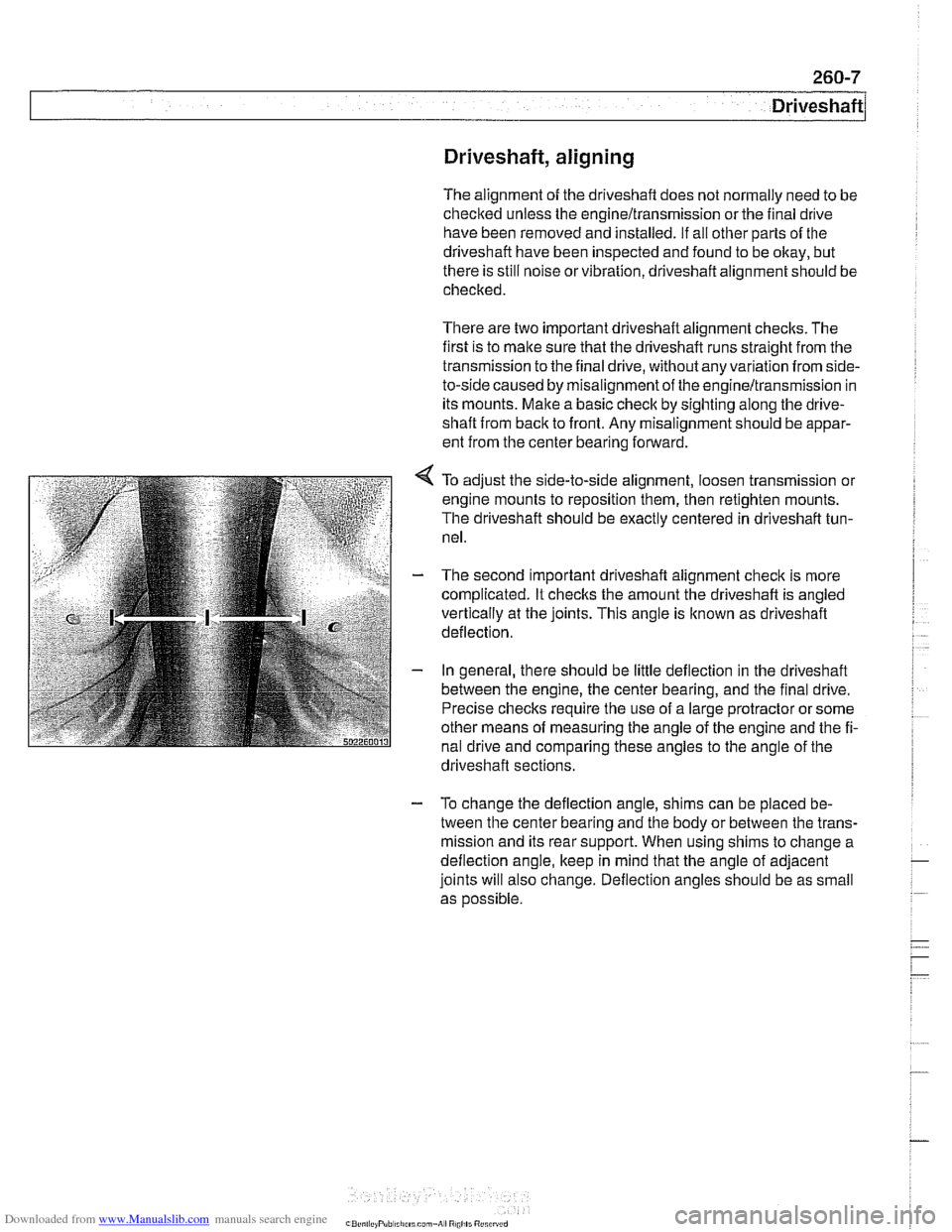
To adjust the side-to-side alignment, loosen transmission or
engine mounts to reposition them, then retighten mounts.
The driveshaft should be exactly centered in driveshaft tun-
nel.
The second important driveshaft alignment check is more
complicated. It checlts the amount the driveshaft is angled
vertically at the joints. This angle is
lknown as driveshaft
deflection.
In general, there should be little deflection in the driveshaft
between the engine, the center bearing, and the final drive.
Precise checks require the use of a large protractor or some
other means of measuring the angle of the engine and the fi-
nal drive and comparing these angles to the angle of the
. . driveshaft sections.
- To change the deflection angle, shims can be placed be-
tween the center bearing and the body or between the trans-
mission and its rear support. When using shims to change a
deflection angle, keep in mind that the angle of adjacent
joints will also change. Deflection angles should be as small
as
oossible.
Page 622 of 1002
Downloaded from www.Manualslib.com manuals search engine
[~us~ension, Steering and Brakes - General
This section of the manual covers front and rear suspension,
braking and steering systems, and contains wheel, tire and
wheel alignment information and specifications. Also covered
here are the integrated braking and suspension systems in-
cluding
antilock braking (ABS), traction control (ASCIDSC),
and electronic height control (EHC).
Vehicle ride height information is at the end of this repair
group. Alignment information is in
320 Steering and Wheel
Alignment.
Aluminum suspension components
In order to reduce vehicle weight, aluminum suspension com-
ponents are used in some models. A test with a magnet will
easily reveal the metal used. If working with aluminum com-
ponents, be sure to read and follow the cautions below.
CAUTION-
* Due to the chemical and corrosion characteristics of alumi-
num, do not bring into contact with battery acid.
Do not use wire brushes with brass or iron bristles.
Only use brushes with stainless steel bristles.
Do not expose to flying sparks from
grinding/cutting op-
erations.
Do not subject to steel welding splashes.
Do not expose to temperatures over
80°C (176"F),
even for short periods. Temperatures in painting facili-
ties are not a problem.
The E39 front suspension subframe is used as a rigid mount-
ing platform for the front suspension arms, stabilizer bar and
steering gear.
The suspension arms, known as the lower control arms and
the tension struts (thrust arms), are connected to the
sub-
frame through rubber bushings. The arms are connected to
the steering
knucltles in a double pivot configuration.
Each front strut assembly includes a tubular strut and a coil
spring. The upper strut mount includes a bearing. The lower
end of each strut housing is fitted to the steering knuckle. The
integral wheel bearing and hub are bolted to the steering
Iknucltle.
6-cylinder and V-8 models use different steering systems and
other front suspension components.
Page 659 of 1002
Downloaded from www.Manualslib.com manuals search engine
1 320 Steering and Wheel Alignment
General ........................... .32 0.2
Special tools
........................ .32 0.2
Steering system
..................... .32 0.4
Steering system variations
............. .32 0.5
Steering system warnings and cautions
... .32 0.6
Steering Wheel .................... .32 0.7
Steering wheel. removal and installation
.. .32 0.7
Steering Column ................. .32 0.1 0
Steering column components .......... .32 0.10
Steering column trim, removing
and replacing
...................... .32 0.10
lgnition switch ring antenna (EWS).
removing and installing
............... .32 0.1 1
lgnition lock cylinder.
removing and installing
............... .32 0-1 1
Steering column lock. removing
and installing
....................... .32 0.12
lgnition
interloclc cable. removing and installing
(models with automatic transmission)
... .32 0.13
Interlock cable. adjusting
(models with automatic transmission)
... .32 0.14
Steering column. removing and installing
. .32 0.14
Steering column adjustment motors.
removing and installing
............... .32 0.16
Power Steering Pump ............. .32 0.17
Power steering pump. removing
and installing
....................... .32 0.1 7
Power steering system.
bleeding and filling
.................. .32 0.18
Rack and Pinion Steering
(6-cylinder models)
............... 320-19
Rack and pinion steering components
(6-cylinder models)
.................. 320-1 9
Steering rack. removing and installing
.... 320-19
Steering
rack boot. replacing ........... 320-22
Tie rod (outer). replacing
.............. 320-22
Tie rod (inner). replacing
.............. 320-23
Steering Gearbox (V-8 models) .... 320-24
Steering gearbox system components
. .
(V-8 models) ....................... 320-24
Steering gearbox, removing and installing 320-25
Pitman arm. removing and installing ..... 320-28
Pitman arm. adjusting ................ 320-29
Steering idler arm. removing
and installing
....................... 320-30
Idler arm bushing. replacing ........... 320-31
Center tie rod. replacing
.............. 320-32
Wheel Alignment .................. 320-33
Camber
........................... 320-33
Caster
............................ 320-33
Front toe and toe difference angle
....... 320-34
Reartoe ........................... 320-34
Preparing for alignment
............... 320-35
Alignment specifications tables
......... 320-35
Page 675 of 1002
Downloaded from www.Manualslib.com manuals search engine
Steering and Wheel Alignment
Power assist is provided by a belt-driven pump at the lower
left front of the engine. The power steering fluid reservoir is lo-
cated at the left side of the engine compartment.
Power steering pump, removing and
installing
When working with power steering components, absolute
cleanliness is needed to ensure proper operation of the hy-
- Empty power steering fluid reservoir using clean syringe. Do
not reuse fluid.
- Raise front of car. Remove splash shield from under engine.
WARNING-
Make sure the car is firmly supported on jack stands de-
signed for the purpose. Place jack stands beneath structural
chassis points. Do not place jack stands under suspension
Darts.
Remove drive belt from power steering pump. See
020 Main-
tenance.
Remove alternator cooling duct
Remove fluid hoses from pump. Plug openings in pump and
hose ends.
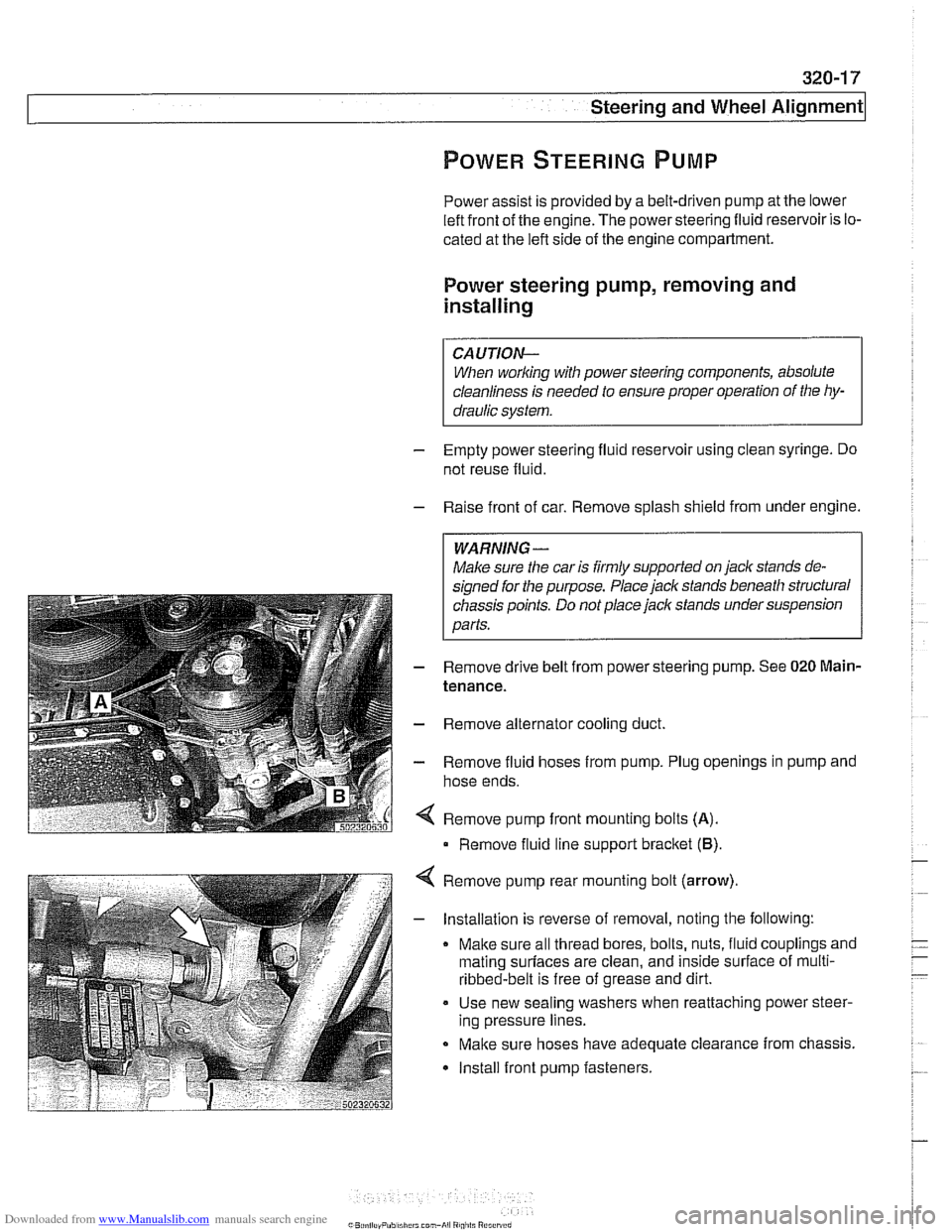
Remove pump front mounting bolts
(A).
Remove fluid line support bracket (B)
Remove pump rear mounting bolt (arrow)
- Installation is reverse of removal, noting the following:
Make sure all thread bores, bolts, nuts, fluid couplings and
mating
surfaces are clean, and inside surface of multi-
ribbed-belt is free of grease and dirt.
Use new sealing washers when reattaching power steer-
ing pressure lines.
Make sure hoses have adequate clearance from chassis.
Install front pump fasteners.
Page 677 of 1002
Downloaded from www.Manualslib.com manuals search engine
i Steering and Wheel Alignment
RACK AND PINION STEERING
(6-CYLINDER MODELS)
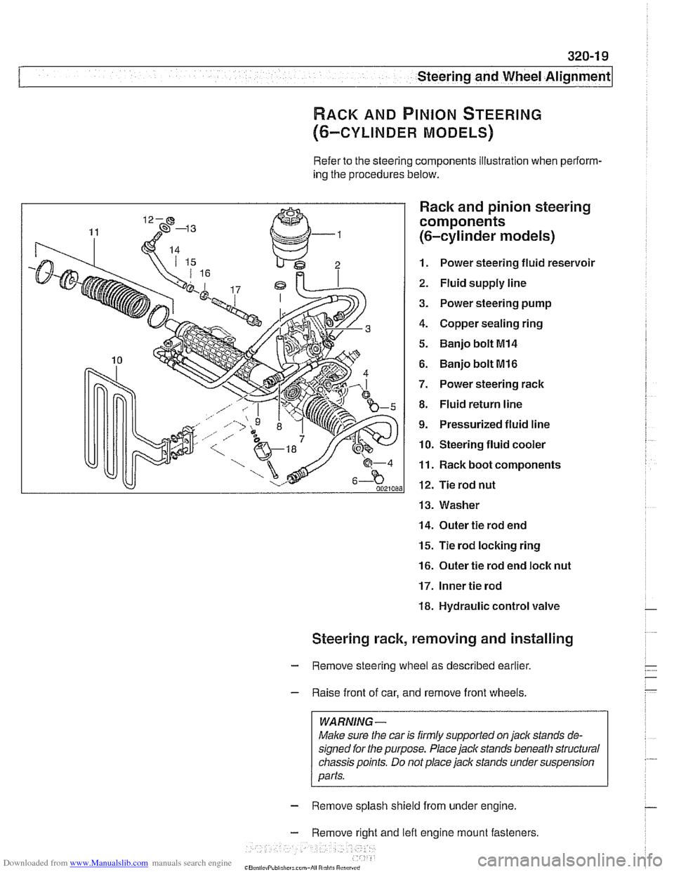
Refer to the steering components illustration when perform-
ing the procedures below.
Rack and pinion steering
components
(6-cylinder models)
1. Power steering fluid reservoir
2. Fluid supply line
3. Power steering pump
4. Copper sealing ring
5. Banjo bolt MI4
6. Banjo bolt MI6
7. Power steering rack
8. Fluid return line
9. Pressurized fluid line
10. Steering fluid cooler
11. Rack boot components
12. Tie rod nut
13. Washer
14. Outer tie rod end
15. Tie rod locking ring
16. Outer tie rod end loclc nut
17. Inner tie rod
18. Hydraulic control valve
Steering rack, removing and installing
- Remove steering wheel as described earlier.
- Raise front of car, and remove front wheels.
WARNING -
Male sure the car is firmly supported on jack stands de-
signed for the purpose. Place jack stands beneath structural
chassis points. Do
not place jack stands under suspension
parts.
- Remove splash shield from under engine.
- Remove right and lefl engine mount fasteners
-" ., - , . ,
Page 680 of 1002
Downloaded from www.Manualslib.com manuals search engine
--. --
Steering and Wheel Alignment
Steering rack boot, replacing
- Remove outer tie rod end. See Tie rod (outer), replacing
- Cut rack boot band clamps and remove boot.
- Cut rack boot band clamp and slide bellows back. Inspect
boot for any sign of damage. Replace
if necessary.
NOTE-
New rack boot lit comes with new band clamp.
- Grease tie rod taper so that small end of rack boot slides on
tie rod when tie rod is tightened, preventing raclc boot from
twisting.
- Slide new boot into position and replace band clamps
Tie rod (outer), replacing
LOCI( nut Locking ring
- Raise front of car. Remove road wheel
WARNING-
Male sure caris firmly suppoiiedon jackstands designed for
the purpose. Place jack stands beneath structural chassis
ooints. Do not olace iack stands under
susoension oaiis.
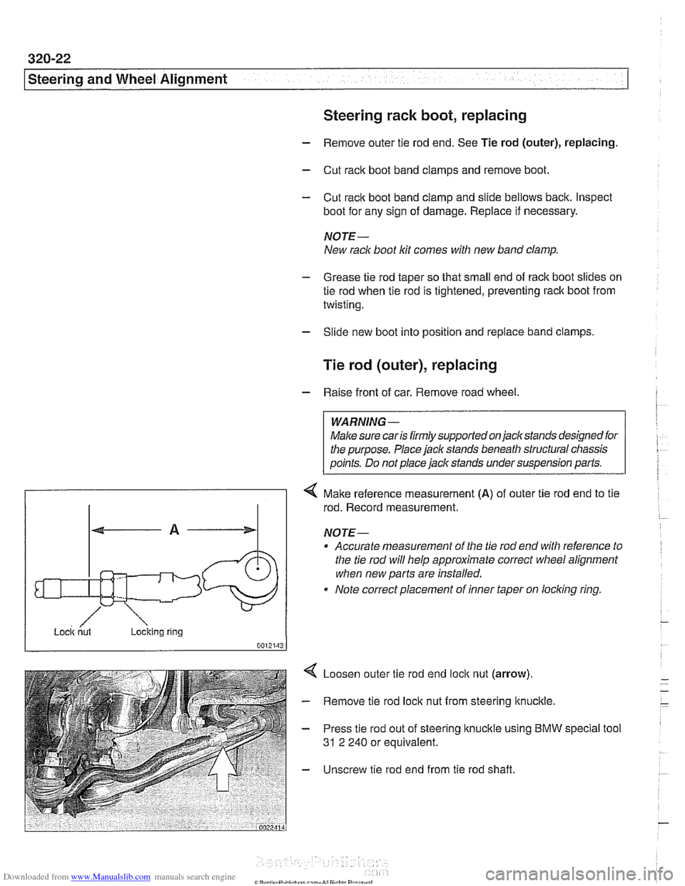
4 Make reference measurement (A) of outer tie rod end to tie
rod. Record measurement.
NOTE-
Accurate measurement of the tie rod end with reference to
the tie rod will help approximate correct
wheel alignment
when new parts are installed.
Note correct placement of inner taper on
loclcing ring.
Loosen outer tie rod end
loclc nut (arrow).
Remove tie rod lock nut from steering
ltnuclcle.
Press tie rod out of steering knuckle using BMW
31 2 240 or equivalent. special tool
Unscrew tie rod end from tie rod shaft.
Page 686 of 1002
Downloaded from www.Manualslib.com manuals search engine
320-28
[steering and Wheel Alignment
Pitman arm, removing and installing
- Raise front of car. Remove splash shield from under engine.
Male sure the car is
firmly supported on jack stands de-
signed for the purpose. Place jack stands beneath structural
chassis points. Do not place
jaclc stands under suspension
parts.
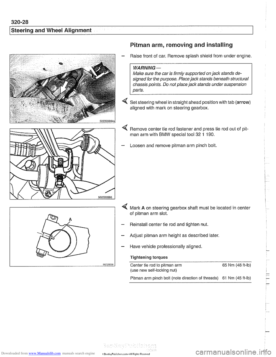
4 Set steering wheel in straight ahead position with tab (arrow)
aligned with mark on steering gearbox.
Remove center tie rod fastener and press tie rod out of pit.
man arm with BMW special
too1 32 1 190.
- Loosen and remove pitman arm pinch bolt
4 Mark A on steering gearbox shalt must be located in center
of
pitman arm slot.
- Reinstall center tie rod and tighten nut.
- Adjust pitman arm height as described later.
- Have vehicle professionally aligned.
Tightening torques
50:s,n5m Center tie rod to pitman arm 65
Nm (48 ft-lb)
(use new self-locking nut)
Pitman arm pinch bolt (note direction of threads) 61 Nrn (45 ft-lb)
Page 687 of 1002
Downloaded from www.Manualslib.com manuals search engine
Steering and Wheel Alignment
Pitman arm, adjusting
As the vehicle suspension settles down, the toe on the left
and right wheels must remain identical for proper handling.
By adjusting the height of the
pitman arm, the left and right tie
rods are moved to the same ride level setting. This will opti-
mize straight-ahead travel on uneven road surfaces.
- Raise front of car. Remove splash shield from under engine.
WARNING-
Male sure the car is iirmly supported on jack stands de-
signed ior the purpose. Place jack stands beneath structural
chassis points. Do not place
jaclc stands under suspension
parts.
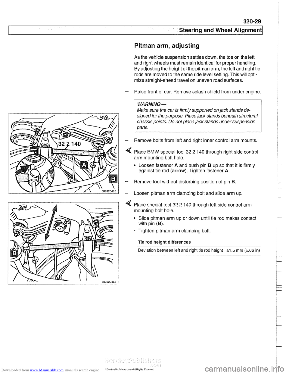
- Remove bolts from left and right inner control arm mounts.
Place
BMW special tool 32 2 140 through right side control
arm mounting bolt hole.
Loosen fastener
A and push pin El up so that it is firmly
against tie rod
(arrow). Tighten fastener A.
- Remove tool without disturbing position of pin El.
- Loosen pitman arm clamping bolt and slide arm up.
4 Place special tool 32 2 140 through left side control arm
mounting bolt hole.
Slide
pitman arm up or down until tie rod makes contact
with pin
(El).
Tighten pitman arm clamping bolt.
Tie rod height differences
Deviation between
left and right tie rod height -?-I .5 rnrn (LO6 in)
Page 688 of 1002
Downloaded from www.Manualslib.com manuals search engine
I Steering and Wheel Alignment
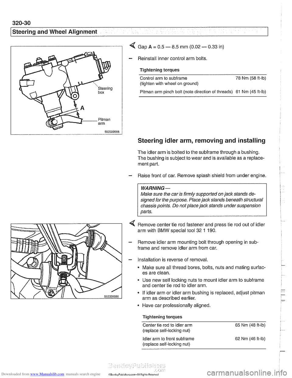
I I 4 Gap A = 0.5 - 8.5 mm (0.02 - 0.33 in)
- Reinstall inner control arm bolts
Tightening torques
Control arm to
subframe 78 Nm (58 it-lb)
(tighten with wheel on ground)
Pitman arm pinch bolt (note direction of threads) 61 Nm (45 ft-lb)
Steering idler arm, removing and installing
The idler arm is bolted to the subframe through a bushing.
The bushing is subject to wear and is available as a replace-
ment part.
- Raise front of car. Remove splash shield from under engine.
WARNING -
Male sure the car is firmly supported on jaclc stands de-
signed for the purpose. Place jack stands beneath structural
chassis points. Do not place jack stands under suspension
parts.
4 Remove center tie rod fastener and press tie rod out of idler
arm with
BMW special tool 32 1 190.
- Remove idler arm mounting bolt through opening in sub-
frame and remove idler arm from car.
- Installation is reverse of removal.
Make sure all thread bores, bolts, nuts and mating surfac-
es are clean.
Use new self
loclting nuts to mount idler arm to subframe
and center tie rod to idler arm.
If idler arm or idler arm bushing is replaced, adjust
pitman
arm as described earlier.
Have car professionally aligned.
Tightening torques
Center tie rod to idler arm 65 Nm (48 ft-ib)
(replace self-locking nut)
Idler arm to front subirame
(replace self-locking nut) 62
Nm (46 it-lb)
Page 690 of 1002
Downloaded from www.Manualslib.com manuals search engine
320-32
Steering and Wheel Alignment
Center tie
rod, replacing
- Raise front of car. Remove splash shield from under engine.
WARNING-
Make sure tlie car is firmly supported on jack stands de-
signed for the purpose. Place jack stands beneath structural
cliassis points. Do not place jack stands under suspension
parts.
- Measure length of left and right (outer) tie rods. Write down
measurements.
NOTE-
Accurate measurement of the tie rod end with reference to
the center tie rod will help approximate correct wheel align-
ment when new parts are installed.
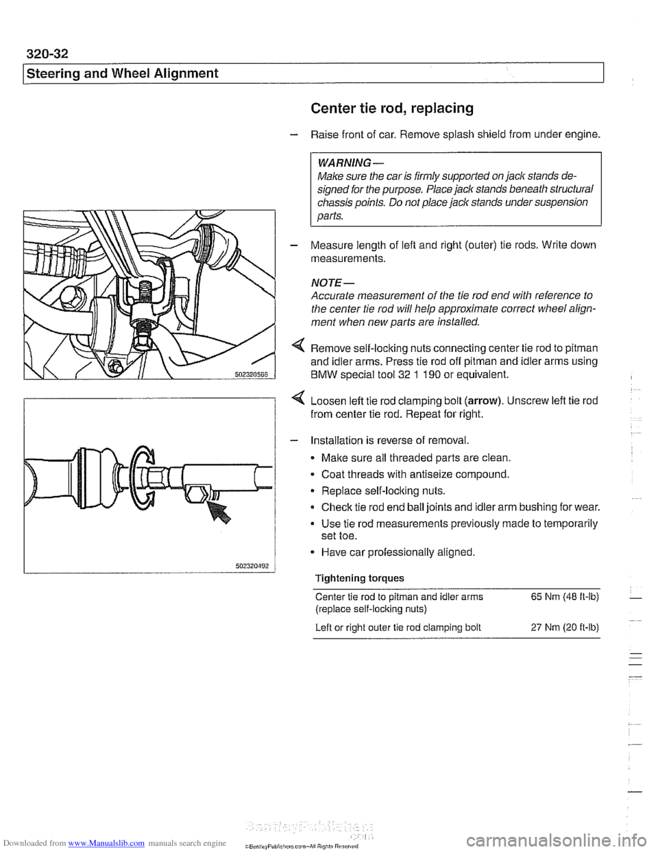
4 Remove self-loclting nuts connecting center tie rod to pitman
and idler arms. Press tie rod off pitman and idler arms using
BMW special tool
32 1 190 or equivalent.
4 Loosen left tie rod clamping bolt (arrow). Unscrew left tie rod
from center tie rod. Repeat for right.
- Installation is reverse of removal.
Malte sure all threaded parts are clean.
. Coat threads with antiseize compound.
Replace self-loclting nuts.
Check tie rod end ball joints and idler arm bushing for wear.
Use tie rod measurements previously made to temporarily
set toe.
- Have car professionally aligned.
Tightening torques
Center tie rod to
pitman and idler arms 65 Nm (48 ft-lb)
(replace self-locking nuts)
Left or right outer
tie rod clamping bolt 27 Nm (20 it-lb)