sensor BMW 550I GT 2011 F07 Owner's Manual
[x] Cancel search | Manufacturer: BMW, Model Year: 2011, Model line: 550I GT, Model: BMW 550I GT 2011 F07Pages: 297, PDF Size: 8.59 MB
Page 13 of 297
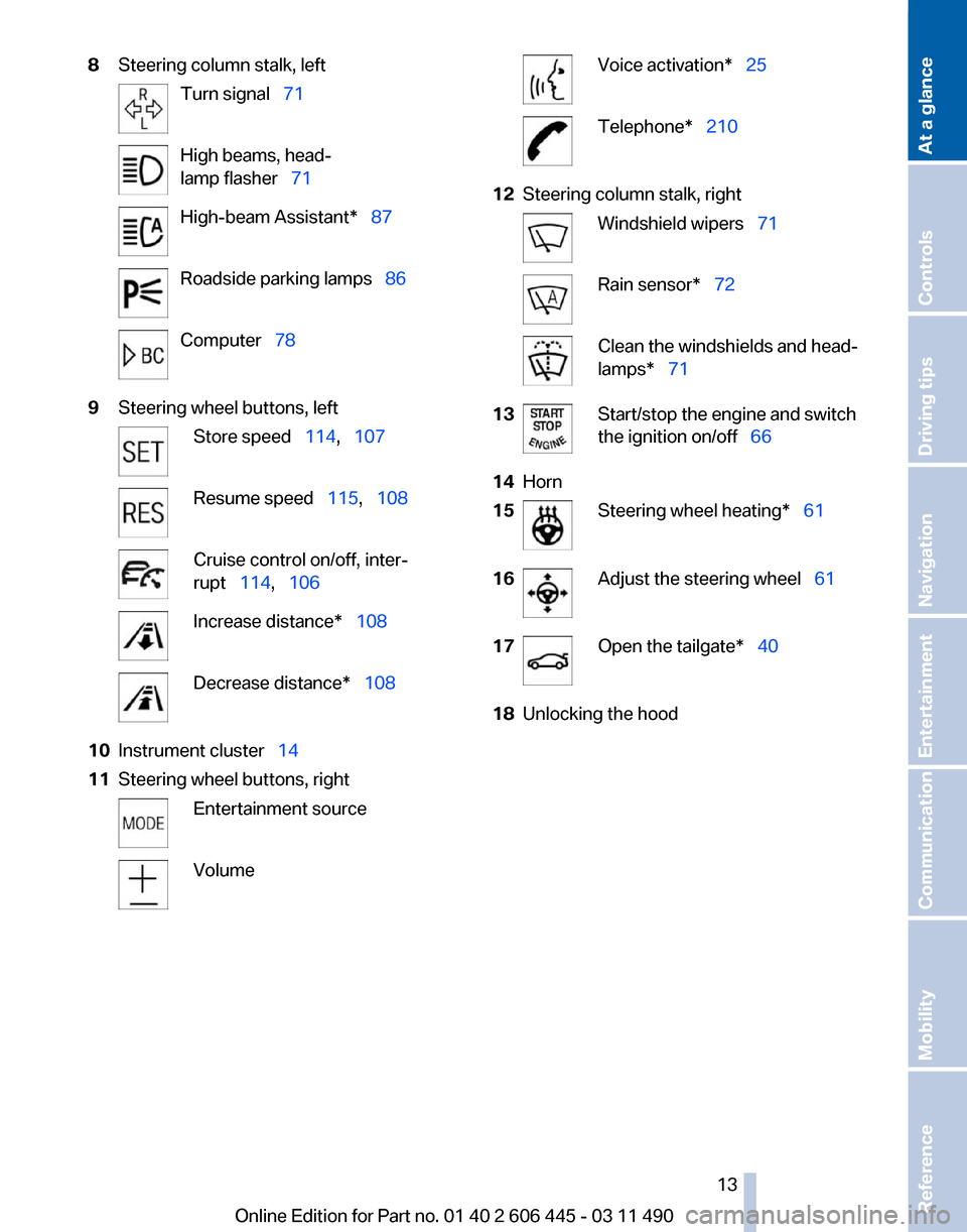
8
Steering column stalk, left Turn signalтАВтАЕ71
High beams, headтАР
lamp flasherтАВтАЕ71
High-beam Assistant*тАВтАЕ87
Roadside parking lampsтАВтАЕ86
ComputerтАВтАЕ78
9 Steering wheel buttons, left Store speedтАВтАЕ114,тАВтАЕ107
Resume speedтАВтАЕ115,тАВтАЕ108
Cruise control on/off, interтАР
ruptтАВтАЕ114,тАВтАЕ106
Increase distance*тАВтАЕ108
Decrease distance*тАВтАЕ108
10 Instrument clusterтАВтАЕ 14
11 Steering wheel buttons, right Entertainment source
Volume Voice activation*тАВтАЕ25
Telephone*тАВтАЕ210
12 Steering column stalk, right Windshield wipersтАВтАЕ71
Rain sensor*тАВтАЕ
72 Clean the windshields and headтАР
lamps*тАВтАЕ71
13 Start/stop the engine and switch
the ignition on/offтАВтАЕ66
14 Horn
15 Steering wheel heating*тАВтАЕ61
16 Adjust the steering wheelтАВтАЕ
61
17 Open the tailgate*тАВтАЕ40
18 Unlocking the hood
Seite 13
13Online Edition for Part no. 01 40 2 606 445 - 03 11 490
Reference Mobility Communication Entertainment Navigation Driving tips Controls
At a glance
Page 44 of 297
Alarm system*
The concept
The vehicle alarm system responds to:
тЦ╖
Opening of a door, the hood or the tailgate.
тЦ╖ Movements in the vehicle: interior motion
sensor, refer to page 45.
тЦ╖ Changes in the vehicle tilt, e.g., during atтАР
tempts to steal a wheel or when towing the
car.
тЦ╖ Interruptions in battery voltage.
The alarm system briefly indicates tampering:
тЦ╖ By sounding an acoustic alarm.
тЦ╖ By switching on the hazard warning system.
тЦ╖ By flashing the high beams.
Arming and disarming the alarm
system
General information
When
you lock or unlock the vehicle, either with
the remote control or at the door lock*, the alarm
system is armed or disarmed at the same time.
Door lock and armed alarm system
Unlocking via the door lock will trigger the alarm
on some country-specific versions.
Tailgate and armed alarm system
The tailgate can be opened using the remote
control, even if the alarm system is armed.
тЦ╖ Press the button on the remote
control
for approx. 1 second and reтАР
lease.
The small tailgate opens slightly. тЦ╖
With automatic trunk lid operation*:
Press the button on the remote
control for approx. 1 second and release.
The large tailgate opens automatically. Note the opening height of the large tailтАР
gate
The tailgate pivots back and up when it opens.
Ensure that there is sufficient clearance when the large tailgate opens; otherwise, damage may
result.тЧА
After
the tailgate is closed, it is locked and moniтАР
tored again by the alarm system. The hazard
warning system flashes once.
In some vehicle equipment variants, the tailgate
can only be opened using the remote control if
the vehicle was unlocked first.
Panic mode*
Press the button on the remote control
for at least 3 seconds.
Switching off the alarm
тЦ╖ Unlock the vehicle using the remote control.
тЦ╖ With Comfort Access: If you are carrying the
remote control with you, pull on the door
handle.
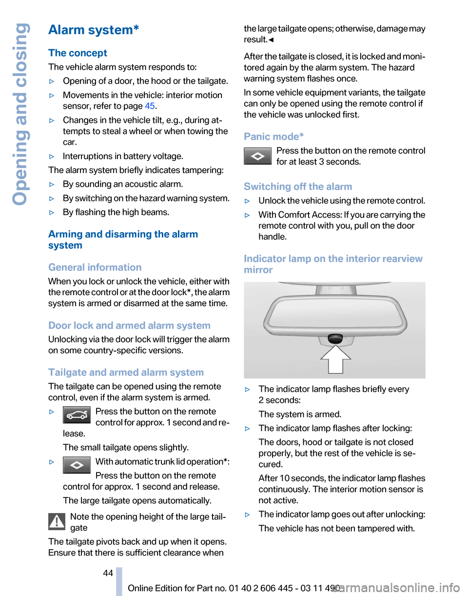
Indicator lamp on the interior rearview
mirror тЦ╖
The indicator lamp flashes briefly every
2 seconds:
The system is armed.
тЦ╖ The indicator lamp flashes after locking:
The doors, hood or tailgate is not closed
properly, but the rest of the vehicle is seтАР
cured.
After
10 seconds, the indicator lamp flashes
continuously. The interior motion sensor is
not active.
тЦ╖ The indicator lamp goes out after unlocking:
The vehicle has not been tampered with. Seite 44
44 Online Edition for Part no. 01 40 2 606 445 - 03 11 490
Opening and closing
Page 45 of 297
тЦ╖
The indicator lamp flashes after unlocking
until
the engine is started, but no longer than
approx. 5 minutes:
An alarm has been triggered.
Tilt alarm sensor
The tilt of the vehicle is monitored.
The alarm system responds in situations such
as attempts to steal a wheel or tow the car.
Interior motion sensor
The
windows and glass sunroof* must be closed
for the system to function properly.
Avoiding unintentional alarms
The tilt alarm sensor and interior motion sensor
can be switched off together, such as in the folтАР
lowing situations:
тЦ╖ In automatic car washes
тЦ╖ In duplex garages.
тЦ╖ During transport on car-carrying trains, at
sea or on a trailer.
тЦ╖ When animals are to remain in the vehicle.
Switching off the tilt alarm sensor and
interior motion sensor Press the button on the remote control
twice in succession.
The indicator lamp lights up for approx. 2 secтАР
onds and then flashes continuously.
The
tilt alarm sensor and interior motion sensor
are switched off until the vehicle is locked again.
Power windows
General information
Take the remote control with you
Take the remote control with you when
leaving the vehicle so that children, for example,
cannot operate the power windows and injure
themselves.тЧА Opening
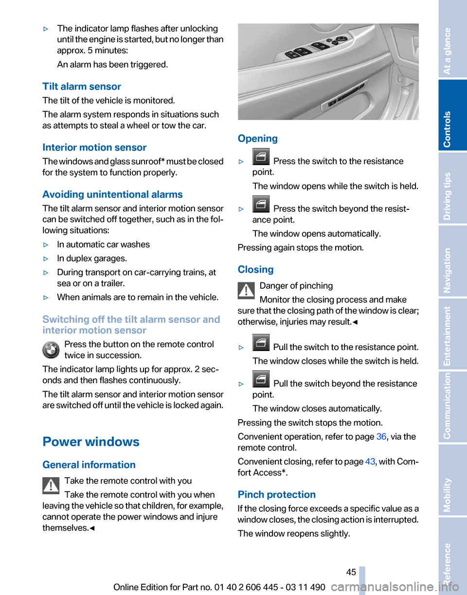
тЦ╖
Press the switch to the resistance
point.
The window opens while the switch is held.
тЦ╖ Press the switch beyond the resistтАР
ance point.
The window opens automatically.
Pressing again stops the motion.
Closing
Danger of pinching
Monitor the closing process and make
sure
that the closing path of the window is clear;
otherwise, injuries may result.тЧА
тЦ╖ Pull
the switch to the resistance point.
The window closes while the switch is held.
тЦ╖ Pull the switch beyond the resistance
point.
The window closes automatically.
Pressing the switch stops the motion.
Convenient operation, refer to page 36, via the
remote control.
Convenient
closing, refer to page 43, with ComтАР
fort Access*.
Pinch protection
If the closing force exceeds a specific value as a
window closes, the closing action is interrupted.
The window reopens slightly. Seite 45
45Online Edition for Part no. 01 40 2 606 445 - 03 11 490
Reference Mobility Communication Entertainment Navigation Driving tips
Controls At a glance
Page 72 of 297
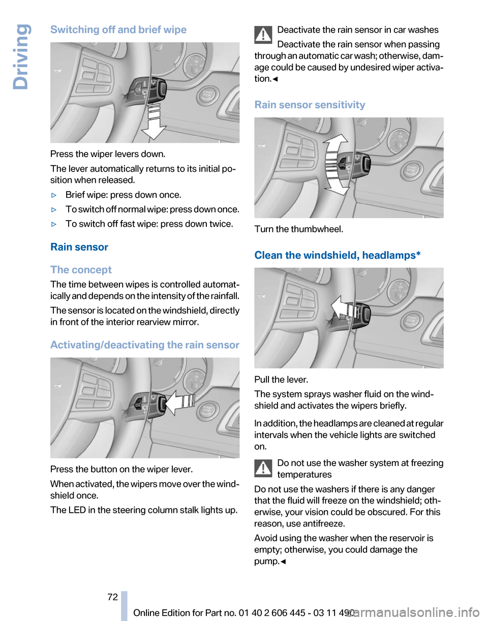
Switching off and brief wipe
Press the wiper levers down.
The lever automatically returns to its initial poтАР
sition when released.
тЦ╖
Brief wipe: press down once.
тЦ╖ To switch off normal wipe: press down once.
тЦ╖ To switch off fast wipe: press down twice.
Rain sensor
The concept
The time between wipes is controlled automatтАР
ically
and depends on the intensity of the rainfall.
The sensor is located on the windshield, directly
in front of the interior rearview mirror.
Activating/deactivating the rain sensor Press the button on the wiper lever.
When
activated, the wipers move over the windтАР
shield once.
The LED in the steering column stalk lights up. Deactivate the rain sensor in car washes
Deactivate the rain sensor when passing
through
an automatic car wash; otherwise, damтАР
age could be caused by undesired wiper activaтАР
tion.тЧА
Rain sensor sensitivity Turn the thumbwheel.
Clean the windshield,
headlamps* Pull the lever.
The system sprays washer fluid on the windтАР
shield and activates the wipers briefly.
In
addition, the headlamps are cleaned at regular
intervals when the vehicle lights are switched
on.
Do not use the washer system at freezing
temperatures
Do not use the washers if there is any danger
that the fluid will freeze on the windshield; othтАР
erwise, your vision could be obscured. For this
reason, use antifreeze.
Avoid using the washer when the reservoir is
empty; otherwise, you could damage the
pump.тЧА Seite 72
72 Online Edition for Part no. 01 40 2 606 445 - 03 11 490
Driving
Page 86 of 297
The setting is stored for the remote control curтАР
rently in use.
Automatic headlamp control
Switch
position : the low beams are switched
on and off automatically, e.g., in tunnels, in twiтАР
light or if there is precipitation. The indicator
lamp in the instrument cluster lights up.
A blue sky with the sun low on the horizon can
cause the lights to be switched on.
The low beams always stay on when the fog
lamps are switched on.
Personal responsibility
The automatic headlamp control cannot
serve
as a substitute for your personal judgment
in determining when the lamps should be
switched on in response to ambient lighting
conditions.
For example, the sensors are unable to detect
fog or hazy weather. To avoid safety risks, you
should always switch on the lamps manually unтАР
der these conditions.тЧА
Daytime running lights*
With the ignition switched on, the daytime runтАР
ning lights light up in position 0, or .
After the ignition is switched off, the parking
lamps light up in position
.
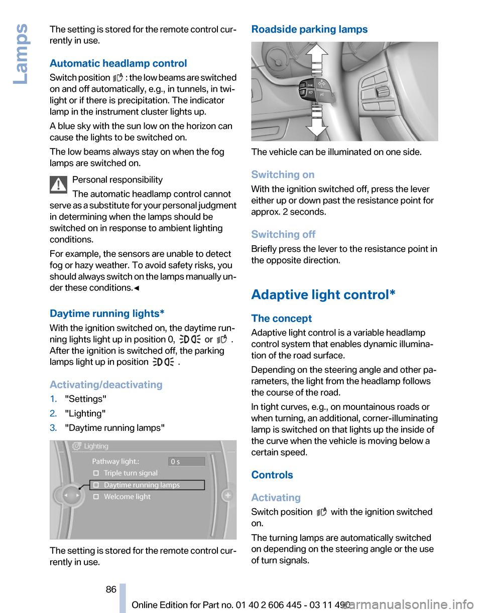
Activating/deactivating
1. "Settings"
2. "Lighting"
3. "Daytime running lamps" The setting is stored for the remote control curтАР
rently in use. Roadside parking lamps
The vehicle can be illuminated on one side.
Switching on
With the ignition switched off, press the lever
either up or down past the resistance point for
approx. 2 seconds.
Switching off
Briefly press the lever to the resistance point in
the opposite direction.
Adaptive light control*
The concept
Adaptive light control is a variable headlamp
control system that enables dynamic illuminaтАР
tion of the road surface.
Depending on the steering angle and other paтАР
rameters, the light from the headlamp follows
the course of the road.
In tight curves, e.g., on mountainous roads or
when turning, an additional, corner-illuminating
lamp is switched on that lights up the inside of
the curve when the vehicle is moving below a
certain speed.
Controls
Activating
Switch position
with the ignition switched
on.
The turning lamps are automatically switched
on depending on the steering angle or the use
of turn signals.
Seite 86
86 Online Edition for Part no. 01 40 2 606 445 - 03 11 490
Lamps
Page 87 of 297
To avoid blinding oncoming traffic, the adaptive
light control directs light towards the front pasтАР
senger side when the vehicle is at a standstill.
When
driving in reverse, only the turning lamp is
active.
Self-leveling headlights
The self-leveling headlights feature adapts the
light distribution to the contours of the road.
The light distribution is lowered on hilltops to
avoid blinding oncoming traffic and tilted in deтАР
pressions to increase visibility.
Malfunction
A Check Control message is displayed.
Adaptive light control is malfunctioning or has
failed. Have the system checked as soon as posтАР
sible.
High-beam Assistant*
The concept
When the low beams are switched on, this sysтАР
tem automatically switches the high beams on
and off. The procedure is controlled by a sensor
on the front of the interior rearview mirror. The
assistant ensures that the high beams are
switched on whenever the traffic situation alтАР
lows. The driver can intervene at any time and
switch the high beams on and off as usual.
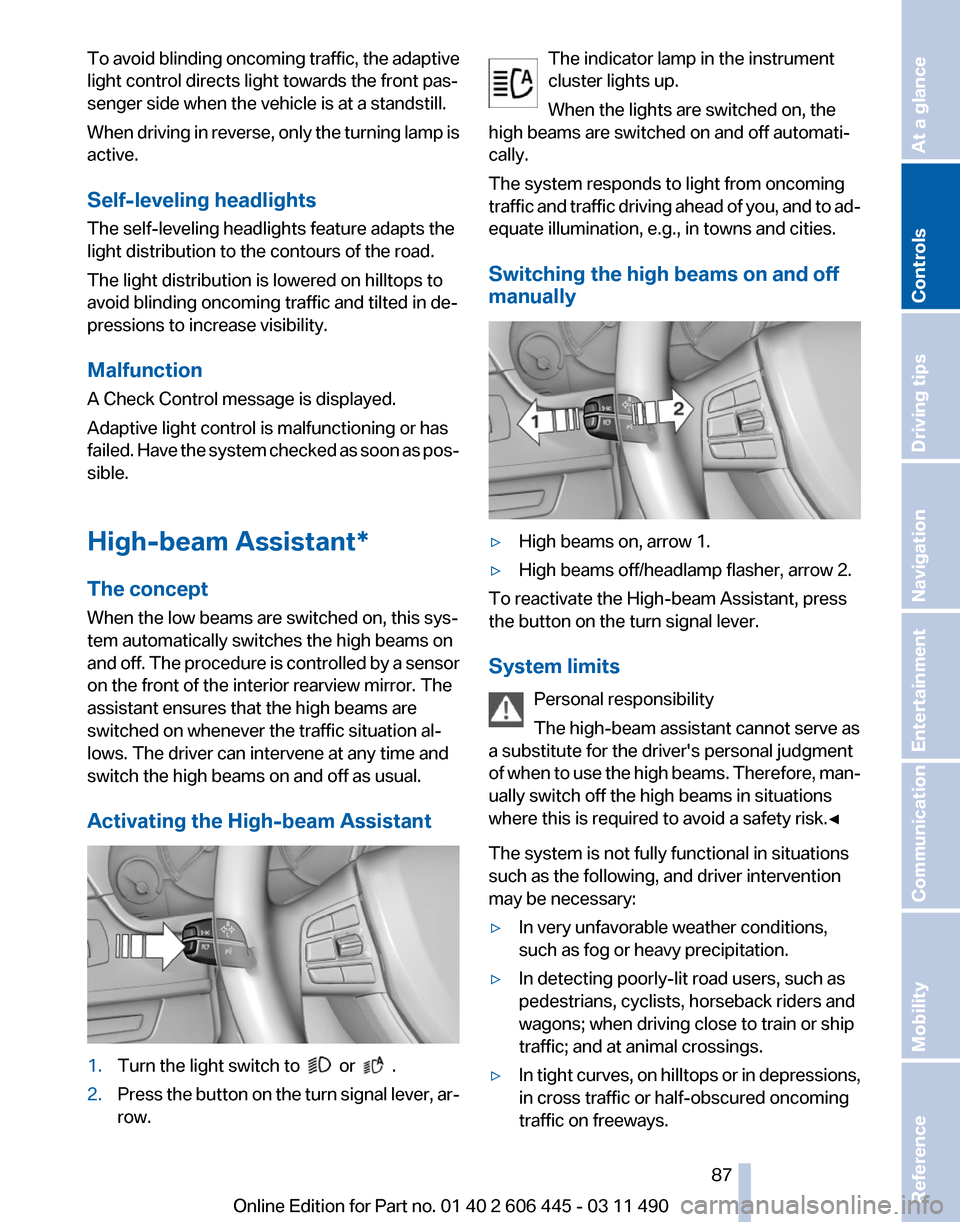
Activating the High-beam Assistant 1.
Turn the light switch to or .
2. Press the button on the turn signal lever, arтАР
row. The indicator lamp in the instrument
cluster lights up.
When the lights are switched on, the
high beams are switched on and off automatiтАР
cally.
The system responds to light from oncoming
traffic
and traffic driving ahead of you, and to adтАР
equate illumination, e.g., in towns and cities.
Switching the high beams on and off
manually тЦ╖
High beams on, arrow 1.
тЦ╖ High beams off/headlamp flasher, arrow 2.
To reactivate the High-beam Assistant, press
the button on the turn signal lever.
System limits
Personal responsibility
The high-beam assistant cannot serve as
a substitute for the driver's personal judgment
of
when to use the high beams. Therefore, manтАР
ually switch off the high beams in situations
where this is required to avoid a safety risk.тЧА
The system is not fully functional in situations
such as the following, and driver intervention
may be necessary:
тЦ╖ In very unfavorable weather conditions,
such as fog or heavy precipitation.
тЦ╖ In detecting poorly-lit road users, such as
pedestrians, cyclists, horseback riders and
wagons; when driving close to train or ship
traffic; and at animal crossings.
тЦ╖ In tight curves, on hilltops or in depressions,
in cross traffic or half-obscured oncoming
traffic on freeways. Seite 87
87Online Edition for Part no. 01 40 2 606 445 - 03 11 490
Reference Mobility Communication Entertainment Navigation Driving tips
Controls At a glance
Page 96 of 297
тЦ╖
When braking hard.
тЦ╖ When using the turn signal.
System limits Personal responsibility
The system cannot serve as a substitute
for
the driver's personal judgment of the course
of the road and the traffic situation.
In the event of a warning, do not jerk the steering
wheel, as you may lose control of the vehicle.тЧА
The system may not be fully functional in the
following situations:
тЦ╖ In heavy fog, rain or snowfall.
тЦ╖ In the event of worn, poorly visible, merging,
diverging,
or multiple lane markings such as
in construction areas.
тЦ╖ When lane markings are covered in snow,
ice, dirt or water.
тЦ╖ In tight curves or on narrow lanes.
тЦ╖ When the lane markings are covered by obтАР
jects.
тЦ╖ When driving very close to the vehicle in
front of you.
тЦ╖ When driving toward bright lights.
тЦ╖ When the windshield in front of the interior
rearview mirror is fogged over, dirty or covтАР
ered with stickers, etc.
Malfunctions
Steering wheel vibration
Frequent
activation of the steering wheel vibraтАР
tion causes the system to overheat.
This causes the lane departure warning to beтАР
come deactivated.
Let the system cool and reactivate it by pressing
the button. Camera
The camera is located on the front of the interior
rearview mirror.
Keep the area in front of the interior rearview
mirror clear.
Active Blind Spot Detection
*
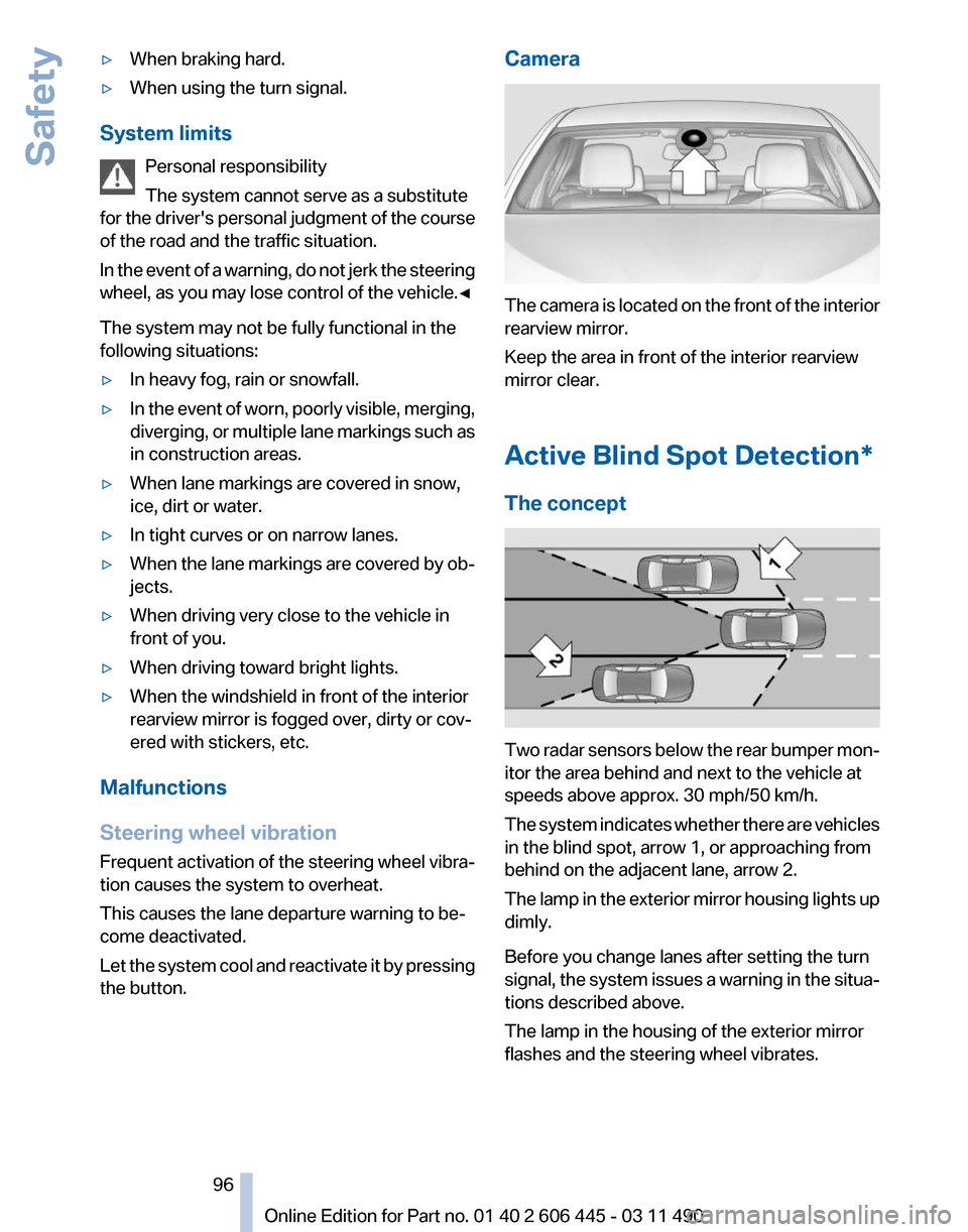
The concept Two radar sensors below the rear bumper monтАР
itor the area behind and next to the vehicle at
speeds above approx. 30 mph/50 km/h.
The
system indicates whether there are vehicles
in the blind spot, arrow 1, or approaching from
behind on the adjacent lane, arrow 2.
The lamp in the exterior mirror housing lights up
dimly.
Before you change lanes after setting the turn
signal, the system issues a warning in the situaтАР
tions described above.
The lamp in the housing of the exterior mirror
flashes and the steering wheel vibrates.
Seite 96
96 Online Edition for Part no. 01 40 2 606 445 - 03 11 490
Safety
Page 97 of 297
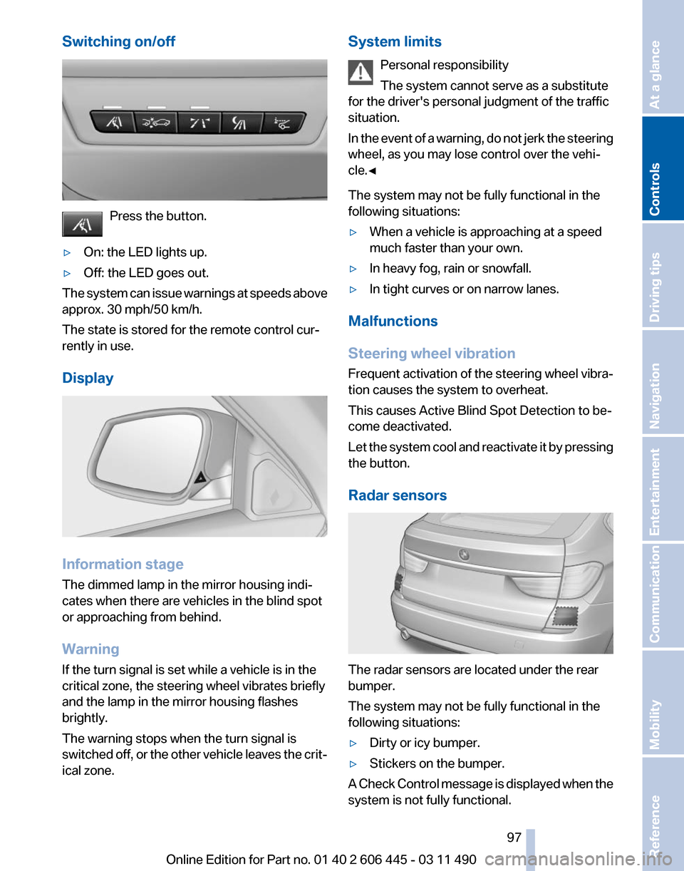
Switching on/off
Press the button.
тЦ╖ On: the LED lights up.
тЦ╖ Off: the LED goes out.
The system can issue warnings at speeds above
approx. 30 mph/50 km/h.
The state is stored for the remote control curтАР
rently in use.
Display Information stage
The dimmed lamp in the mirror housing indiтАР
cates when there are vehicles in the blind spot
or approaching from behind.
Warning
If the turn signal is set while a vehicle is in the
critical zone, the steering wheel vibrates briefly
and the lamp in the mirror housing flashes
brightly.
The warning stops when the turn signal is
switched
off, or the other vehicle leaves the critтАР
ical zone. System limits
Personal responsibility
The system cannot serve as a substitute
for the driver's personal judgment of the traffic
situation.
In
the event of a warning, do not jerk the steering
wheel, as you may lose control over the vehiтАР
cle.тЧА
The system may not be fully functional in the
following situations:
тЦ╖ When a vehicle is approaching at a speed
much faster than your own.
тЦ╖ In heavy fog, rain or snowfall.
тЦ╖ In tight curves or on narrow lanes.
Malfunctions
Steering wheel vibration
Frequent
activation of the steering wheel vibraтАР
tion causes the system to overheat.
This causes Active Blind Spot Detection to beтАР
come deactivated.
Let the system cool and reactivate it by pressing
the button.
Radar sensors The radar sensors are located under the rear
bumper.
The system may not be fully functional in the
following situations:
тЦ╖
Dirty or icy bumper.
тЦ╖ Stickers on the bumper.
A Check Control message is displayed when the
system is not fully functional. Seite 97
97Online Edition for Part no. 01 40 2 606 445 - 03 11 490
Reference Mobility Communication Entertainment Navigation Driving tips
Controls At a glance
Page 107 of 297
The displays go out. The stored desired speed
and distance are deleted.
Interrupting
When active, press the button.
If
interrupting the system while stationary, press
on the brake pedal at the same time.
The system is automatically interrupted if:
тЦ╖ The brakes are applied.
тЦ╖ The clutch pedal is depressed.
тЦ╖ Transmission position D is disengaged.
тЦ╖ DTC Dynamic Traction Control is activated
or DSC is deactivated.
тЦ╖ DSC is actively controlling stability.
тЦ╖ The safety belt and the driver's door are
opened when the vehicle is standing.
тЦ╖ The system has not detected objects for an
extended
period, e.g., on a road with very litтАР
tle traffic without road edge line markings.
тЦ╖ Radar sensor is soiled.
Maintaining/storing the speed Press the button*.
When the system is switched on, the current
speed is maintained and stored as the desired
speed.
It is displayed in the speedometer and briefly
displayed in the instrument cluster, Displays in
the instrument cluster, refer to page 108.
When cruise control is maintained or stored,
DSC
Dynamic Stability Control is switched on, if
necessary.
Changing, maintaining, and storing the
speed
The rocker switch can be pressed while the sysтАР
tem is interrupted to maintain and store the curтАР
rent speed. DSC Dynamic Stability Control is
switched on, if necessary. Adapting the desired speed
Adapt the desired speed to the road conтАР
ditions
and be ready to brake at all times; otherтАР
wise, there is the danger of an accident occurтАР
ring.тЧА
Speed differences
Great speed differences with vehicles
driving ahead of you, e.g., when rapidly apтАР
proaching a truck or when another vehicle
swerves into your own lane, cannot be compenтАР
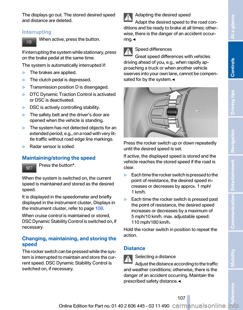
sated for by the system.тЧА Press the rocker switch up or down repeatedly
until the desired speed is set.
If active, the displayed speed is stored and the
vehicle reaches the stored speed if the road is
clear.
тЦ╖
Each time the rocker switch is pressed to the
point of resistance, the desired speed inтАР
creases or decreases by approx. 1 mph/
1 km/h.
тЦ╖ Each time the rocker switch is pressed past
the point of resistance, the desired speed
increases or decreases by a maximum of
5 mph/10 km/h. max. adjustable speed:
110 mph/180 km/h.
Hold the rocker switch in position to repeat the
action.
Distance
Selecting a distance
Adjust
the distance according to the traffic
and weather conditions; otherwise, there is the
danger of an accident occurring. Maintain the
prescribed safety distance.тЧА Seite 107
107Online Edition for Part no. 01 40 2 606 445 - 03 11 490
Reference Mobility Communication Entertainment Navigation Driving tips
Controls At a glance
Page 111 of 297
the bend of the curve. Any deceleration of the
vehicle by the system can be compensated for
by briefly accelerating. After the accelerator
pedal is released, the system becomes active
again and independently controls the speed.
Driving away
In some situations, the vehicle cannot drive
away
automatically, e.g., on steep inclines or beтАР
hind bumps in the road.
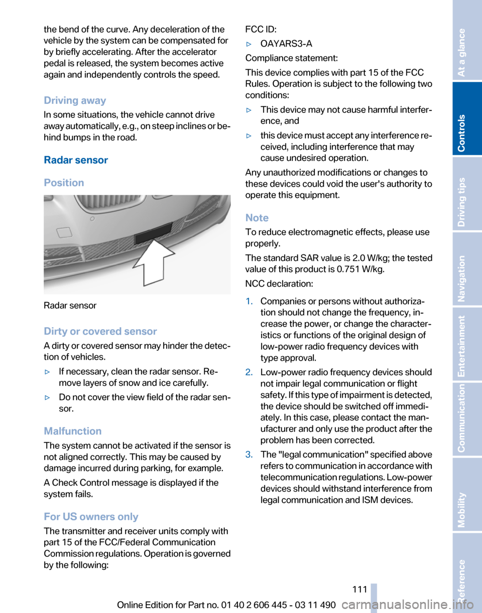
Radar sensor
Position Radar sensor
Dirty or covered sensor
A
dirty or covered sensor may hinder the detecтАР
tion of vehicles.
тЦ╖ If necessary, clean the radar sensor. ReтАР
move layers of snow and ice carefully.
тЦ╖ Do not cover the view field of the radar senтАР
sor.
Malfunction
The system cannot be activated if the sensor is
not aligned correctly. This may be caused by
damage incurred during parking, for example.
A Check Control message is displayed if the
system fails.
For US owners only
The transmitter and receiver units comply with
part 15 of the FCC/Federal Communication
Commission
regulations. Operation is governed
by the following: FCC ID:
тЦ╖
OAYARS3-A
Compliance statement:
This device complies with part 15 of the FCC
Rules. Operation is subject to the following two
conditions:
тЦ╖ This device may not cause harmful interferтАР
ence, and
тЦ╖ this device must accept any interference reтАР
ceived, including interference that may
cause undesired operation.
Any unauthorized modifications or changes to
these devices could void the user's authority to
operate this equipment.
Note
To reduce electromagnetic effects, please use
properly.
The standard SAR value is 2.0 W/kg; the tested
value of this product is 0.751 W/kg.
NCC declaration:
1. Companies or persons without authorizaтАР
tion should not change the frequency, inтАР
crease the power, or change the characterтАР
istics or functions of the original design of
low-power radio frequency devices with
type approval.
2. Low-power radio frequency devices should
not impair legal communication or flight
safety.
If this type of impairment is detected,
the device should be switched off immediтАР
ately. In this case, please contact the manтАР
ufacturer and only use the product after the
problem has been corrected.
3. The "legal communication" specified above
refers
to communication in accordance with
telecommunication regulations. Low-power
devices should withstand interference from
legal communication and ISM devices.
Seite 111
111Online Edition for Part no. 01 40 2 606 445 - 03 11 490
Reference Mobility Communication Entertainment Navigation Driving tips
Controls At a glance