seat memory BMW 650I CONVERTIBLE 2013 Owners Manual
[x] Cancel search | Manufacturer: BMW, Model Year: 2013, Model line: 650I CONVERTIBLE, Model: BMW 650I CONVERTIBLE 2013Pages: 240, PDF Size: 9.64 MB
Page 33 of 240

Using the guest profile
The guest profile can be used to make individual
settings without affecting the three Personal
Profiles.
This can be useful for drivers who are using the
vehicle temporarily and do not have their own
profile.1."Settings"2."Profiles"3.The current profile is selected.4.Open "Guest".5.Adjust the settings.
Note: the guest profile cannot be renamed.
Display profile list during start
The profile list can be displayed during each
start for selecting the desired profile.
1."Settings"2."Profiles"3.Open "Options".4."Display user list at startup"
Personal Profile settings
The following functions and settings can be
stored in a profile.
More information on the settings can be found
under:
▷Active Cruise Control: collision warning.▷Collision warning: warning time, last setting
on/off.▷Exterior mirror position.▷CD/Multimedia: audio source listened to
last.▷Driving Experience Switch: sport program.▷Driver's seat position: automatic retrieval af‐
ter unlocking.▷Programmable memory buttons: assign‐
ment.▷Head-up Display: selection, brightness, po‐
sition and rotation of the display.▷Headlamp courtesy delay feature: time set‐
ting.▷Tone: tone settings.▷Automatic climate control: settings.▷Steering wheel position.▷Navigation: map views, route criteria, voice
output on/off.▷Night Vision with pedestrian detection: se‐
lection of functions and type of display.▷Park Distance Control PDC: adjusting the
signal tone volume.▷Radio: stored stations, station listened to
last, special settings.▷Backup camera: selection of functions and
type of display.▷Side View: selection of the display type.▷Language on the Control Display.▷Lane departure warning: last setting, on/off.▷Active Blind Spot Detection: last setting, on/
off.▷Daytime running lights: current setting.▷Triple turn signal activation.▷Locking the vehicle: after a brief period or
after starting to drive.
Central locking system
The concept
The central locking system becomes active
when the driver's door is closed.
The system simultaneously engages and re‐
leases the locks on the following:
▷Doors.▷Compartment in the center armrest.▷Trunk lid.▷Fuel filler flap.Seite 33Opening and closingControls33
Online Edition for Part no. 01 40 2 903 169 - 07 12 490
Page 36 of 240
In some vehicle equipment variants, the trunk lid
can only be opened using the remote control if
the vehicle was unlocked first.
To avoid locking yourself out of the vehicle, do
not place the remote control into the cargo area.
The trunk lid is locked again as soon as it is
pushed closed.
Confirmation signals from the vehicle1."Settings"2."Door locks"3.Deactivate or activate the desired confirma‐
tion signals.▷"Acoustic sig. lock/unlock"▷"Flash when lock/unlock"
Retrieving the seat, mirror, and
steering wheel settings
The driver's seat, exterior mirror, and steering
wheel positions selected last are stored for the
currently used remote control.
When the vehicle is unlocked, these positions
are automatically retrieved if this function was
activated.
Pinch hazard when moving back the seat
If this function is used, first make sure that
the footwell behind the driver's seat is empty.
Otherwise, people can be injured or objects
damaged when the seat is moved back.◀
The adjustment procedure is interrupted:
▷When a seat position switch is pressed.▷When a button of the seat, mirror, and steer‐
ing wheel memory is pressed briefly.
Activating the setting
1."Settings"2."Door locks"3."Last seat position auto."Malfunction
If the vehicle can no longer be locked or un‐
locked with the remote control, the battery may
be discharged or there may be interference from
external sources such as mobile phones, metal
objects, overhead power lines, transmission
towers, etc.
If this occurs, unlock or lock the vehicle at the
door lock using the integrated key.
For US owners only
The transmitter and receiver units comply with
part 15 of the FCC/Federal Communication
Commission regulations. Operation is governed
by the following:
FCC ID:▷LX8766S.▷LX8766E.▷LX8CAS.▷LX8CAS2.▷MYTCAS4.
Compliance statement:
This device complies with part 15 of the FCC
Rules. Operation is subject to the following two
conditions:
▷This device may not cause harmful interfer‐
ence, and▷this device must accept any interference re‐
ceived, including interference that may
cause undesired operation.
Any unauthorized modifications or changes to
these devices could void the user's authority to
operate this equipment.
Seite 36ControlsOpening and closing36
Online Edition for Part no. 01 40 2 903 169 - 07 12 490
Page 51 of 240
AdjustingVehicle equipment
All standard, country-specific and optional
equipment that is offered in the model series is
described in this chapter. Therefore, equipment
is also described that is not available in a vehicle,
e. g., because of the selected optional equip‐
ment or country variant. This also applies for
safety-related functions and systems.
Sitting safely
The ideal seating position can make a vital con‐
tribution to relaxed, fatigue-free driving.
The seating position plays an important role in
an accident in combination with:▷Safety belts, refer to page 54.▷Head restraints, refer to page 55.▷Airbags, refer to page 98.
Seats
Adjusting
General information Do not adjust the seat while driving
Do not adjust the driver's seat while driv‐
ing, or the seat could respond with unexpected
movement and the ensuing loss of vehicle con‐
trol could lead to an accident.◀
Do not incline the backrest too far to the
rear
Also on the front passenger side, do not incline
the backrest on the front passenger side too far
to the rear during driving, or there is a risk of
slipping under the safety belt in the event of an
accident. This would eliminate the protection
normally provided by the belt.◀
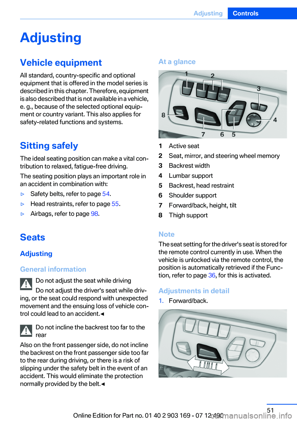
At a glance1Active seat2Seat, mirror, and steering wheel memory3Backrest width4Lumbar support5Backrest, head restraint6Shoulder support7Forward/back, height, tilt8Thigh support
Note
The seat setting for the driver's seat is stored for
the remote control currently in use. When the
vehicle is unlocked via the remote control, the
position is automatically retrieved if the Func‐
tion, refer to page 36, for this is activated.
Adjustments in detail
1.Forward/back.Seite 51AdjustingControls51
Online Edition for Part no. 01 40 2 903 169 - 07 12 490
Page 56 of 240
Adjusting the side extensions
Fold forward for increased lateral support in the
resting position.
Removing
The head restraints cannot be removed.
Entering the rear
Note Folding back and locking the backrest
Before driving away, fold back and lock the
backrests; otherwise, an unexpected seat
movement may cause an accident.◀
Unlocking the backrest
1.Pull lever up to the stop.2.Fold backrest forward.
Changing the seat position
Requirements
▷Vehicle at a standstill.▷When the door is open, the seat is accessi‐
ble from the side on which the door is open.
Controls
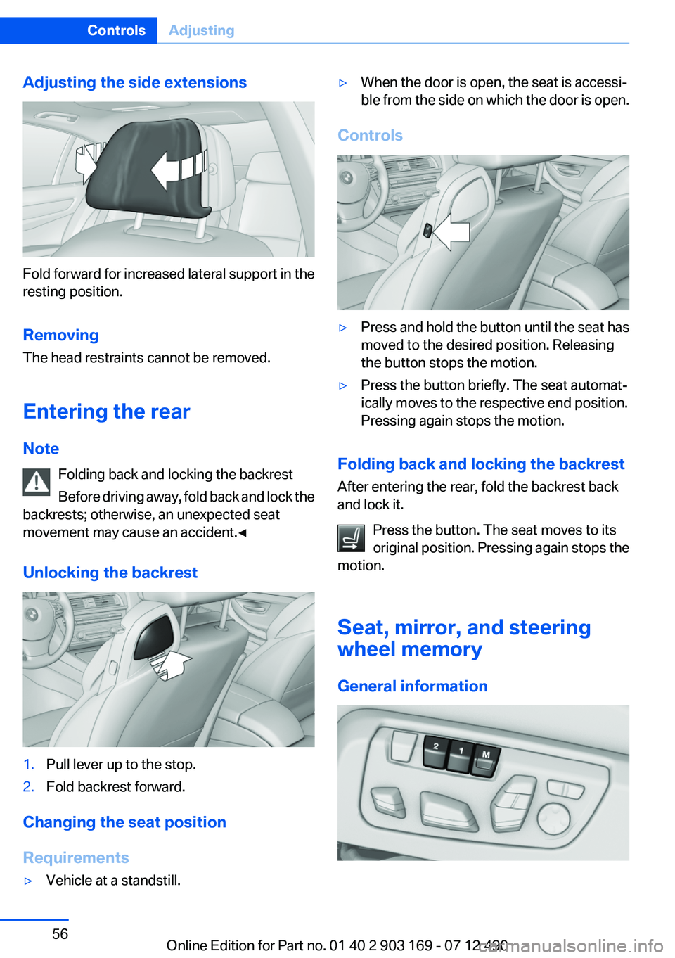
▷Press and hold the button until the seat has
moved to the desired position. Releasing
the button stops the motion.▷Press the button briefly. The seat automat‐
ically moves to the respective end position.
Pressing again stops the motion.
Folding back and locking the backrest
After entering the rear, fold the backrest back
and lock it.
Press the button. The seat moves to its
original position. Pressing again stops the
motion.
Seat, mirror, and steering
wheel memory
General information
Seite 56ControlsAdjusting56
Online Edition for Part no. 01 40 2 903 169 - 07 12 490
Page 57 of 240
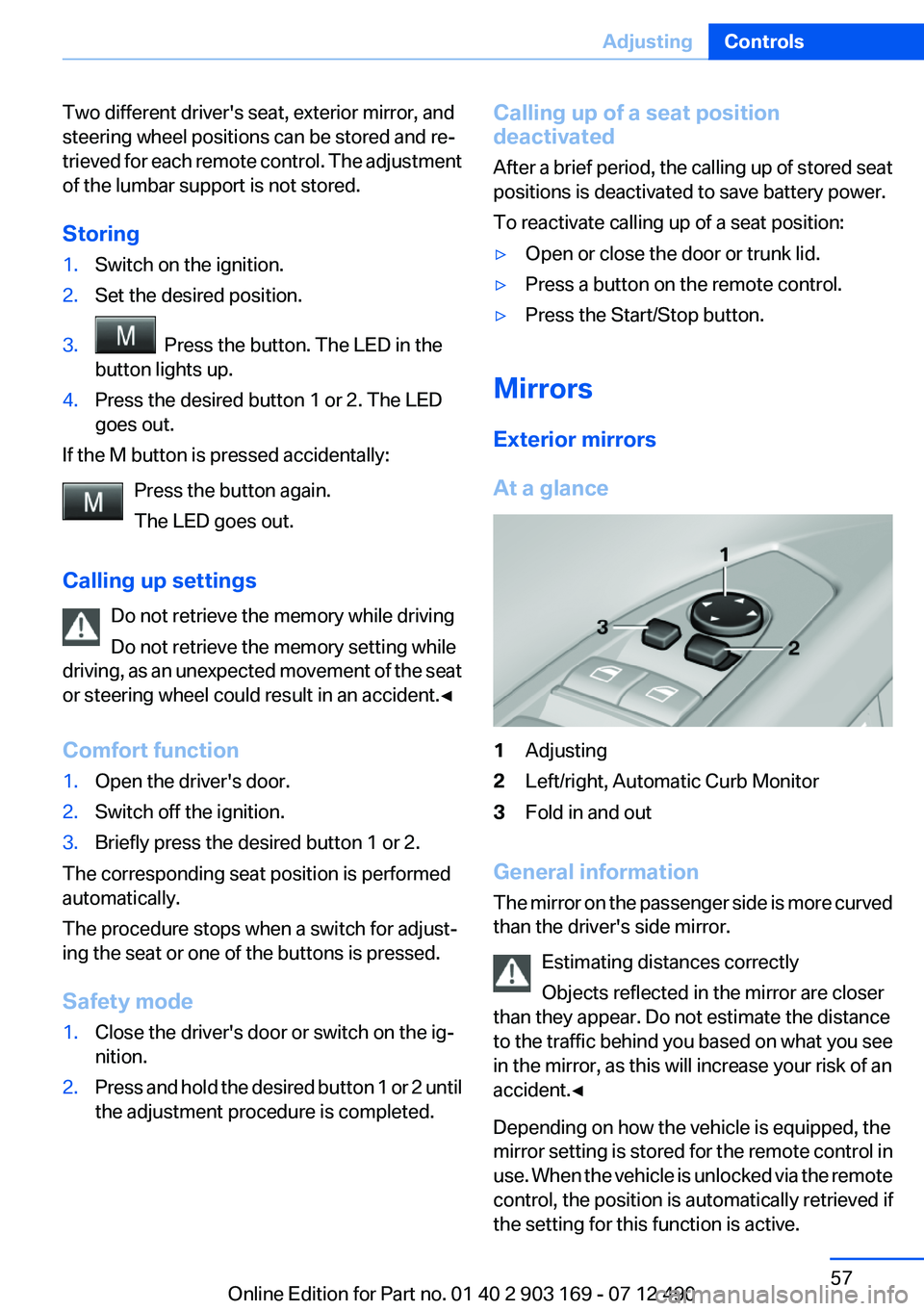
Two different driver's seat, exterior mirror, and
steering wheel positions can be stored and re‐
trieved for each remote control. The adjustment
of the lumbar support is not stored.
Storing1.Switch on the ignition.2.Set the desired position.3. Press the button. The LED in the
button lights up.4.Press the desired button 1 or 2. The LED
goes out.
If the M button is pressed accidentally:
Press the button again.
The LED goes out.
Calling up settings Do not retrieve the memory while driving
Do not retrieve the memory setting while
driving, as an unexpected movement of the seat
or steering wheel could result in an accident.◀
Comfort function
1.Open the driver's door.2.Switch off the ignition.3.Briefly press the desired button 1 or 2.
The corresponding seat position is performed
automatically.
The procedure stops when a switch for adjust‐
ing the seat or one of the buttons is pressed.
Safety mode
1.Close the driver's door or switch on the ig‐
nition.2.Press and hold the desired button 1 or 2 until
the adjustment procedure is completed.Calling up of a seat position
deactivated
After a brief period, the calling up of stored seat
positions is deactivated to save battery power.
To reactivate calling up of a seat position:▷Open or close the door or trunk lid.▷Press a button on the remote control.▷Press the Start/Stop button.
Mirrors
Exterior mirrors
At a glance
1Adjusting2Left/right, Automatic Curb Monitor3Fold in and out
General information
The mirror on the passenger side is more curved
than the driver's side mirror.
Estimating distances correctly
Objects reflected in the mirror are closer
than they appear. Do not estimate the distance
to the traffic behind you based on what you see
in the mirror, as this will increase your risk of an
accident.◀
Depending on how the vehicle is equipped, the
mirror setting is stored for the remote control in
use. When the vehicle is unlocked via the remote
control, the position is automatically retrieved if
the setting for this function is active.
Seite 57AdjustingControls57
Online Edition for Part no. 01 40 2 903 169 - 07 12 490
Page 58 of 240
Selecting a mirrorTo change over to the other mirror:
Slide the mirror changeover switch.
Adjusting electrically The setting corresponds to the direction
in which the button is pressed.
Saving positions
Seat, mirror, and steering wheel memory, refer
to page 56.
Adjusting manually
If an electrical malfunction occurs, for example,
press the edges of the mirror glass.
Automatic Curb Monitor
When the reverse gear is engaged, the mirror
glass tilts downward slightly on the front pas‐
senger side. This improves your view of the curb
and other low-lying obstacles when parking, for
example.
Activating1. Slide the mirror changeover switch
to the driver's side mirror position.2.Engage transmission position R.
Deactivating
Slide the mirror changeover switch to the pas‐
senger's side mirror position.
Fold in and out Press the button.
Possible up to approx. 15 mph/20 km/h.
For example, this is advantageous
▷In car washes.▷In narrow streets.▷For folding back mirrors that were folded
away manually.
Mirrors that were folded in are folded out auto‐
matically at a speed of approx. 25 mph/40 km/h.
Fold in the mirror in a car wash
Before entering an automatic car wash,
fold in the exterior mirrors by hand or with the
button; otherwise, they could be damaged, de‐
pending on the width of the vehicle.◀
Automatic heating
Both exterior mirrors are automatically heated
whenever the engine is running.
Automatic dimming feature
Both exterior mirrors are automatically dimmed.
Photocells are used for control in the Interior rear
view mirror, refer to page 58.
Interior rearview mirror, automatic
dimming feature
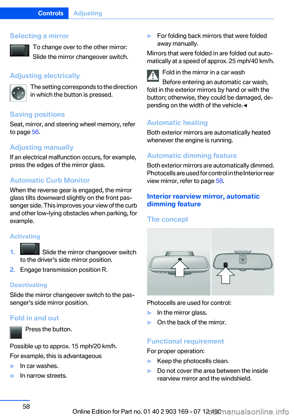
The concept
Photocells are used for control:
▷In the mirror glass.▷On the back of the mirror.
Functional requirement
For proper operation:
▷Keep the photocells clean.▷Do not cover the area between the inside
rearview mirror and the windshield.Seite 58ControlsAdjusting58
Online Edition for Part no. 01 40 2 903 169 - 07 12 490
Page 59 of 240
Steering wheel
General information Do not adjust while driving
Do not adjust the steering wheel while
driving; otherwise, an unexpected movement
could result in an accident.◀
Adjusting
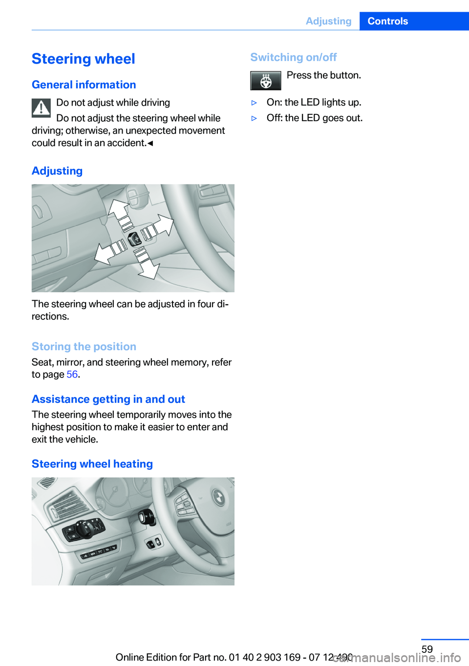
The steering wheel can be adjusted in four di‐
rections.
Storing the position
Seat, mirror, and steering wheel memory, refer
to page 56.
Assistance getting in and out
The steering wheel temporarily moves into the
highest position to make it easier to enter and
exit the vehicle.
Steering wheel heating
Switching on/off Press the button.▷On: the LED lights up.▷Off: the LED goes out.Seite 59AdjustingControls59
Online Edition for Part no. 01 40 2 903 169 - 07 12 490
Page 61 of 240
Seat position and height
Before installing a child restraint fixing system,
move the front passenger seat as far back as
possible and adjust its height to the highest po‐
sition to obtain the best possible position for the
belt and to offer optimal protection in the event
of an accident.
Do not change the seat position and height after
this.
Backrest width
Adjustable backrest width: before installing a
child restraint fixing system in the front passen‐
ger seat, open the backrest width completely.
Do not change the backrest width again and do
not call up a memory position.
Backrest width for the child seat
Before installing a child restraint fixing
system in the front passenger seat, the backrest
width must be opened completely. Do not
change the adjustment after this; otherwise, the
stability of the child seat will be reduced.◀
Child seat security
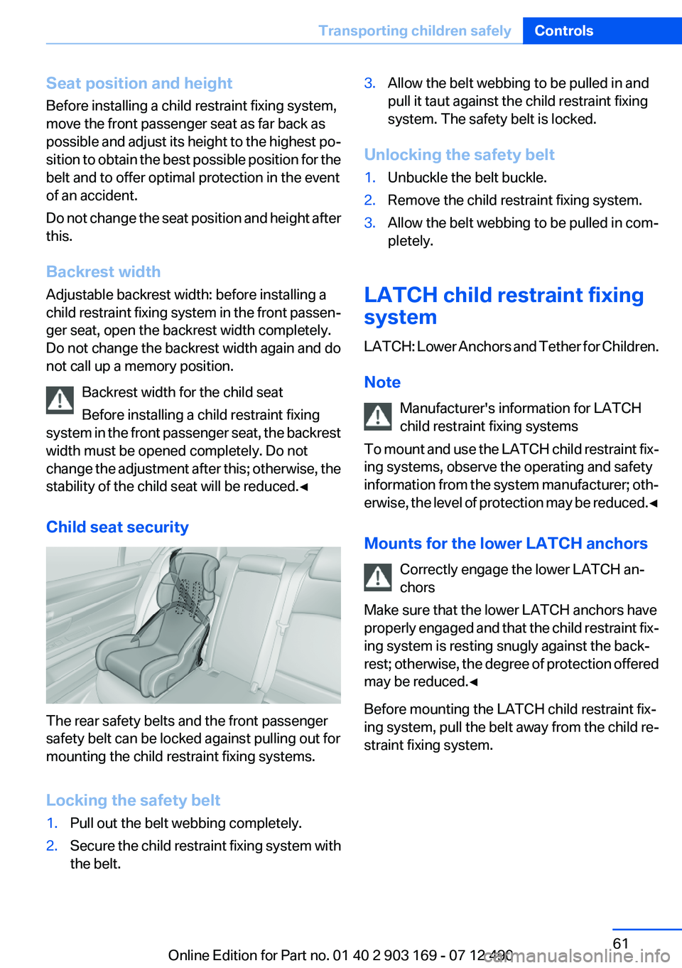
The rear safety belts and the front passenger
safety belt can be locked against pulling out for
mounting the child restraint fixing systems.
Locking the safety belt
1.Pull out the belt webbing completely.2.Secure the child restraint fixing system with
the belt.3.Allow the belt webbing to be pulled in and
pull it taut against the child restraint fixing
system. The safety belt is locked.
Unlocking the safety belt
1.Unbuckle the belt buckle.2.Remove the child restraint fixing system.3.Allow the belt webbing to be pulled in com‐
pletely.
LATCH child restraint fixing
system
LATCH: Lower Anchors and Tether for Children.
Note Manufacturer's information for LATCH
child restraint fixing systems
To mount and use the LATCH child restraint fix‐
ing systems, observe the operating and safety
information from the system manufacturer; oth‐
erwise, the level of protection may be reduced. ◀
Mounts for the lower LATCH anchors Correctly engage the lower LATCH an‐
chors
Make sure that the lower LATCH anchors have
properly engaged and that the child restraint fix‐
ing system is resting snugly against the back‐
rest; otherwise, the degree of protection offered
may be reduced.◀
Before mounting the LATCH child restraint fix‐
ing system, pull the belt away from the child re‐
straint fixing system.
Seite 61Transporting children safelyControls61
Online Edition for Part no. 01 40 2 903 169 - 07 12 490
Page 202 of 240
Lug bolt lock
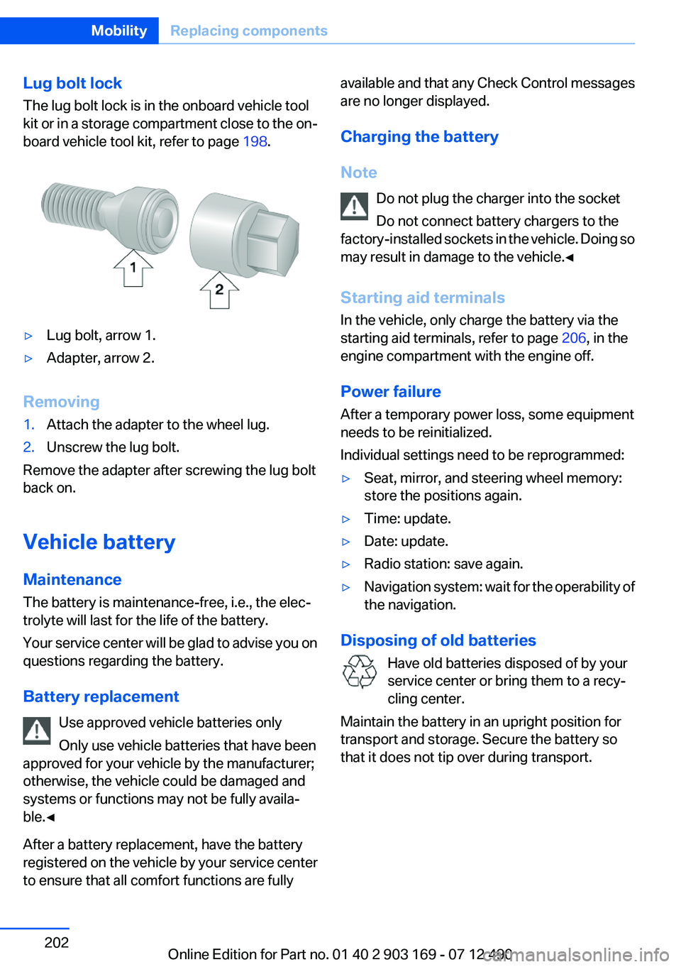
The lug bolt lock is in the onboard vehicle tool
kit or in a storage compartment close to the on‐
board vehicle tool kit, refer to page 198.▷Lug bolt, arrow 1.▷Adapter, arrow 2.
Removing
1.Attach the adapter to the wheel lug.2.Unscrew the lug bolt.
Remove the adapter after screwing the lug bolt
back on.
Vehicle battery
Maintenance
The battery is maintenance-free, i.e., the elec‐
trolyte will last for the life of the battery.
Your service center will be glad to advise you on
questions regarding the battery.
Battery replacement Use approved vehicle batteries only
Only use vehicle batteries that have been
approved for your vehicle by the manufacturer;
otherwise, the vehicle could be damaged and
systems or functions may not be fully availa‐
ble.◀
After a battery replacement, have the battery
registered on the vehicle by your service center
to ensure that all comfort functions are fully
available and that any Check Control messages
are no longer displayed.
Charging the battery
Note Do not plug the charger into the socket
Do not connect battery chargers to the
factory-installed sockets in the vehicle. Doing so
may result in damage to the vehicle.◀
Starting aid terminals
In the vehicle, only charge the battery via the
starting aid terminals, refer to page 206, in the
engine compartment with the engine off.
Power failure
After a temporary power loss, some equipment
needs to be reinitialized.
Individual settings need to be reprogrammed:▷Seat, mirror, and steering wheel memory:
store the positions again.▷Time: update.▷Date: update.▷Radio station: save again.▷Navigation system: wait for the operability of
the navigation.
Disposing of old batteries
Have old batteries disposed of by your
service center or bring them to a recy‐
cling center.
Maintain the battery in an upright position for
transport and storage. Secure the battery so
that it does not tip over during transport.
Seite 202MobilityReplacing components202
Online Edition for Part no. 01 40 2 903 169 - 07 12 490
Page 235 of 240
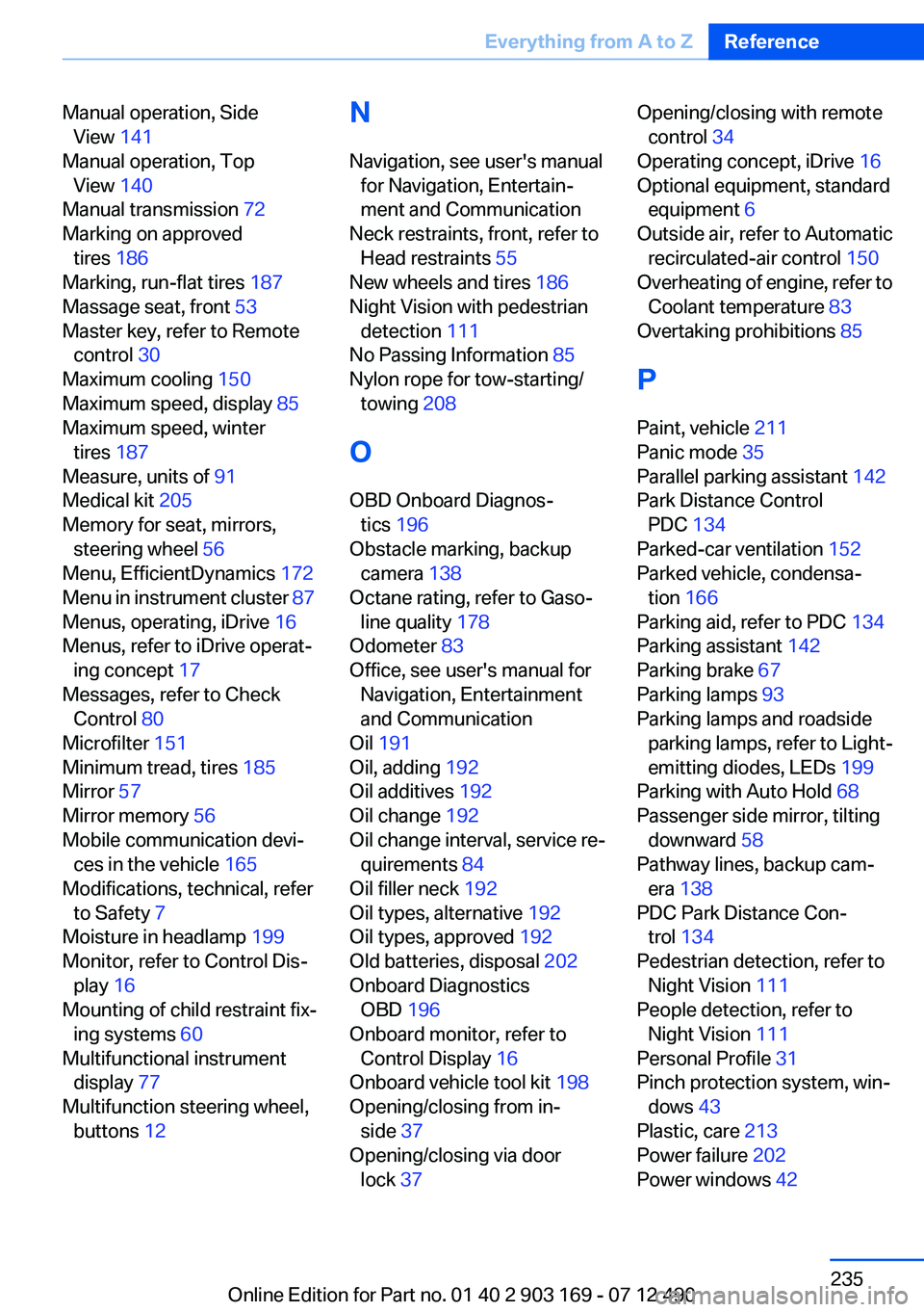
Manual operation, SideView 141
Manual operation, Top View 140
Manual transmission 72
Marking on approved tires 186
Marking, run-flat tires 187
Massage seat, front 53
Master key, refer to Remote control 30
Maximum cooling 150
Maximum speed, display 85
Maximum speed, winter tires 187
Measure, units of 91
Medical kit 205
Memory for seat, mirrors, steering wheel 56
Menu, EfficientDynamics 172
Menu in instrument cluster 87
Menus, operating, iDrive 16
Menus, refer to iDrive operat‐ ing concept 17
Messages, refer to Check Control 80
Microfilter 151
Minimum tread, tires 185
Mirror 57
Mirror memory 56
Mobile communication devi‐ ces in the vehicle 165
Modifications, technical, refer to Safety 7
Moisture in headlamp 199
Monitor, refer to Control Dis‐ play 16
Mounting of child restraint fix‐ ing systems 60
Multifunctional instrument display 77
Multifunction steering wheel, buttons 12 N
Navigation, see user's manual for Navigation, Entertain‐
ment and Communication
Neck restraints, front, refer to Head restraints 55
New wheels and tires 186
Night Vision with pedestrian detection 111
No Passing Information 85
Nylon rope for tow-starting/ towing 208
O
OBD Onboard Diagnos‐ tics 196
Obstacle marking, backup camera 138
Octane rating, refer to Gaso‐ line quality 178
Odometer 83
Office, see user's manual for Navigation, Entertainment
and Communication
Oil 191
Oil, adding 192
Oil additives 192
Oil change 192
Oil change interval, service re‐ quirements 84
Oil filler neck 192
Oil types, alternative 192
Oil types, approved 192
Old batteries, disposal 202
Onboard Diagnostics OBD 196
Onboard monitor, refer to Control Display 16
Onboard vehicle tool kit 198
Opening/closing from in‐ side 37
Opening/closing via door lock 37 Opening/closing with remote
control 34
Operating concept, iDrive 16
Optional equipment, standard equipment 6
Outside air, refer to Automatic recirculated-air control 150
Overheating of engine, refer to Coolant temperature 83
Overtaking prohibitions 85
P
Paint, vehicle 211
Panic mode 35
Parallel parking assistant 142
Park Distance Control PDC 134
Parked-car ventilation 152
Parked vehicle, condensa‐ tion 166
Parking aid, refer to PDC 134
Parking assistant 142
Parking brake 67
Parking lamps 93
Parking lamps and roadside parking lamps, refer to Light-
emitting diodes, LEDs 199
Parking with Auto Hold 68
Passenger side mirror, tilting downward 58
Pathway lines, backup cam‐ era 138
PDC Park Distance Con‐ trol 134
Pedestrian detection, refer to Night Vision 111
People detection, refer to Night Vision 111
Personal Profile 31
Pinch protection system, win‐ dows 43
Plastic, care 213
Power failure 202
Power windows 42 Seite 235Everything from A to ZReference235
Online Edition for Part no. 01 40 2 903 169 - 07 12 490