AUX BMW 740IL 2001 E38 Level Control System Manual
[x] Cancel search | Manufacturer: BMW, Model Year: 2001, Model line: 740IL, Model: BMW 740IL 2001 E38Pages: 57, PDF Size: 1.89 MB
Page 28 of 57

28
Level Control Systems
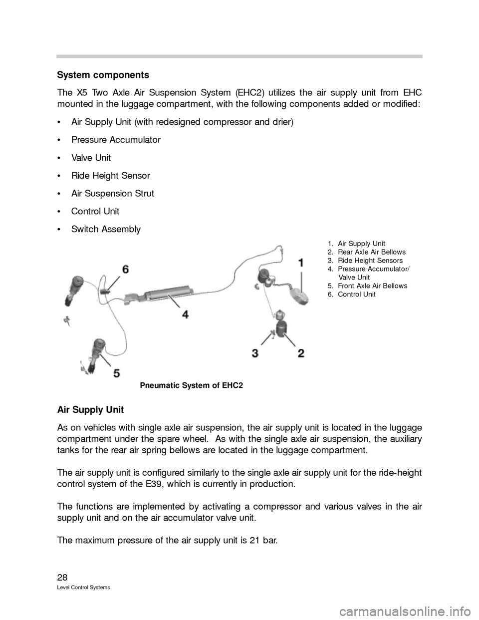
System components
The X5 Two Axle Air Suspension System (EHC2) utilizes the air supply unit from EHC
mounted in the luggage compartment, with the following components added or modified:
Air Supply Unit (with redesigned compressor and drier)
Pressure Accumulator
Valve Unit
Ride Height Sensor
Air Suspension Strut
Control Unit
Switch Assembly
Air Supply Unit
As on vehicles with single axle air suspension, the air supply unit is located in the luggage
compartment under the spare wheel. As with the single axle air suspension, the auxiliary
tanks for the rear air spring bellows are located in the luggage compartment.
The air supply unit is configured similarly to the single axle air supply unit for the ride-height
control system of the E39, which is currently in production.
The functions are implemented by activating a compressor and various valves in the air
supply unit and on the air accumulator valve unit.
The maximum pressure of the air supply unit is 21 bar.
1. Air Supply Unit
2. Rear Axle Air Bellows
3. Ride Height Sensors
4. Pressure Accumulator/
Valve Unit
5. Front Axle Air Bellows
6. Control Unit
Pneumatic System of EHC2
Page 33 of 57

33
Level Control Systems
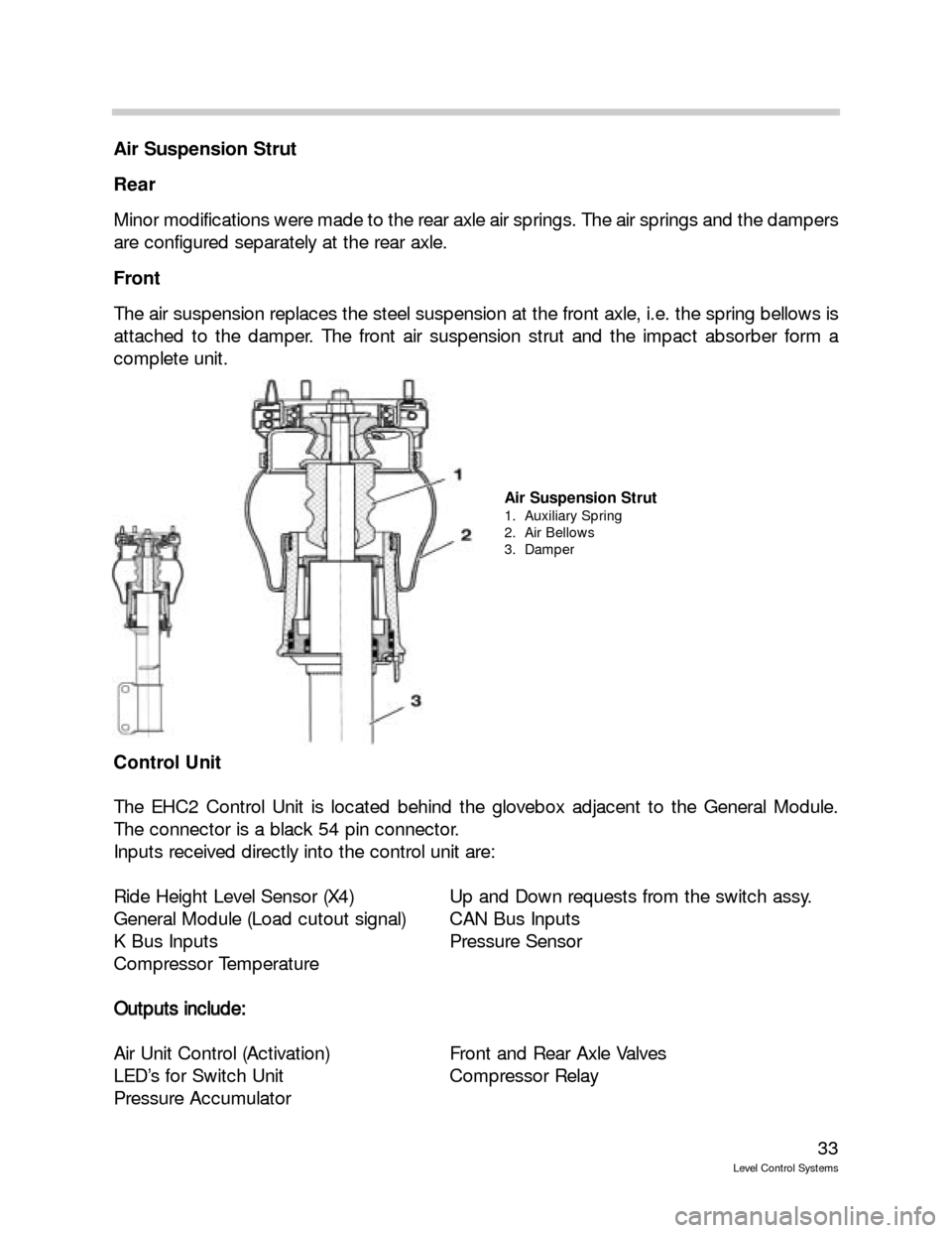
Air Suspension Strut
Rear
Minor modifications were made to the rear axle air springs. The air springs and the dampers
are configured separately at the rear axle.
Front
The air suspension replaces the steel suspension at the front axle, i.e. the spring bellows is
attached to the damper. The front air suspension strut and the impact absorber form a
complete unit.
Control Unit
The EHC2 Control Unit is located behind the glovebox adjacent to the General Module.
The connector is a black 54 pin connector.
Inputs received directly into the control unit are:
Ride Height Level Sensor (X4) Up and Down requests from the switch assy.
General Module (Load cutout signal) CAN Bus Inputs
K Bus Inputs Pressure Sensor
Compressor Temperature
O Ou
ut
tp
pu
ut
ts
s
i
in
nc
cl
lu
ud
de
e:
:
Air Unit Control (Activation) Front and Rear Axle Valves
LED’s for Switch Unit Compressor Relay
Pressure Accumulator
Air Suspension Strut
1. Auxiliary Spring
2. Air Bellows
3. Damper
Page 37 of 57

37
Level Control Systems
In addition to the LED indicator, the following text messages can
be displayed in the instrument cluster:
T TR
RA
AI
IL
LE
ER
R
M
MO
OD
DE
E
A coupled trailer is identified via the trailer connector. To avoid damaging the trailer and
the vehicle, changes of vehicle level are generally avoided. The standard level is "frozen."
If the trailer is coupled at a level other than the Standard level, the vehicle ride level is
not changed to Standard unless a button is pressed or the speed threshold for auto-
matic change-over is reached. The standard level is then "frozen" until the trailer con-
nector is disconnected.
R RI
ID
DE
E
H
HE
EI
IG
GH
HT
T
C
CO
ON
NT
TR
RO
OL
L
I
IN
NA
AC
CT
TI
IV
VE
E
Faults in the system and on the control unit which are only identified by the instrument
cluster, e.g. control unit disconnected
R RI
ID
DE
E
H
HE
EI
IG
GH
HT
T
C
CO
ON
NT
TR
RO
OL
L
I
IN
NA
AC
CT
TI
IV
VE
E
+
+
M
MA
AX
X.
.
6
60
0
k
km
m/
/h
h
For safety-critical faults (vehicle is too high or at inclination)
Control Modes
Sleep mode
If the vehicle is parked, it enters Sleep mode after 16 minutes. No further control opera-
tions are executed. A "watch dog" wakes up the control unit for a few minutes every 6
hours (wakeup mode) in order to compensate for possible inclination of the vehicle. (Vehicle
height may only be corrected once as air supply unit only operates with engine running.)
Wake-up
In wake-up mode, the control unit is woken up for a set period of time in order to com-
pensate for possible inclination of the vehicle. Inclination of the vehicle can be caused by
large temperature differences or by minor leaks. Adjustments to the front and rear axles
ensure that the vehicle is visually level. To minimize power consumption, the vehicle is low-
ered only. The nominal level of the lowest wheel serves as the nominal level for all other
wheels. The lowest nominal level to which the vehicle is lowered is the Access level (-35
mm).
Exception:if the vehicle is parked at Access level, the vehicle is lowered to max. -50 mm
in wake-up mode. If the vehicle is parked for a prolonged period of time and there is a leak
in the system, further loss of pressure does not produce a change of ride level since the
weight of the body is born by the auxiliary suspension and the residual tire pressure.
Advance /Overrun
When the vehicle is woken out of sleep mode by the load-cutout signal (VA), it normally
enters advance / overrun mode. Since the engine is not (no longer) running in this mode,
however, there are restrictions on the control operations that can be performed in order to
conserve the battery. Ride level compensation is restricted to tolerance ranges of 20 mm
and 25 mm in the up and down directions respectively. This serves to reduce the frequen-
cy of control operations.