manual BMW 740LI 2011 F02 Owner's Guide
[x] Cancel search | Manufacturer: BMW, Model Year: 2011, Model line: 740LI, Model: BMW 740LI 2011 F02Pages: 299, PDF Size: 8.49 MB
Page 83 of 299
message and the meaning of the indicator and
warning lamps.
Supplementary text messages
Addition information, such as on the cause of a
fault or the required action, can be called up via
Check Control. The supplementary text of ur‐
gent messages is displayed automatically.
It is shown on the Control Display.
Symbols
Depending on the Check Control message, the
following functions can be selected.
▷
"Owner's Manual"
Display additional information about the
Check Control message in the integrated
owner's manual.
▷ "Service request"
Contact the service partner.
▷ "Roadside Assistance"
Contact Roadside Assistance.
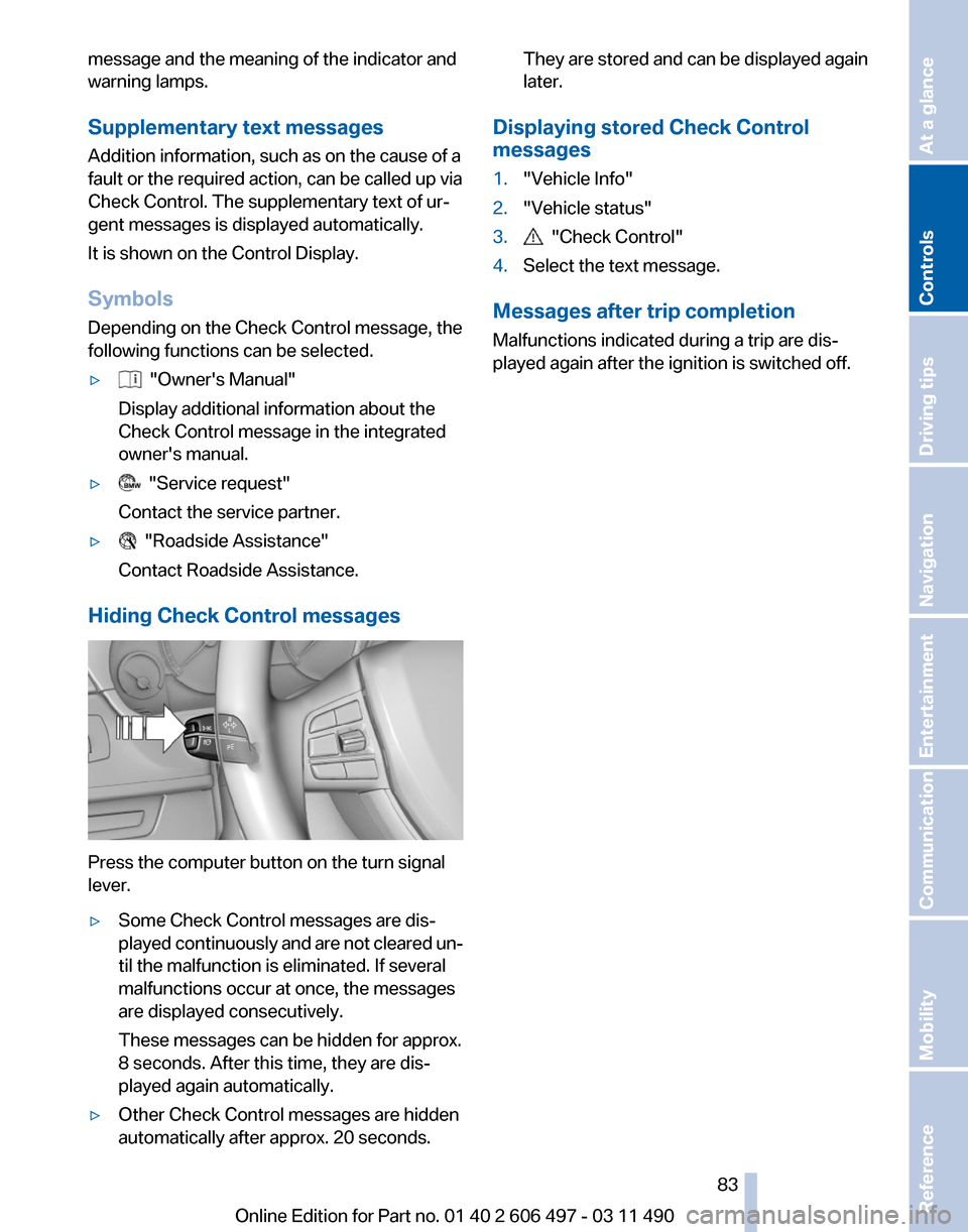
Hiding Check Control messages Press the computer button on the turn signal
lever.
▷
Some Check Control messages are dis‐
played
continuously and are not cleared un‐
til the malfunction is eliminated. If several
malfunctions occur at once, the messages
are displayed consecutively.
These messages can be hidden for approx.
8 seconds. After this time, they are dis‐
played again automatically.
▷ Other Check Control messages are hidden
automatically after approx. 20 seconds. They are stored and can be displayed again
later.
Displaying stored Check Control
messages
1. "Vehicle Info"
2. "Vehicle status"
3. "Check Control"
4. Select the text message.
Messages after trip completion
Malfunctions indicated during a trip are dis‐
played again after the ignition is switched off.
Seite 83
83Online Edition for Part no. 01 40 2 606 497 - 03 11 490
Reference Mobility Communication Entertainment Navigation Driving tips
Controls At a glance
Page 85 of 299
The setting is stored for the remote control cur‐
rently in use.
Automatic headlamp control
Switch
position : the low beams are switched
on and off automatically, e.g., in tunnels, in twi‐
light or if there is precipitation. The indicator
lamp in the instrument cluster lights up.
A blue sky with the sun low on the horizon can
cause the lights to be switched on.
The low beams always stay on when the fog
lamps are switched on.
Personal responsibility
The automatic headlamp control cannot
serve
as a substitute for your personal judgment
in determining when the lamps should be
switched on in response to ambient lighting
conditions.
For example, the sensors are unable to detect
fog or hazy weather. To avoid safety risks, you
should always switch on the lamps manually un‐
der these conditions.◀
Daytime running lights*
With the ignition switched on, the daytime run‐
ning lights light up in position 0, or .
After the ignition is switched off, the parking
lamps light up in position
.
Activating/deactivating
1. "Settings"
2. "Lighting"
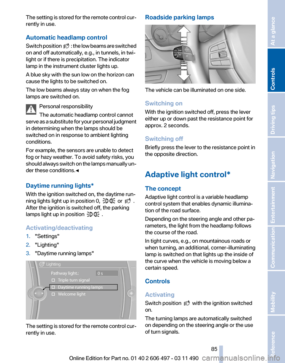
3. "Daytime running lamps" The setting is stored for the remote control cur‐
rently in use. Roadside parking lamps
The vehicle can be illuminated on one side.
Switching on
With the ignition switched off, press the lever
either up or down past the resistance point for
approx. 2 seconds.
Switching off
Briefly press the lever to the resistance point in
the opposite direction.
Adaptive light control*
The concept
Adaptive light control is a variable headlamp
control system that enables dynamic illumina‐
tion of the road surface.
Depending on the steering angle and other pa‐
rameters, the light from the headlamp follows
the course of the road.
In tight curves, e.g., on mountainous roads or
when turning, an additional, corner-illuminating
lamp is switched on that lights up the inside of
the curve when the vehicle is moving below a
certain speed.
Controls
Activating
Switch position
with the ignition switched
on.
The turning lamps are automatically switched
on depending on the steering angle or the use
of turn signals.
Seite 85
85Online Edition for Part no. 01 40 2 606 497 - 03 11 490
Reference Mobility Communication Entertainment Navigation Driving tips
Controls At a glance
Page 86 of 299
To avoid blinding oncoming traffic, the adaptive
light control directs light towards the front pas‐
senger side when the vehicle is at a standstill.
When
driving in reverse, only the turning lamp is
active.
Self-leveling headlights
The self-leveling headlights feature adapts the
light distribution to the contours of the road.
The light distribution is lowered on hilltops to
avoid blinding oncoming traffic and tilted in de‐
pressions to increase visibility.
Malfunction
A Check Control message is displayed.
Adaptive light control is malfunctioning or has
failed. Have the system checked as soon as pos‐
sible.
High-beam Assistant*
The concept
When the low beams are switched on, this sys‐
tem automatically switches the high beams on
and off. The procedure is controlled by a sensor
on the front of the interior rearview mirror. The
assistant ensures that the high beams are
switched on whenever the traffic situation al‐
lows. The driver can intervene at any time and
switch the high beams on and off as usual.
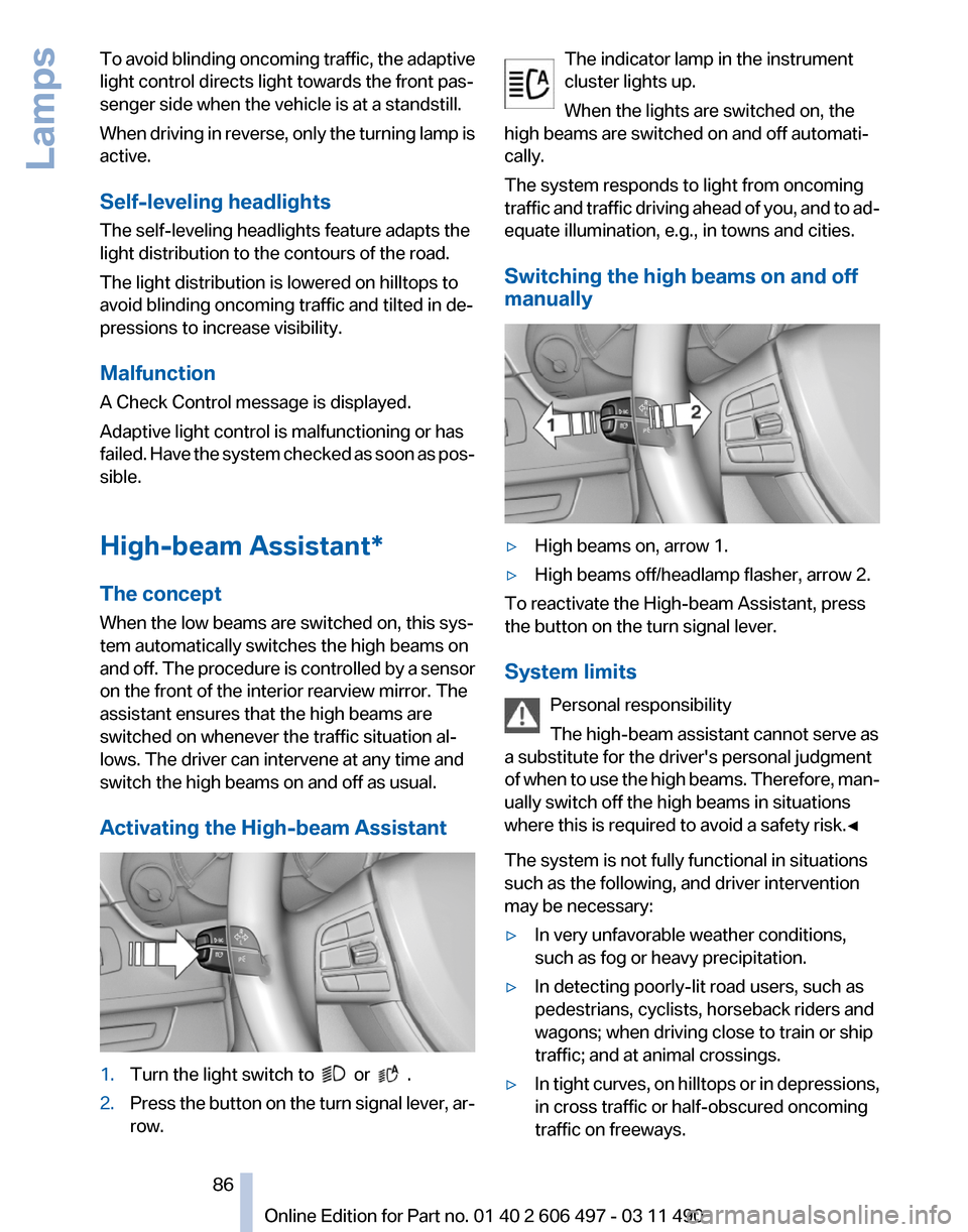
Activating the High-beam Assistant 1.
Turn the light switch to or .
2. Press the button on the turn signal lever, ar‐
row. The indicator lamp in the instrument
cluster lights up.
When the lights are switched on, the
high beams are switched on and off automati‐
cally.
The system responds to light from oncoming
traffic
and traffic driving ahead of you, and to ad‐
equate illumination, e.g., in towns and cities.
Switching the high beams on and off
manually ▷
High beams on, arrow 1.
▷ High beams off/headlamp flasher, arrow 2.
To reactivate the High-beam Assistant, press
the button on the turn signal lever.
System limits
Personal responsibility
The high-beam assistant cannot serve as
a substitute for the driver's personal judgment
of
when to use the high beams. Therefore, man‐
ually switch off the high beams in situations
where this is required to avoid a safety risk.◀
The system is not fully functional in situations
such as the following, and driver intervention
may be necessary:
▷ In very unfavorable weather conditions,
such as fog or heavy precipitation.
▷ In detecting poorly-lit road users, such as
pedestrians, cyclists, horseback riders and
wagons; when driving close to train or ship
traffic; and at animal crossings.
▷ In tight curves, on hilltops or in depressions,
in cross traffic or half-obscured oncoming
traffic on freeways. Seite 86
86 Online Edition for Part no. 01 40 2 606 497 - 03 11 490
Lamps
Page 114 of 299
cle with your own eyes. Otherwise, an accident
could result from road users or objects located
outside of the PDC detection range.
Loud
noises from outside and inside the vehicle
may prevent you from hearing the PDC's signal
tone.◀
Avoid driving quickly with PDC
Avoid approaching an object quickly.
Avoid driving away quickly while PDC is not yet
active.
For technical reasons, the system may other‐
wise be too late in issuing a warning.◀
Limits of ultrasonic measurement
The detection of objects can reach the physical
limits of ultrasonic measurement, for instance:
▷ With tow bars and trailer hitches.
▷ With thin or wedge-shaped objects.
▷ With low objects.
▷ With objects with corners and sharp edges.
Low objects already displayed, e.g., curbs, can
move
into the blind area of the sensors before or
after a continuous tone sounds.
High, protruding objects such as ledges may not
be detected.
False warnings
PDC may issue a warning under the following
conditions even though there is no obstacle
within the detection range:
▷ In heavy rain.
▷ When sensors are very dirty or covered in
ice.
▷ When sensors are covered in snow.
▷ On rough road surfaces.
▷ In large buildings with right angles and
smooth
walls, e.g., in underground garages.
▷ In heavy exhaust.
▷ Due to other ultrasound sources, e.g.,
sweeping machines, high pressure steam
cleaners or neon lights. Switching on automatically
Select transmission position R with the engine
running.
Switching off automatically
The
system switches off and the LED goes out:
▷ After approx. 160 ft/50 m when driving for‐
ward.
▷ Above approx. 22 mph/36 km/h when driv‐
ing forward.
Switch on the system again if necessary.
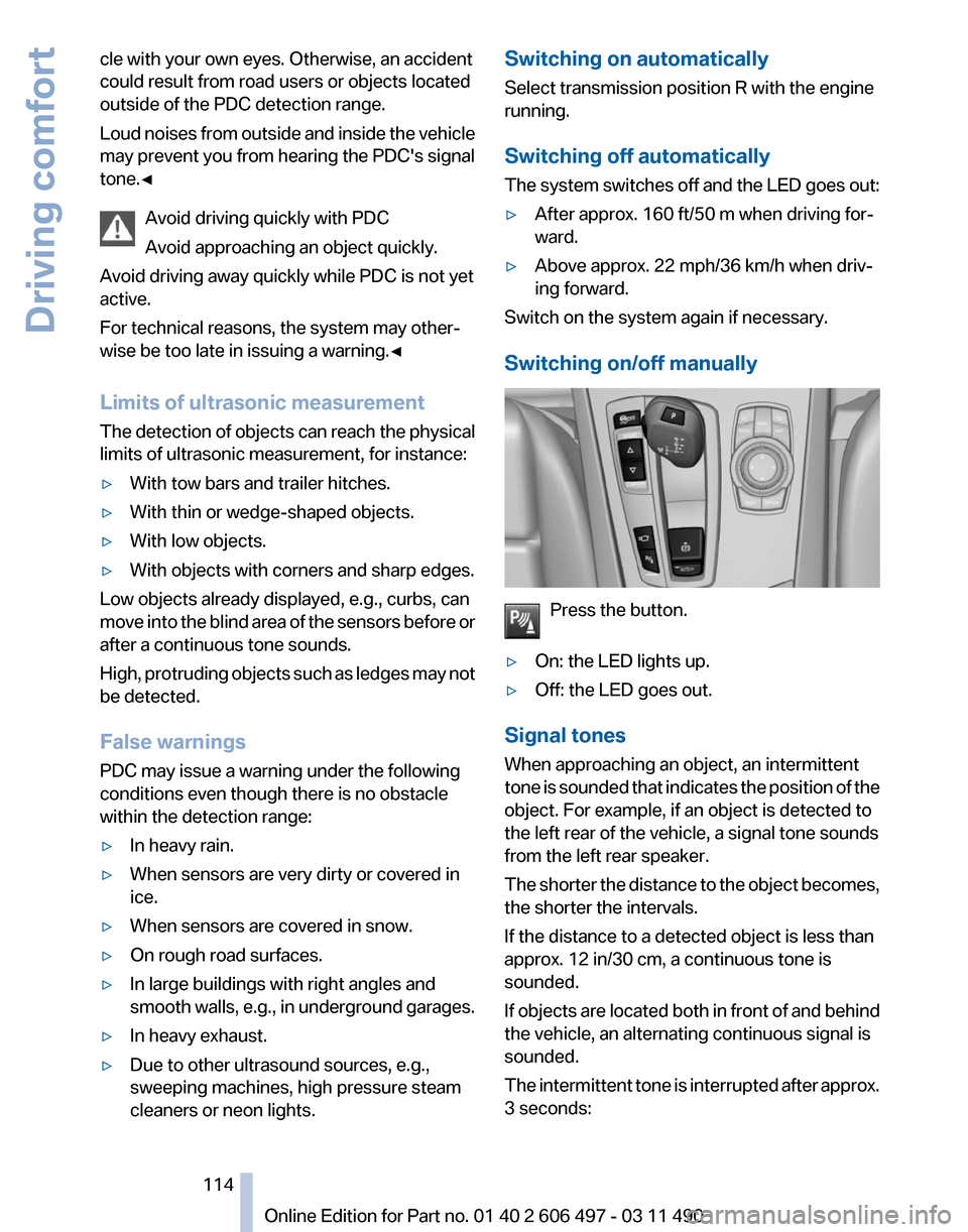
Switching on/off manually Press the button.
▷ On: the LED lights up.
▷ Off: the LED goes out.
Signal tones
When approaching an object, an intermittent
tone
is sounded that indicates the position of the
object. For example, if an object is detected to
the left rear of the vehicle, a signal tone sounds
from the left rear speaker.
The shorter the distance to the object becomes,
the shorter the intervals.
If the distance to a detected object is less than
approx. 12 in/30 cm, a continuous tone is
sounded.
If objects are located both in front of and behind
the vehicle, an alternating continuous signal is
sounded.
The intermittent tone is interrupted after approx.
3 seconds: Seite 114
114 Online Edition for Part no. 01 40 2 606 497 - 03 11 490
Driving comfort
Page 116 of 299
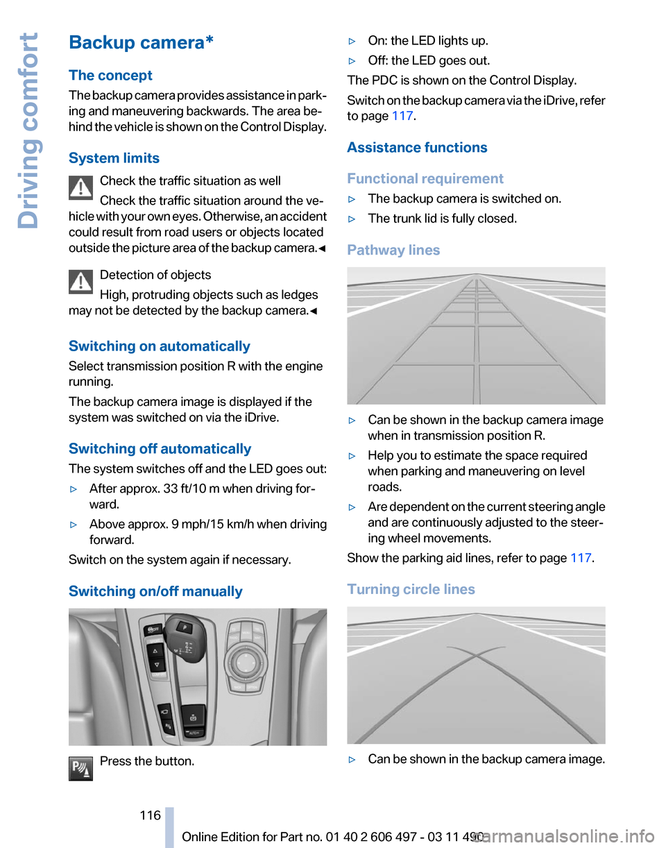
Backup camera*
The concept
The
backup camera provides assistance in park‐
ing and maneuvering backwards. The area be‐
hind the vehicle is shown on the Control Display.
System limits
Check the traffic situation as well
Check the traffic situation around the ve‐
hicle with your own eyes. Otherwise, an accident
could result from road users or objects located
outside the picture area of the backup camera.◀
Detection of objects
High, protruding objects such as ledges
may not be detected by the backup camera.◀
Switching on automatically
Select transmission position R with the engine
running.
The backup camera image is displayed if the
system was switched on via the iDrive.
Switching off automatically
The system switches off and the LED goes out:
▷ After approx. 33 ft/10 m when driving for‐
ward.
▷ Above approx. 9 mph/15 km/h when driving
forward.
Switch on the system again if necessary.
Switching on/off manually Press the button. ▷
On: the LED lights up.
▷ Off: the LED goes out.
The PDC is shown on the Control Display.
Switch
on the backup camera via the iDrive, refer
to page 117.
Assistance functions
Functional requirement
▷ The backup camera is switched on.
▷ The trunk lid is fully closed.
Pathway lines ▷
Can be shown in the backup camera image
when in transmission position R.
▷ Help you to estimate the space required
when parking and maneuvering on level
roads.
▷ Are dependent on the current steering angle
and are continuously adjusted to the steer‐
ing wheel movements.
Show the parking aid lines, refer to page 117.
Turning circle lines ▷
Can be shown in the backup camera image.
Seite 116
116 Online Edition for Part no. 01 40 2 606 497 - 03 11 490
Driving comfort
Page 118 of 299
Camera
The camera lens is located in the handle of the
trunk lid. The image quality may be impaired by
dirt.
Clean the lens, refer to page
273.
Side View*
The concept
Side View provides an early look at cross traffic
at
blind driveways and intersections. Road users
concealed by obstacles to the left and right of
the vehicle can only be detected relatively late
from the driver's seat. To improve visibility, two
cameras in the front of the vehicle record the
traffic situation on each side.
System limits
The maximum recording range of the camera is
330 ft/100 m.
Display
The images from both cameras are shown si‐
multaneously on the Control Display.
Check the traffic situation as well
Check the traffic situation around the ve‐
hicle on blind driveways and intersections with
your own eyes. Otherwise, an accident could re‐
sult from road users or objects located outside
the picture area of the Side View cameras.◀
Switching off automatically
System switches off: above approx. 9 mph/
15 km/h.
Switch on the system again if necessary. Switching on/off manually
Press the button.
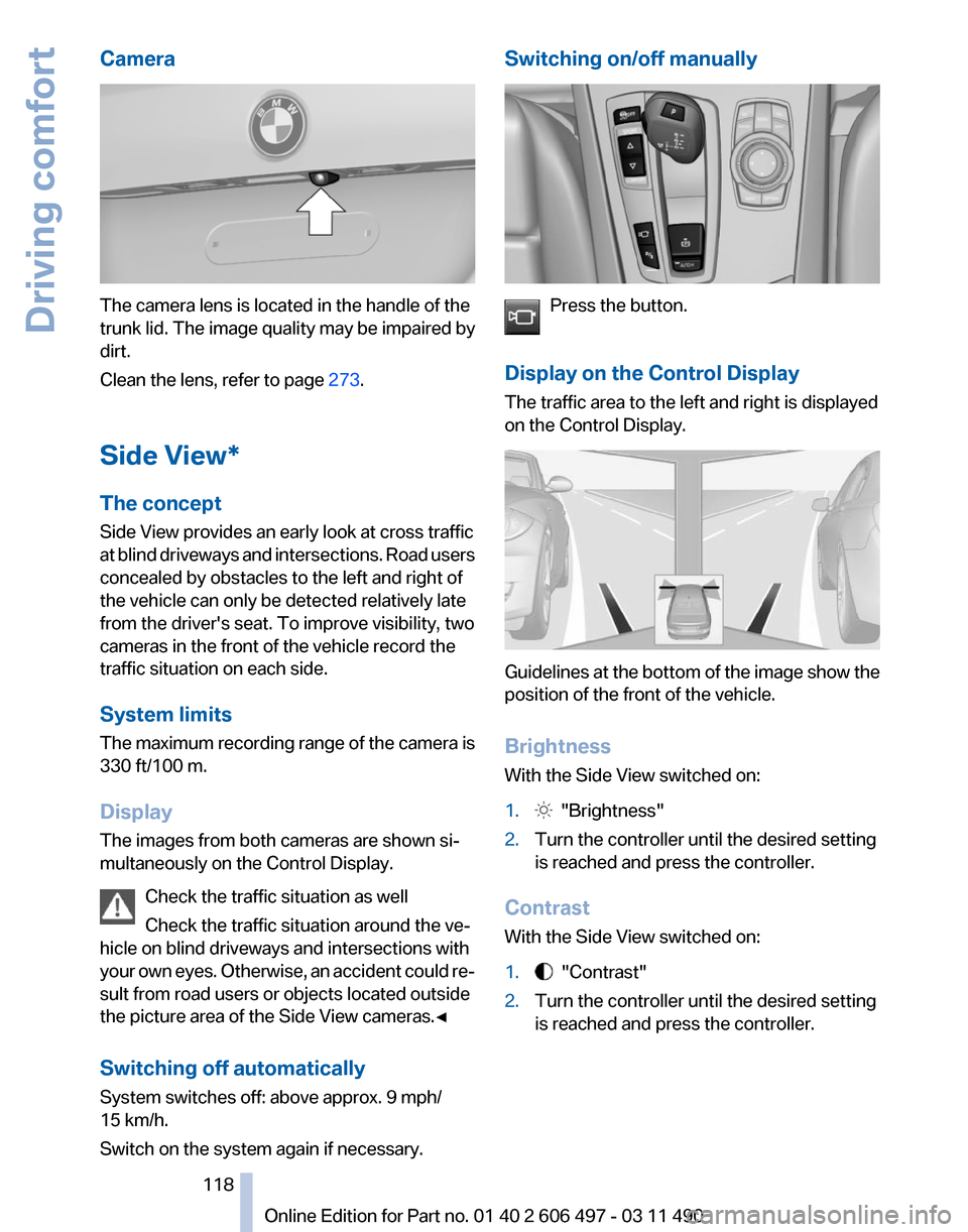
Display on the Control Display
The traffic area to the left and right is displayed
on the Control Display. Guidelines at the bottom of the image show the
position of the front of the vehicle.
Brightness
With the Side View switched on:
1.
"Brightness"
2. Turn the controller until the desired setting
is reached and press the controller.
Contrast
With the Side View switched on:
1. "Contrast"
2. Turn the controller until the desired setting
is reached and press the controller. Seite 118
118 Online Edition for Part no. 01 40 2 606 497 - 03 11 490
Driving comfort
Page 119 of 299
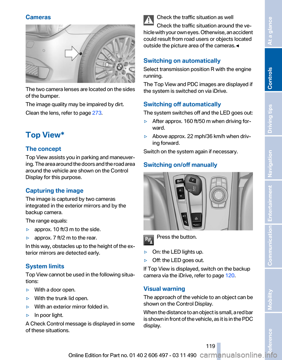
Cameras
The two camera lenses are located on the sides
of the bumper.
The image quality may be impaired by dirt.
Clean the lens, refer to page
273.
Top View*
The concept
Top
View assists you in parking and maneuver‐
ing. The area around the doors and the road area
around the vehicle are shown on the Control
Display for this purpose.
Capturing the image
The image is captured by two cameras
integrated in the exterior mirrors and by the
backup camera.
The range equals:
▷ approx. 10 ft/3 m to the side.
▷ approx. 7 ft/2 m to the rear.
In this way, obstacles up to the height of the ex‐
terior mirrors are detected early.
System limits
Top
View cannot be used in the following situa‐
tions:
▷ With a door open.
▷ With the trunk lid open.
▷ With an exterior mirror folded in.
▷ In poor light.
A Check Control message is displayed in some
of these situations. Check the traffic situation as well
Check the traffic situation around the ve‐
hicle
with your own eyes. Otherwise, an accident
could result from road users or objects located
outside the picture area of the cameras.◀
Switching on automatically
Select transmission position R with the engine
running.
The Top View and PDC images are displayed if
the system is switched on via iDrive.
Switching off automatically
The system switches off and the LED goes out:
▷ After approx. 160 ft/50 m when driving for‐
ward.
▷ Above approx. 22 mph/36 km/h when driv‐
ing forward.
Switch on the system again if necessary.
Switching on/off manually Press the button.
▷ On: the LED lights up.
▷ Off: the LED goes out.
If Top View is displayed, switch on the backup
camera via the iDrive, refer to page 120.
Visual warning
The
approach of the vehicle to an object can be
shown on the Control Display.
When the distance to an object is small, a red bar
is shown in front of the vehicle, as it is in the PDC
display. Seite 119
119Online Edition for Part no. 01 40 2 606 497 - 03 11 490
Reference Mobility Communication Entertainment Navigation Driving tips
Controls At a glance
Page 124 of 299
Press the button.
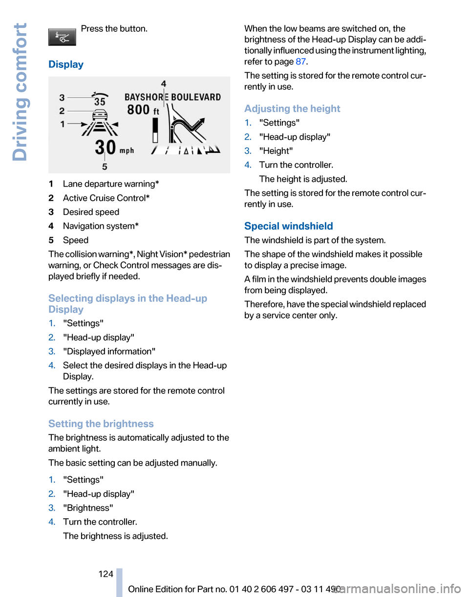
Display 1
Lane departure warning*
2 Active Cruise Control*
3 Desired speed
4 Navigation system*
5 Speed
The collision warning*, Night Vision* pedestrian
warning, or Check Control messages are dis‐
played briefly if needed.
Selecting displays in the Head-up
Display
1. "Settings"
2. "Head-up display"
3. "Displayed information"
4. Select the desired displays in the Head-up
Display.
The settings are stored for the remote control
currently in use.
Setting the brightness
The brightness is automatically adjusted to the
ambient light.
The basic setting can be adjusted manually.
1. "Settings"
2. "Head-up display"
3. "Brightness"
4. Turn the controller.
The brightness is adjusted. When the low beams are switched on, the
brightness
of the Head-up Display can be addi‐
tionally influenced using the instrument lighting,
refer to page 87.
The setting is stored for the remote control cur‐
rently in use.
Adjusting the height
1. "Settings"
2. "Head-up display"
3. "Height"
4. Turn the controller.
The height is adjusted.
The setting is stored for the remote control cur‐
rently in use.
Special windshield
The windshield is part of the system.
The shape of the windshield makes it possible
to display a precise image.
A
film in the windshield prevents double images
from being displayed.
Therefore, have the special windshield replaced
by a service center only.
Seite 124
124 Online Edition for Part no. 01 40 2 606 497 - 03 11 490
Driving comfort
Page 125 of 299
Climate control
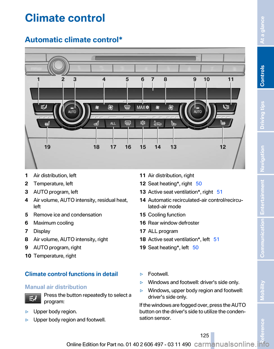
Automatic climate control
*1
Air distribution, left
2 Temperature, left
3 AUTO program, left
4 Air volume, AUTO intensity, residual heat,
left
5 Remove ice and condensation
6 Maximum cooling
7 Display
8 Air volume, AUTO intensity, right
9 AUTO program, right
10 Temperature, right 11
Air distribution, right
12 Seat heating*, right 50
13 Active seat ventilation*, right 51
14 Automatic recirculated-air control/recircu‐
lated-air mode
15 Cooling function
16 Rear window defroster
17 ALL program
18 Active seat ventilation*, left 51
19 Seat heating*, left 50
Climate control functions in detail
Manual air distribution Press the button repeatedly to select a
program:
▷ Upper body region.
▷ Upper body region and footwell. ▷
Footwell.
▷ Windows and footwell: driver's side only.
▷ Windows, upper body region and footwell:
driver's side only.
If the windows are fogged over, press the AUTO
button
on the driver's side to utilize the conden‐
sation sensor.
Seite 125
125Online Edition for Part no. 01 40 2 606 497 - 03 11 490
Reference Mobility Communication Entertainment Navigation Driving tips
Controls At a glance
Page 126 of 299
Temperature
Turn the wheel to set the desired
temperature.
The automatic climate control achieves this
temperature as quickly as possible, if necessary
with the maximum cooling or heating capacity,
and then keeps it constant.
Avoid rapidly switching between different tem‐
perature settings. The automatic climate control
will not have sufficient time to adjust the set
temperature.
AUTO program Press the button.
Air volume, air distribution, and tem‐
perature are controlled automatically.
Depending on the selected temperature, AUTO
intensity, and outside influences, the air is di‐
rected to the windshield, side windows, upper
body, and into the footwell.
The cooling function, refer to page 127, is
switched on automatically with the AUTO pro‐
gram.
At the same time, a condensation sensor con‐
trols the program so as to prevent window con‐
densation as much as possible.
Intensity of the AUTO program
With the AUTO program switched on, automatic
control of the air volume and air distribution can
be adjusted.
Press the left or right side of the button:
decrease or increase the intensity.
The selected intensity is shown on the display
of the automatic climate control.
Air volume, manual
To be able to manually adjust the air volume,
switch off the AUTO program first. Press the left or right side of the button:
decrease or increase air volume. The selected air volume is shown on the display
of the automatic climate control.
The air volume of the automatic climate control
may be reduced automatically to save battery
power.
Defrosting windows and removing
condensation
Press the button.
Ice and condensation are quickly re‐
moved from the windshield and the front side
windows.
The air volume can be adjusted when the pro‐
gram is active.
If the windows are fogged over, additionally
switch on the cooling function or press the
AUTO
button to utilize the condensation sensor.
Maximum cooling Press the button.
The system is set to the lowest tem‐
perature, maximum air volume and recirculated-
air mode.
Air flows out of the vents for the upper body re‐
gion. Open them for this purpose.
Air is cooled as quickly as possible:
▷ At an external temperature of approx. 32 ℉/
0 ℃.
▷ When the engine is running.
The air volume can be adjusted when the pro‐
gram is active.
Automatic recirculated-air control/
recirculated-air mode
You can respond to unpleasant odors or pollu‐
tants in the immediate environment by tempo‐
rarily suspending the supply of outside air. The
system
then recirculates the air currently within
the vehicle.
Press the button repeatedly to select
an operating mode:
▷ LEDs off: outside air flows in continuously. Seite 126
126 Online Edition for Part no. 01 40 2 606 497 - 03 11 490
Climate control