ECU BMW 760Li 2004 E66 User Guide
[x] Cancel search | Manufacturer: BMW, Model Year: 2004, Model line: 760Li, Model: BMW 760Li 2004 E66Pages: 232, PDF Size: 5.27 MB
Page 70 of 232
Driving
68 page 66. We recommend this program for
performance-oriented driving.
When you press the S/M/D button a sec-
ond time the transmission switches to its
manual mode; press again to return to the
automatic program.
You can also return to the standard auto-
matic program by reselecting D.
In the manual mode the transmission
upshifts when you briefly press the buttons
on the rear of the steering wheel. You
downshift by briefly pressing the buttons
on the front of the steering wheel. The Info
Display shows the manual ranges M1
through M6.
Upshifts and downshifts are executed only
when they will result in a plausible combi-
nation of engine and vehicle speed; thus,
for example, a downshift that would cause
the engine to overrev will not be executed
by the system. The selected gear appears
briefly in the Info Display, followed by the
current gear.
To obtain maximum acceleration, for
passing maneuvers, etc., during
operation in the manual mode, use the
kickdown or downshift manually.<
Malfunctions
A status report will appear in the Check
Control to alert you to any malfunctions in
the transmission-control system. Please
note any supplementary information that
appears on the Control Display. The direc-
tional arrows also start to flash in the Info
Display.
While it will remain still possible to move
the selector lever to any desired position,
the transmission will revert to operation in
its default mode with only a limited number
of forward gears.
Some types of malfunction will make it
impossible to engage all gears.
The engine may respond with reduced out-
put when accelerating from a standing
start. If this happens, avoid extreme engine loads
and consult the nearest BMW center.
If no status messages appear in the
Info Display you should accelerate
carefully to confirm that you are driving in
the desired direction.
Never work in the engine compartment
with any of the forward or reverse gears
engaged, as the vehicle could start to
move. Engaging the parking brake, refer to
page 62.<
Manual release of transmission
lockout
You can respond to any interruptions in the
supply of electrical power, for instance, if
the battery is discharged or disconnected,
by releasing the transmission lockout man-
ually.
To prevent the drive wheels from
locking up and sliding, the transmis-
sion lockout must always be released man-
ually before the vehicle is towed.<
Press the brake pedal before releas-
ing the transmission lockout manu-
ally. If the brakes are not applied, the vehi-
cle could start to roll if parked on a steep
slope.
The transmission lockout should only be
released for towing. Remember to engage
the transmission lockout when you repark
the vehicle after moving it.
Should it also be necessary to release
the parking brake manually, owing to a dis-
charged battery, etc., always adhere to the
following sequence:
1.Start by manually releasing the parking
brake, refer to page 64
2.Then proceed to manually release the
transmission lockout.<
Jump-starting and towing, refer to
pages 207 and 208.
Page 85 of 232
Controls
83Reference
At a glance
Driving tips
Communications
Navigation
Entertainment
Mobility
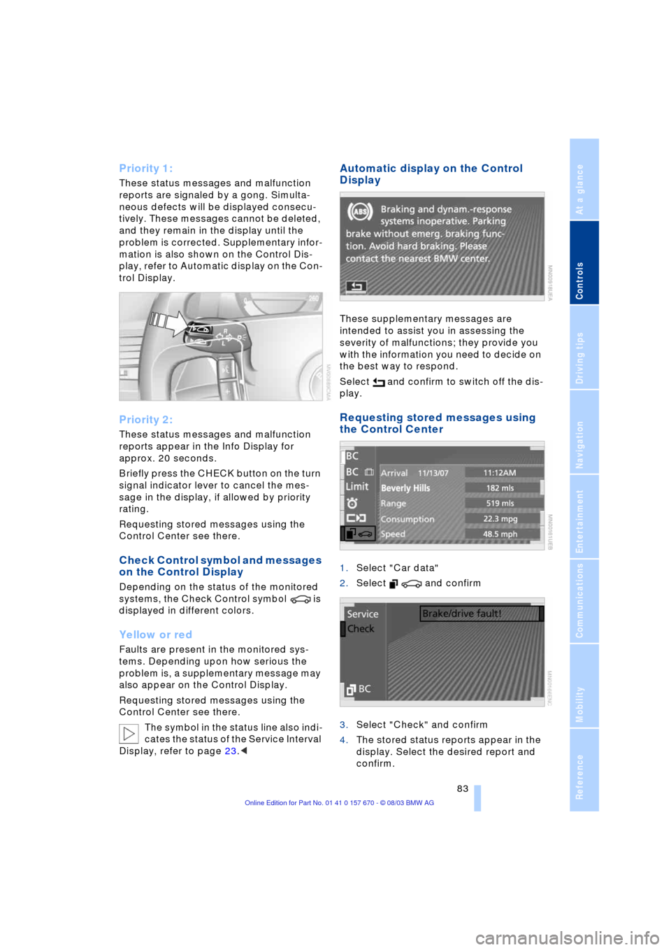
Priority 1:
These status messages and malfunction
reports are signaled by a gong. Simulta-
neous defects will be displayed consecu-
tively. These messages cannot be deleted,
and they remain in the display until the
problem is corrected. Supplementary infor-
mation is also shown on the Control Dis-
play, refer to Automatic display on the Con-
trol Display.
Priority 2:
These status messages and malfunction
reports appear in the Info Display for
approx. 20 seconds.
Briefly press the CHECK button on the turn
signal indicator lever to cancel the mes-
sage in the display, if allowed by priority
rating.
Requesting stored messages using the
Control Center see there.
Check Control symbol and messages
on the Control Display
Depending on the status of the monitored
systems, the Check Control symbol is
displayed in different colors.
Yellow or red
Faults are present in the monitored sys-
tems. Depending upon how serious the
problem is, a supplementary message may
also appear on the Control Display.
Requesting stored messages using the
Control Center see there.
The symbol in the status line also indi-
cates the status of the Service Interval
Display, refer to page 23.<
Automatic display on the Control
Display
These supplementary messages are
intended to assist you in assessing the
severity of malfunctions; they provide you
with the information you need to decide on
the best way to respond.
Select and confirm to switch off the dis-
play.
Requesting stored messages using
the Control Center
1.Select "Car data"
2.Select and confirm
3.Select "Check" and confirm
4.The stored status reports appear in the
display. Select the desired report and
confirm.
Page 86 of 232
Everything under control
84 The display disappears when the sym-
bol is confirmed.
Displays after completion of trip
Selected fault reports generated during the
trip are shown consecutively when you
switch off the ignition.
If indicated, the following message may
also appear:
"Parking lamps on!"
This message appears when you open the
driver's door after parking. A supplemen-
tary gong is also heard.
Even with the ignition and Info Display off,
you can reactivate the screen and display
the messages.
Press the CHECK button for approx.
8 seconds, refer to page 83. The stored
status reports appear again in the display.
If several messages are present, you can
continue to briefly press the CHECK button
to view them in succession.
The Check Control function
>cancels itself automatically after a brief
period
>can be canceled by again pressing the
CHECK button for approx. 8 seconds.
You can select the language in which
Check Control status reports and
messages from the computer will appear,
refer to page 88.<
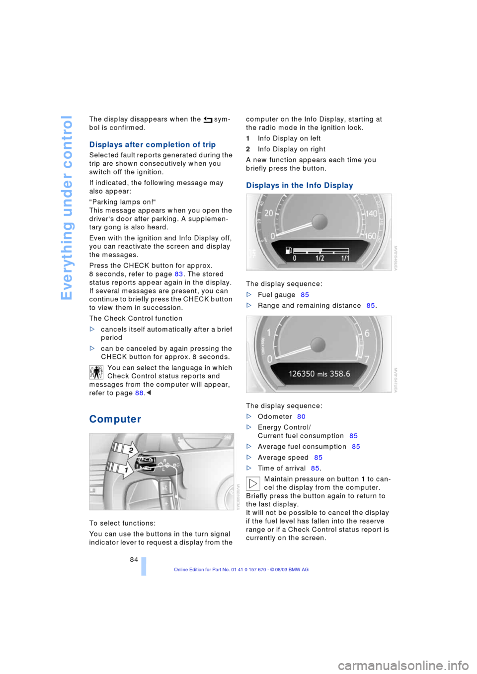
Computer
To select functions:
You can use the buttons in the turn signal
indicator lever to request a display from the computer on the Info Display, starting at
the radio mode in the ignition lock.
1Info Display on left
2Info Display on right
A new function appears each time you
briefly press the button.
Displays in the Info Display
The display sequence:
>Fuel gauge85
>Range and remaining distance85.
The display sequence:
>Odometer80
>Energy Control/
Current fuel consumption85
>Average fuel consumption85
>Average speed85
>Time of arrival85.
Maintain pressure on button 1 to can-
cel the display from the computer.
Briefly press the button again to return to
the last display.
It will not be possible to cancel the display
if the fuel level has fallen into the reserve
range or if a Check Control status report is
currently on the screen.
Page 106 of 232
A congenial climate
104 The air conditioner comes on automatically
when you select the AUTO program.
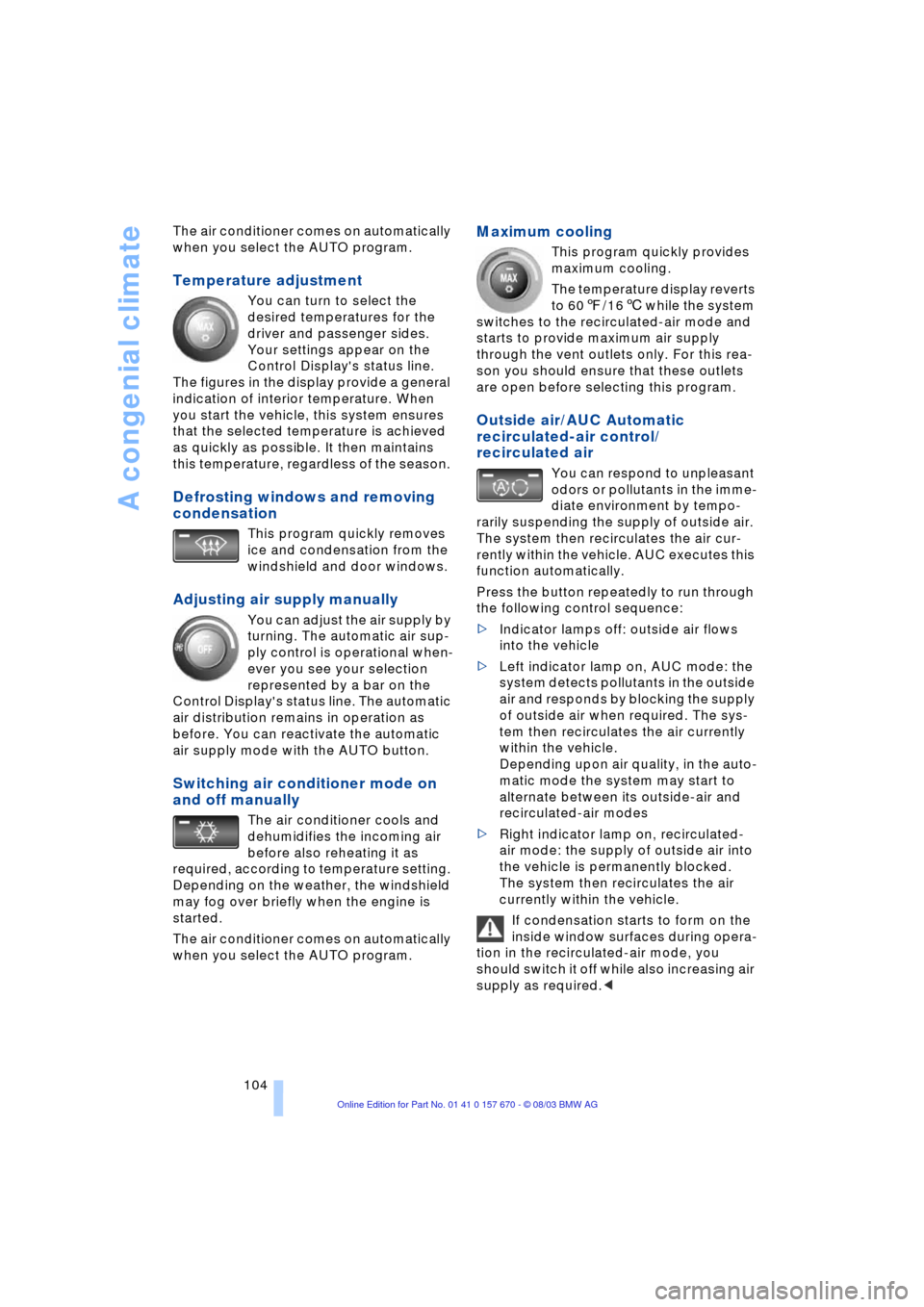
Temperature adjustment
You can turn to select the
desired temperatures for the
driver and passenger sides.
Your settings appear on the
Control Display's status line.
The figures in the display provide a general
indication of interior temperature. When
you start the vehicle, this system ensures
that the selected temperature is achieved
as quickly as possible. It then maintains
this temperature, regardless of the season.
Defrosting windows and removing
condensation
This program quickly removes
ice and condensation from the
windshield and door windows.
Adjusting air supply manually
You can adjust the air supply by
turning. The automatic air sup-
ply control is operational when-
ever you see your selection
represented by a bar on the
Control Display's status line. The automatic
air distribution remains in operation as
before. You can reactivate the automatic
air supply mode with the AUTO button.
Switching air conditioner mode on
and off manually
The air conditioner cools and
dehumidifies the incoming air
before also reheating it as
required, according to temperature setting.
Depending on the weather, the windshield
may fog over briefly when the engine is
started.
The air conditioner comes on automatically
when you select the AUTO program.
Maximum cooling
This program quickly provides
maximum cooling.
The temperature display reverts
to 607/166 while the system
switches to the recirculated-air mode and
starts to provide maximum air supply
through the vent outlets only. For this rea-
son you should ensure that these outlets
are open before selecting this program.
Outside air/AUC Automatic
recirculated-air control/
recirculated air
You can respond to unpleasant
odors or pollutants in the imme-
diate environment by tempo-
rarily suspending the supply of outside air.
The system then recirculates the air cur-
rently within the vehicle. AUC executes this
function automatically.
Press the button repeatedly to run through
the following control sequence:
>Indicator lamps off: outside air flows
into the vehicle
>Left indicator lamp on, AUC mode: the
system detects pollutants in the outside
air and responds by blocking the supply
of outside air when required. The sys-
tem then recirculates the air currently
within the vehicle.
Depending upon air quality, in the auto-
matic mode the system may start to
alternate between its outside-air and
recirculated-air modes
>Right indicator lamp on, recirculated-
air mode: the supply of outside air into
the vehicle is permanently blocked.
The system then recirculates the air
currently within the vehicle.
If condensation starts to form on the
inside window surfaces during opera-
tion in the recirculated-air mode, you
should switch it off while also increasing air
supply as required.<
Page 120 of 232
Practical interior accessories
118
Securing the load
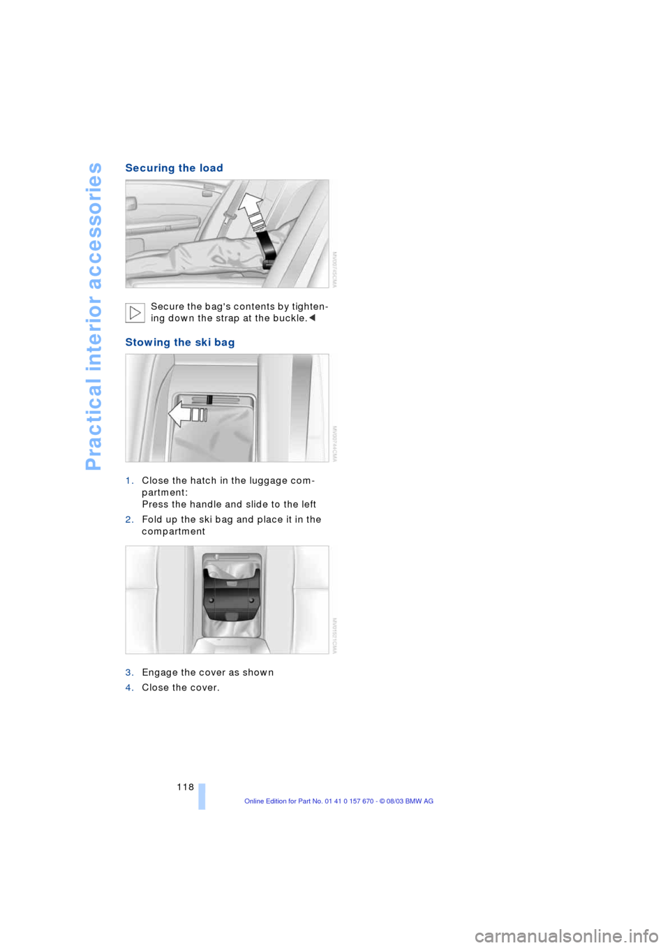
Secure the bag's contents by tighten-
ing down the strap at the buckle.<
Stowing the ski bag
1.Close the hatch in the luggage com-
partment:
Press the handle and slide to the left
2.Fold up the ski bag and place it in the
compartment
3.Engage the cover as shown
4.Close the cover.
Page 127 of 232
Driving tips
125Reference
At a glance
Controls
Communications
Navigation
Entertainment
Mobility
Stowing cargo
>Load heavy cargo as far forward and
as low as possible, placing it directly
behind the bulkhead behind the rear
seats
>Cover sharp edges and corners
>For very heavy cargo when the rear seat
is not occupied, secure each safety belt
in the opposite buckle.
Securing cargo
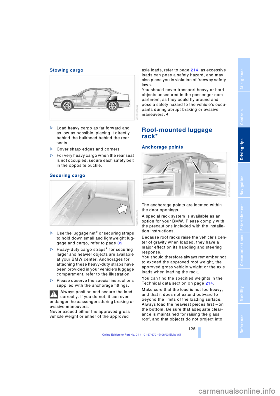
>Use the luggage net* or securing straps
to hold down small and lightweight lug-
gage and cargo, refer to page 39
>Heavy-duty cargo straps
* for securing
larger and heavier objects are available
at your BMW center. Anchorages for
attaching these heavy-duty straps have
been provided in your vehicle's luggage
compartment, refer to the illustration
>Please observe the special instructions
supplied with the anchorage fittings.
Always position and secure the load
correctly. If you do not, it can even
endanger the passengers during braking or
evasive maneuvers.
Never exceed either the approved gross
vehicle weight or either of the approved axle loads, refer to page 214, as excessive
loads can pose a safety hazard, and may
also place you in violation of freeway safety
laws.
You should never transport heavy or hard
objects unsecured in the passenger com-
partment, as they could fly around and
pose a safety hazard to the vehicle's occu-
pants during abrupt braking or evasive
maneuvers .<
Roof-mounted luggage
rack*
Anchorage points
The anchorage points are located within
the door openings.
A special rack system is available as an
option for your BMW. Please comply with
the precautions included with the installa-
tion instructions.
Because roof racks raise the vehicle's cen-
ter of gravity when loaded, they have a
major effect on its handling and steering
response.
You should therefore always remember not
to exceed the approved roof weight, the
approved gross vehicle weight or the axle
loads when loading the rack.
You can find the specified weights in the
Technical data section on page 214.
Make sure that the load is not too heavy,
and that it does not extend outward to
beyond the limits of the loading surface.
Always load the heaviest pieces first Ð on
the bottom. Be sure that adequate clear-
ance is maintained for raising the glass
roof, and that objects do not project into
Page 128 of 232
Things to remember when driving
126 the opening path of the luggage compart-
ment lid.
Secure roof-mounted cargo correctly and
securely to prevent it from shifting or being
lost during the trip.
Drive smoothly. Avoid sudden acceleration
and braking maneuvers. Take corners gen-
tly.
Entry/pass tags
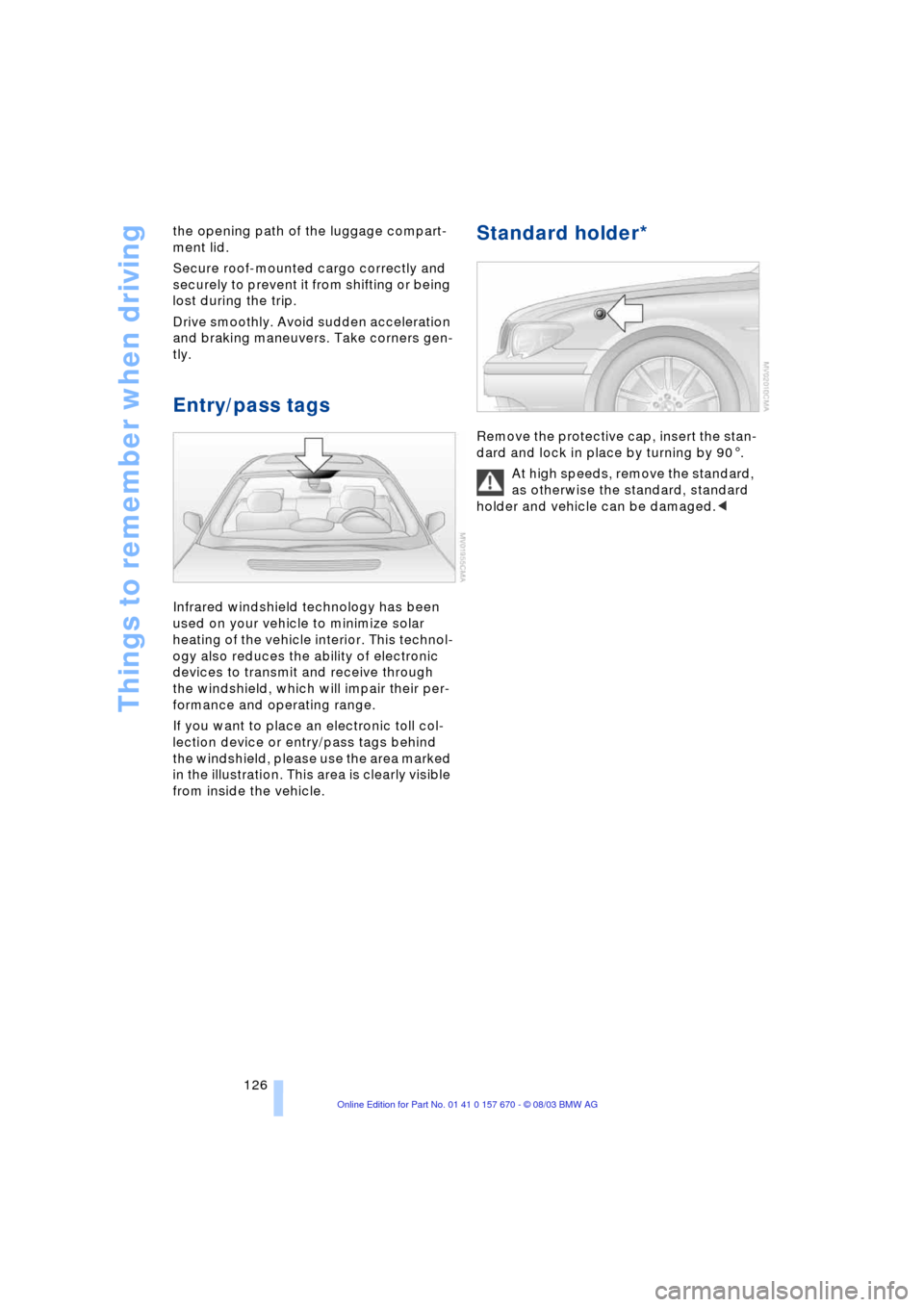
Infrared windshield technology has been
used on your vehicle to minimize solar
heating of the vehicle interior. This technol-
ogy also reduces the ability of electronic
devices to transmit and receive through
the windshield, which will impair their per-
formance and operating range.
If you want to place an electronic toll col-
lection device or entry/pass tags behind
the windshield, please use the area marked
in the illustration. This area is clearly visible
from inside the vehicle.
Standard holder*
Remove the protective cap, insert the stan-
dard and lock in place by turning by 901.
At high speeds, remove the standard,
as otherwise the standard, standard
holder and vehicle can be damaged.<
Page 196 of 232
Under the hood
194
Under the hood
Hood
Releasing
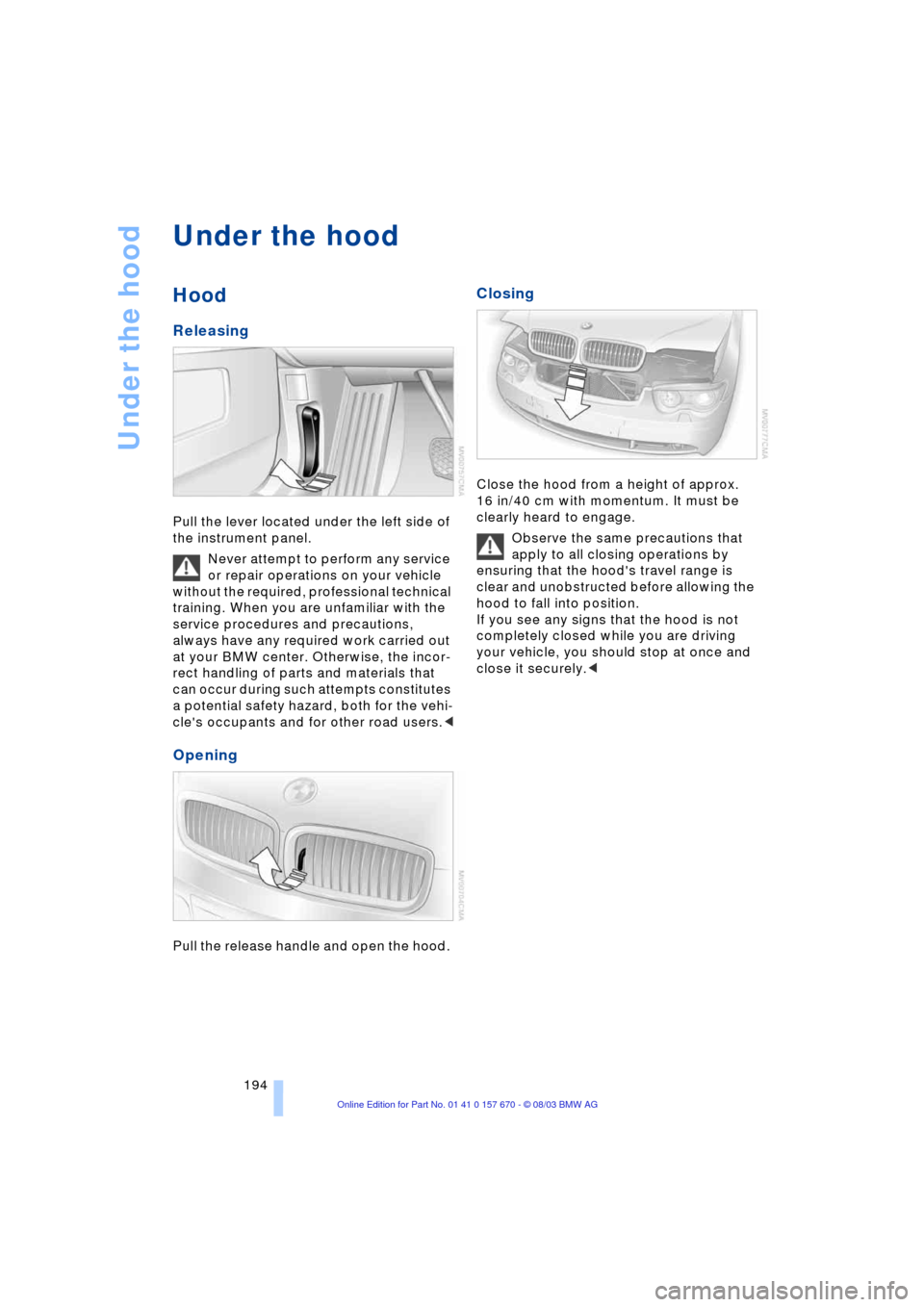
Pull the lever located under the left side of
the instrument panel.
Never attempt to perform any service
or repair operations on your vehicle
without the required, professional technical
training. When you are unfamiliar with the
service procedures and precautions,
always have any required work carried out
at your BMW center. Otherwise, the incor-
rect handling of parts and materials that
can occur during such attempts constitutes
a potential safety hazard, both for the vehi-
cle's occupants and for other road users.<
Opening
Pull the release handle and open the hood.
Closing
Close the hood from a height of approx.
16 in/40 cm with momentum. It must be
clearly heard to engage.
Observe the same precautions that
apply to all closing operations by
ensuring that the hood's travel range is
clear and unobstructed before allowing the
hood to fall into position.
If you see any signs that the hood is not
completely closed while you are driving
your vehicle, you should stop at once and
close it securely.<
Page 205 of 232
Mobility
203Reference
At a glance
Controls
Driving tips
Communications
Navigation
Entertainment
Change the wheel only on a level, firm sur-
face which is not slippery. The vehicle or
the jack could slip to the side if you attempt
to raise the vehicle on a soft or slippery sur-
face such as snow, ice, tiles, etc.
Position the jack on a firm support surface.
Do not use a wooden block or similar
object as a support base for the jack, as
this would prevent it from extending to its
full support height and reduce its load-car-
rying capacity.
To avoid serious or fatal injury: never lie
under the vehicle, and never start the
engine while it is supported by the jack.<
What you will need
To avoid rattling noises, note the positions
of the tools before removing them, then
return them to their initial positions after
completing work.
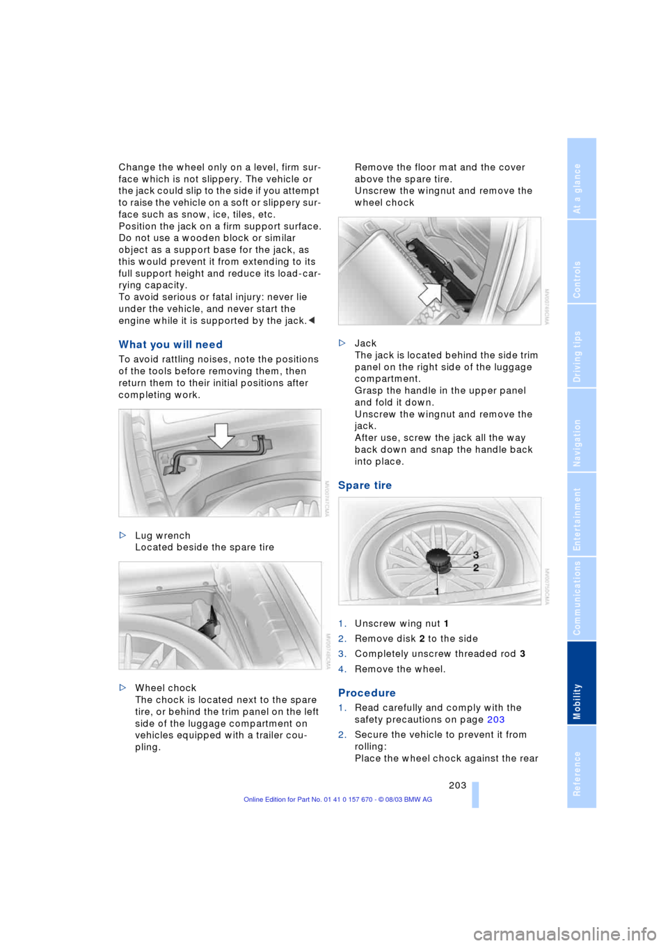
>Lug wrench
Located beside the spare tire
>Wheel chock
The chock is located next to the spare
tire, or behind the trim panel on the left
side of the luggage compartment on
vehicles equipped with a trailer cou-
pling. Remove the floor mat and the cover
above the spare tire.
Unscrew the wingnut and remove the
wheel chock
>Jack
The jack is located behind the side trim
panel on the right side of the luggage
compartment.
Grasp the handle in the upper panel
and fold it down.
Unscrew the wingnut and remove the
jack.
After use, screw the jack all the way
back down and snap the handle back
into place.
Spare tire
1.Unscrew wing nut 1
2.Remove disk 2 to the side
3.Completely unscrew threaded rod 3
4.Remove the wheel.
Procedure
1.Read carefully and comply with the
safety precautions on page 203
2.Secure the vehicle to prevent it from
rolling:
Place the wheel chock against the rear
Page 206 of 232
Replacing components
204 surface of the front tire on the side
opposite the side being raised. If the
vehicle is parked on a downward slope,
place the wheel chock securely in front
of the tire. If the wheel must be changed
on a surface with a more severe slope,
take additional precautions to secure
the vehicle from rolling
3.Loosen the lug bolts 1/2 a turn
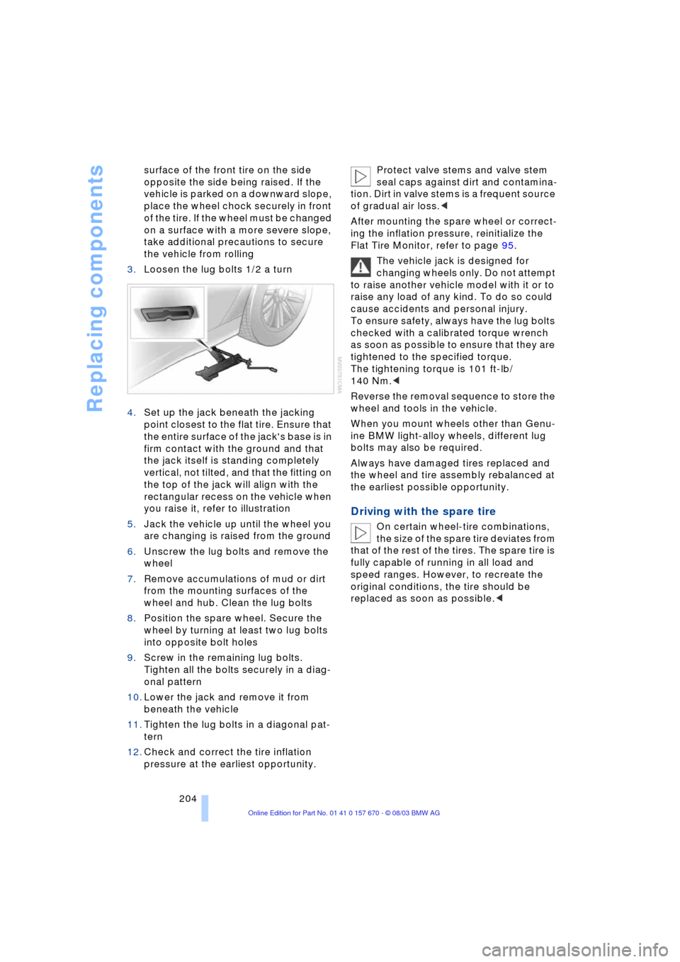
4.Set up the jack beneath the jacking
point closest to the flat tire. Ensure that
the entire surface of the jack's base is in
firm contact with the ground and that
the jack itself is standing completely
vertical, not tilted, and that the fitting on
the top of the jack will align with the
rectangular recess on the vehicle when
you raise it, refer to illustration
5.Jack the vehicle up until the wheel you
are changing is raised from the ground
6.Unscrew the lug bolts and remove the
wheel
7.Remove accumulations of mud or dirt
from the mounting surfaces of the
wheel and hub. Clean the lug bolts
8.Position the spare wheel. Secure the
wheel by turning at least two lug bolts
into opposite bolt holes
9.Screw in the remaining lug bolts.
Tighten all the bolts securely in a diag-
onal pattern
10.Lower the jack and remove it from
beneath the vehicle
11.Tighten the lug bolts in a diagonal pat-
tern
12.Check and correct the tire inflation
pressure at the earliest opportunity. Protect valve stems and valve stem
seal caps against dirt and contamina-
tion. Dirt in valve stems is a frequent source
of gradual air loss.<
After mounting the spare wheel or correct-
ing the inflation pressure, reinitialize the
Flat Tire Monitor, refer to page 95.
The vehicle jack is designed for
changing wheels only. Do not attempt
to raise another vehicle model with it or to
raise any load of any kind. To do so could
cause accidents and personal injury.
To ensure safety, always have the lug bolts
checked with a calibrated torque wrench
as soon as possible to ensure that they are
tightened to the specified torque.
The tightening torque is 101 ft-lb/
140 Nm.<
Reverse the removal sequence to store the
wheel and tools in the vehicle.
When you mount wheels other than Genu-
ine BMW light-alloy wheels, different lug
bolts may also be required.
Always have damaged tires replaced and
the wheel and tire assembly rebalanced at
the earliest possible opportunity.
Driving with the spare tire
On certain wheel-tire combinations,
the size of the spare tire deviates from
that of the rest of the tires. The spare tire is
fully capable of running in all load and
speed ranges. However, to recreate the
original conditions, the tire should be
replaced as soon as possible.<