light BMW M3 1992 E36 Owners Manual
[x] Cancel search | Manufacturer: BMW, Model Year: 1992, Model line: M3, Model: BMW M3 1992 E36Pages: 759
Page 305 of 759
TheE36
convertible
is
an
all-season
vehicle
with
a
high
lev-
e¡offunctionality,
excellent
interior
comfort,
and
acoustic
re-
finement
.
Interior
materials
and
colors,
the
soft
top
and
the
light-alloy
wheelshave
been
carefully
matched
.
Various
versions
of
manual
and
automatic
soft
tops
have
been
used,
with
the
fully
automatic
convertible
roof
being
in-
stalled
beginning
in
the
1997
model
year
.
A
hard-top
in
body
color
with
heated
rear
window
is
avail-
ableas
an
option
for
the
cold
season
.
BODY-GENERAL
400-
3
Coupe
Models
The
convertible
body
structure
includes
many
passive
safe-
ty
refinements
over
its
fixed-top
counterparts
.
Some
of
the
en-
TheE36
coupe
is
similar
to
the4-door
sedan,
but
has
a
hancements
include
:
more
stretched
and
sleeker
appearance
.
Thus,
with
the
same
wheelbase
and
identicallength,
it
looks
different
but
still
famil-
"
More
rígíd
underbody
.
iar
.
"
Transverse
seat
members
.
"
Reinforced
windshield
frame
with
bonded
windshield,
The
2-door
variant
differs
from
the
4-door
sedan
by
a
3
.12
and
tubular
door
reinforcements
.
inch
(8
cm)
longer
front
end,
a
flatter
hood
line
with
air
slits,
"
Rollover
protection
system,
which
is
tripped
into
position
and
a
roof
almost
1
.2
inches
(3
cm)
shorter
.
Additional
differ-
in
a
fraction
of
second
.
This
is
available
as
optional
ences
include
wider
doors
with
frameless
Windows,
glass-
equipment
(standard
on
the
1998
328iC)
and
may
be
fit-
covered
door-posts
(B-pillars)
and
a
shorter
and
lower
lug-
ted
to
earlier
convertible
models
.
With
this
feature,
two
gage
compartment
lid
.
bars
fully
independent
of
each
other
come
up
behind
each
rear-seat
backrest
when
the
vehicle
is
in
danger
of
Convertible
Models
turning
over
.
A
convertible
body
normally
flexes
and
vibrates,
transfer-
ring
oscillations
to
the
luggage
compartment
.
In
the
E36
con-
vertible,
BMW
utilizes
a
special
battery
in
the
luggage
compartment,
in
conjunction
with
a
unique
battery
tray,
asa
vibration
dampening
system
to
counteract
thisoscillation
.
CAUTION
-
The
E36
convertible
requires
a
specialbattery
which
is
designed
for
constant
vibration
.
Information
for
the
convertible
top
and
its
related
mecha-
nisms
can
be
found
541
Convertible
Top
.
BODYASSEMBLY
Page 306 of 759
400-
4
BODY-GENERAL
INTERIOR
EQUIPMENT
E36
interiors
have
a
unique
character,
with
a
combínation
of
sporty
features
and
innovative
design
.
Al¡
body
versions
were
made
in
a
wide
choice
of
interior
and
exterior
colors
.
New
colors
with
matching
leather
and/or
fabric
upholstery
were
in-
troduced
for
each
model
year,
including
light-alloy
wheels
in
new
designs
.
Driving
comfort
is
enhanced
by
power
steering,
tilt
steering
wheel
(optional),
height-adjustable
front
seats,
and
electrical-
ly
adjustable
and
heated
rear-view
mirrors
.
Inside
thecar
there
are
reading
lights
at
four
seating
positions
.
Seats
and
Seat
Belts
NOTE-
Theseat
base
usedon
cars
with
pyrotechnic
seatbelt
Anatom¡cal
ly-correct
seats
are
constructed
from
polyure-
tensioners
is
not
interchangeable
with
the
earlier
seat
thane
foam
containing
areas
or
"zones"
of
different
firmness
.
base
.
The
seat
bases
have
steel
springs
for
added
support
and
strength
.
The
power
seats
are
provided
with
conveniently
lo-
Instruments
and
Controls
cated
switches
along
the
outside
edge
of
the
seat
.
Heated
seats
are
an
option
in
all
models
.
See
520
Seats
for
more
de-
Everything
in
the
interior
passenger
compartment
essential
tails
.
to
the
driver
is
logically
grouped
and
easy
to
reach
.
Al¡
instru-
ments
and
controls
havebeen
arranged
ergonomically
and
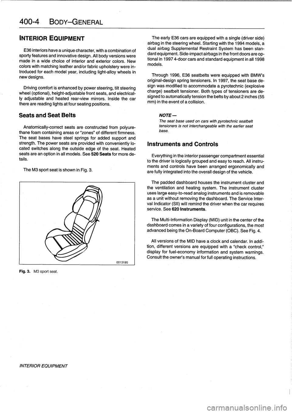
The
M3
sport
seat
is
shown
in
Fig
.
3
.
are
fully
integrated
into
the
overall
design
of
the
vehicle
.
Fig
.
3
.
M3
sport
seat
.
INTERIOR
EQUIPMENT
0013195
The
early
E36
cars
areequipped
with
a
single
(driver
side)
airbag
in
the
steering
wheel
.
Startingwith
the
1994
models,
a
dual
airbag
Supplemental
Restraint
System
has
been
stan-
dard
equipment
.
Side-impact
airbags
in
the
front
doors
are
op-
tional
in
1997
4-door
cars
and
standard
equipment
in
all
1998
models
.
Through
1996,
E36
seatbelts
were
equipped
with
BMW's
original-designspring
tensioners
.
In
1997,
the
seat
base
de-
sign
was
modified
to
accommodate
a
pyrotechnic
(explosive
charge)
seatbelt
tensioner
.
Both
types
of
tensioners
arede-
signed
to
automatically
tension
the
belts
by
about2
inches(55
mm)
in
the
event
of
a
collision
.
The
padded
dashboard
houses
the
instrument
cluster
and
the
ventilation
and
heating
system
.
The
instrument
cluster
uses
large
easy-to-read
analog
instruments
and
is
removable
as
a
unit
without
removing
the
dashboard
.
The
Service
Inter-
val
Indicator
(SII)
will
remind
the
driver
when
thecar
requires
service
.
See
620
Instruments
.
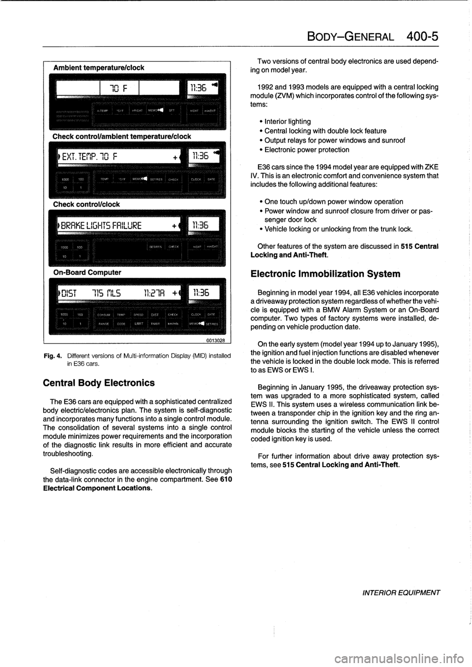
The
Multi-Information
Display
(MID)
unit
in
thecenter
of
the
dashboard
comes
in
a
variety
of
four
configurations,
the
most
advanced
being
the
On-Board
Computer
(OBC)
.
See
Fig
.
4
.
Al¡
versions
of
the
MID
have
a
clock
and
calendar
.
In
addi-
tion,
different
versions
areequipped
with
a
"check
control,"
display
for
fuel-economy
information
and
system
warnings
.
Consult
the
owner's
manual
for
fui¡
operating
instructions
.
Page 307 of 759
Ambient
temperaturelclock
MÍM
Aa
.Mi}rm
-Mil"
IMua~naa~u~itacar
"
za
.~
Central
Body
Electronics
0013028
Fig
.
4
.
Different
versionsof
Multi-information
Display(MID)
installed
in
E36
cars
.
The
E36
cars
are
equipped
with
a
sophisticated
centralized
body
electric/electronics
plan
.
The
system
is
self-diagnostic
and
incorporates
many
functions
into
a
single
control
module
.
The
consolidation
of
several
systems
into
a
single
control
module
minimizes
power
requirements
and
the
incorporation
of
the
diagnostic
link
results
in
more
efficient
and
accurate
troubleshooting
.
Self-diagnostic
codes
are
accessible
electronically
through
the
data-link
connector
in
the
engine
compartment
.
See610
Electrical
Component
Locations
.
BODY-GENERAL
400-
5
Two
versions
of
central
body
electronics
are
used
depend-
ing
on
model
year
.
1992
and
1993
models
are
equipped
with
a
central
locking
module
(ZVM)
which
incorporates
control
of
the
following
sys-
tems
:
"Interiorlighting
"
Central
locking
with
double
lock
feature
"
Output
relays
for
powerwindows
and
sunroof
"
Electronic
power
protection
E36
cars
since
the
1994
model
year
are
equipped
with
ZKE
IV
.
This
is
an
electronic
comfort
and
convenience
system
that
includes
the
following
additional
features
:
"
One
touch
up/down
power
window
operation
"
Power
window
and
sunroof
closure
from
driver
or
pas-
sengerdoor
lock
"
Vehicle
locking
or
unlocking
from
the
trunk
lock
.
Other
features
of
the
system
are
discussed
in
515
Central
Locking
and
Anti-Theft
.
Electronic
Immobilization
System
Beginning
in
model
year
1994,
all
E36
vehicles
incorporate
adriveaway
protection
system
regardless
of
whether
the
vehi-
cle
is
equipped
with
a
BMW
Alarm
System
or
an
On-Board
computer
.
Two
types
of
factory
systems
were
installed,
de-
pending
on
vehicle
production
date
.
On
the
early
system
(model
year
1994
up
to
January
1995),
the
ignition
and
fuel
injection
functions
are
disabled
whenever
the
vehicle
is
locked
in
the
double
lock
mode
.
This
is
referred
lo
as
EWS
or
EWS
I
.
Beginning
in
January
1995,
the
driveaway
protection
sys-
tem
was
upgraded
to
a
more
sophisticated
system,
called
EWS
II
.
This
system
uses
a
wireless
communication
link
be-
tween
a
transponder
chip
in
the
ignition
keyand
the
ring
an-
tenna
surrounding
the
ignition
switch
.
The
EWS
II
control
module
blocksthe
starting
of
the
vehicle
unlessthe
correct
coded
ignition
key
is
used
.
For
further
information
about
drive
away
protection
sys-
tems,
see
515
Central
Locking
and
Anti-Theft
.
INTERIOR
EQUIPMENT
Page 309 of 759
GENERAL
This
repair
group
covers
replacement
of
the
front
fenders
and
removal
and
installation
of
the
engine
hood
.
NOTE-
The
body
is
painted
at
the
factoryafter
assembly
.
Re-
alignment
of
body
panels
may
expose
unpainted
metal
.
Paint
all
exposed
metal
once
the
work
fs
complete
.
FRONT
FENDERS
Front
fender,
removing
and
installing
1
.
Raise
hood
.
Raise
and
safely
support
front
of
vehicle
.
WARNING
-
"
When
raising
thecar
using
a
floor
jack
or
a
hy-
draulic
lift,
carefully
position
the
jack
pad
to
pre-
vent
damaging
thecar
body
.
A
suitable
liner
(wood,
rubber,
etc
.)
should
be
placed
between
the
jack
and
the
car
to
prevent
body
damage
.
"
Watch
the
jack
closely
.
Make
sure
it
stays
stable
and
does
not
shift
or
tilt
.
As
the
car
is
raised,
the
car
may
roll
slightly
and
the
jack
may
shift
.
2
.
Remove
front
wheel
.
Remove
inner
plastic
liner
from
wheel
well
.
3
.
Remove
front
bumper
.
See510
Exterior
Trim,
Bumpers
.
4
.
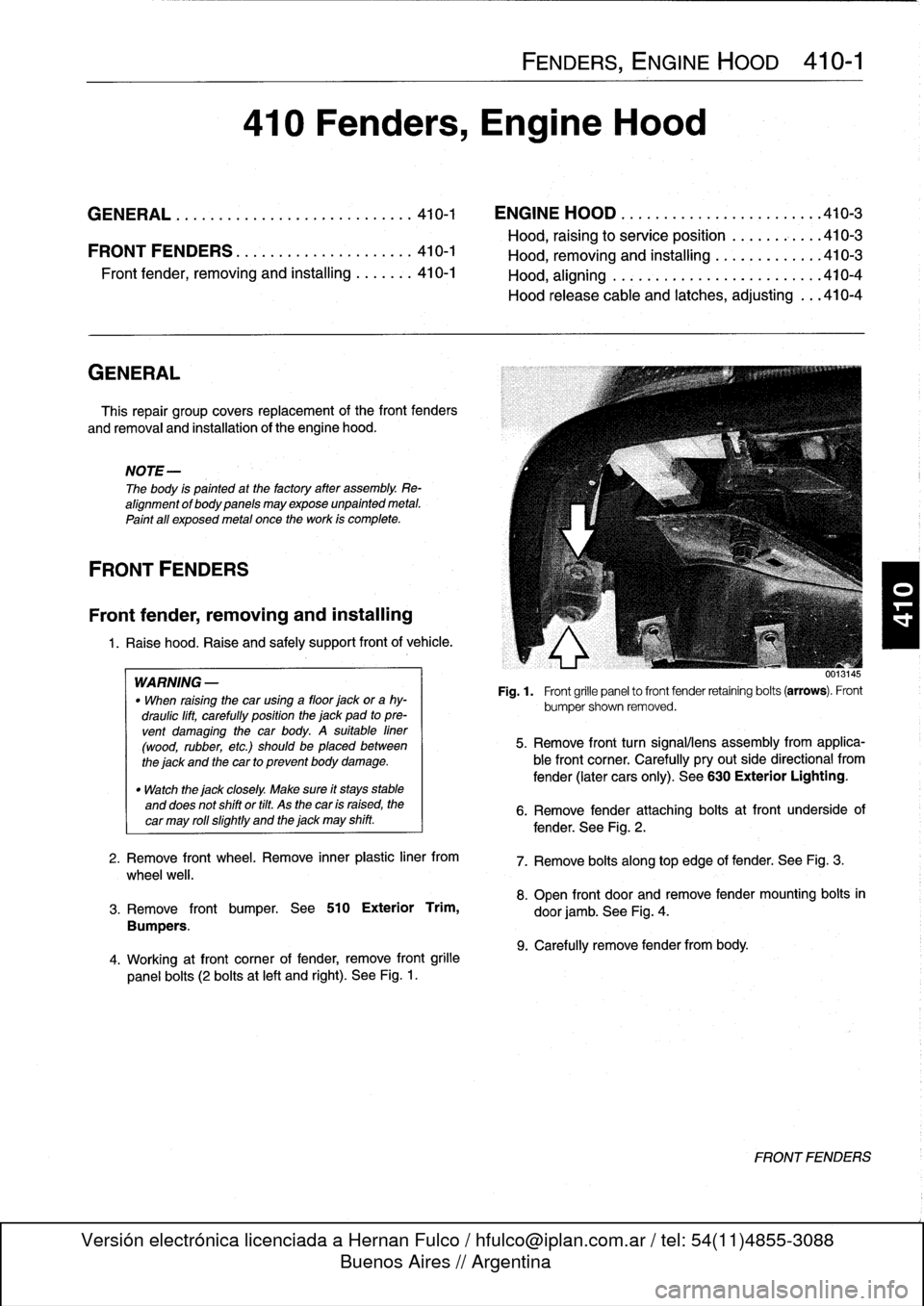
Working
atfront
corner
of
fender,
remove
front
grille
panel
bolts
(2
bolts
at
left
and
right)
.
See
Fig
.
1
.
FENDERS,
ENGINE
HOOD
410-1
410
Fenders,
Engine
Hood
GENERAL
...............
.
.
.
.
.
.
.
.
.
.
.
..
410-1
ENGINE
HOOD
.
.
.
.
.
.
.
.
.
.
.
.
.
.
.
.
.
.
.
...
.
.410-3
Hood,
raising
to
service
position
.
.
.
.
.
.
.
.
...
410-3
FRONTFENDERS
........
.
.
.
.
.
.
.
.
.
.
.
.
.410-1
Hood,
removin
and
installin
410-3
Front
Pender,
removing
and
installing
.
.
.
....
410-1
Hood,
aligning
...
.
.
.
.
.
.
.
.....
.
.
.
.
.
.
.
...
410-4
Hood
release
cable
and
latches,
adjusting
...
410-4
001
.145
Fig
.
1
.
Front
grille
panel
to
front
fender
retaining
bolts
(arrows)
.
Front
bumpershown
removed
.
5
.
Remove
front
turn
signalliens
assembly
from
applica-
ble
front
corner
.
Carefully
pryout
side
directional
from
fender
(later
cars
only)
.
See
630
Exterior
Lighting
.
6
.
Remove
fender
attaching
bolts
atfront
underside
of
fender
.
See
Fig
.
2
.
7
.
Remove
bolts
along
top
edge
of
fender
:
See
Fig
.
3
.
8
.
Open
front
door
and
remove
fender
mounting
bolts
in
door
jamb
.
See
Fig
.
4
.
9
.
Carefully
remove
fender
from
body
.
FRONTFENDERS
Page 316 of 759
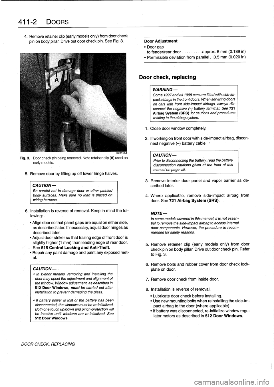
411-2
DOORS
4
.
Remove
retainer
clip
(early
models
only)
from
doorcheck
pin
onbody
pillar
.
Drive
out
door
check
pin
.
See
Fig
.
3
.
Door
Adjustment
"
Door
gap
to
fender/rear
door
.........
approx
.
5
mm
(0
.189
in)
"
Permíssible
deviation
from
parallel
.
.0
.5
mm
(0
.020
in)
0011651
Fig
.
3
.
Door
check
pin
being
removed
.
Note
retainer
clip
(A)
usedon
early
models
.
5
.
Remove
doorby
lifting
up
off
lowerhinge
halves
.
CAUTION-
Be
careful
not
to
damage
door
or
other
painted
body
surfaces
.
Make
sure
no
load
is
placedon
wiring
harness
.
6
.
Installation
is
reverse
of
removal
.
Keep
in
mind
the
fol-
lowing
:
"
Align
doorso
that
panel
gaps
are
equal
on
either
side,
as
described
later
.
If
necessary,
adjust
door
hinges
as
described
later
.
"
Adjust
door
striker
so
that
trailing
edge
of
front
door
is
slightly
higher
(1
mm)
than
leading
edge
of
rear
door
.
See
515
Central
Locking
and
Anti-Theft
.
"
Repair
any
paint
damage
and
paínt
any
exposed
met-
al
.
CAUTION-
.
"In
2-door
models,
removing
and
installing
the
door
may
upset
the
adjustment
and
alignment
of
the
window
.
Window
adjustment,
as
described
in
512DoorWindows,
must
be
carried
out
ater
installation
to
prevent
damaging
the
glass
.
"
If
battery
power
is
lost
or
the
battery
has
been
disconnected,
the
windows
must
be
re-initialized
.
Both
one
touch
upldown
and
pinch-protection
will
be
inactive
until
windows
are
re-initialized
.
See
512
Door
Windows
.
DOOR
CHECK,
REPLACING
Door
check,replacing
WARNING
-
Some
1997
and
all
1998
cars
are
fitted
with
side-im-
pact
airbags
in
the
front
doors
.
When
servicing
doors
on
cars
with
front
side-impact
airbags,
always
dis-
connect
the
negative
(-)
battery
terminal
.
See
721
Al
rbag
System
(SRS)
for
cautions
and
procedures
relating
to
the
airbag
system
.
1
.
Closedoor
window
completely
.
2
.
If
working
on
front
door
with
side-impact
airbag,
discon-
nect
negative
(-)
battery
cable
.,
CAUTION-
Prior
to
disconnectiog
the
battery,
read
the
battery
disconnection
cautions
gíven
at
the
front
of
this
manual
on
page
viii
.
3
.
Remove
interior
door
panel
and
vapor
barrier
as
de-
scribed
later
.
4
.
Where
applicable,
remove
side-impact
airbag
from
door
.
See
721
Airbag
System
(SRS)
.
NOTE-
In
some
models
covered
inthis
manual,
ít
is
not
essen-
tial
to
remove
the
side-ímpact
airbag
to
access
internal
door
components
.
However,
the
procedure
is
recom-
mended
for
safety
reasons
.
5
.
Remove
retainer
clip
(early
models
only)
from
door
check
pin
on
body
pillar
.
Drive
out
door
check
pin
.
Refer
to
Fig
.
3
.
6
.
Remove
bolts
and
rubber
cover
fromdoor
check
lock-
plate
ondoor
.
7
.
Remove
door
check
from
inside
door
.
8
.
Installation
is
reverse
of
removal
.
"
Lubricate
door
check
before
installing
.
"
Use
new
mounting
bolts
when
reinstalling
the
side-im-
pact
airbag
to
thedoor(where
applicable)
.
"
If
battery
was
disconnected,
re-initialize
window
regu-
lator
motors
as
described
in
512
Door
Windows
.
Page 325 of 759
BUMPERS
Front
bumper,
removing
and
installing
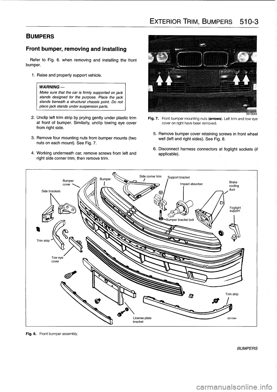
Refer
to
Fig
.
6
.
when
removing
and
installing
the
front
bumper
.
1
.
Raise
and
properly
support
vehicle
.
WARNING
-
Make
sure
that
the
car
is
firmly
supportedonjack
stands
designed
for
the
purpose
.
Place
the
jackstands
beneath
a
structural
chassis
point
.
Do
not
place
jack
stands
undersuspension
parts
.
2
.
Unclip
left
trim
strip
by
prying
gently
under
plastic
trim
at
front
of
bumper
.
Similarly,
unclip
towing
eyecoverfrom
right
side
.
5
.
Remove
bumper
cover
retaining
screws
in
front
wheel
3
.
Remove
four
mounting
nuts
from
bumper
mounts
(two
well
(left
and
right
sides)
.
See
Fig
.
8
.
nuts
on
eachmount)
.
See
Fig
.
7
.
4
.
Working
underneath
car,
removescrews
from
left
and
right
side
corner
trim,
then
remove
trim
.
Side
brackets
Bumper
cover
Fig
.
6
.
Front
bumper
assembly
.
EXTERIOR
TRIM,
BUMPERS
510-3
Fig
.
7
.
Front
bumper
mounting
nuts
(arrows)
.
Lefttrim
andtow
eye
cover
on
right
have
been
removed
.
6
.
Disconnect
harness
connectors
at
foglight
sockets
(if
applicable)
.
Side
corner
trim
Support
bracket
Impact
absorber
o
O
Foglight
support
LBumner
bracket
bolt
License
plata
0011944
bracket
BUMPERS
Page 329 of 759
BMW
emblem,
removing
and
installing
The
procedure
given
below
applies
to
both
front
and
rear
emblems
.
1
.
Wrap
and
of
a
screwdriver
with
tape
.
CAUTION-
Protect
hood
paint
by
coveringarea
aroundem-
blem
with
tape
.
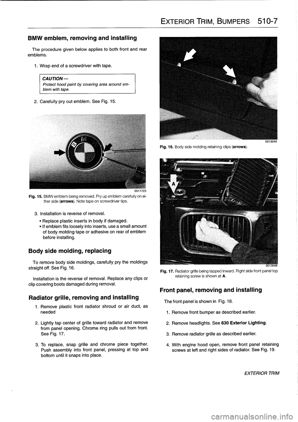
2
.
Carefully
pryout
emblem
.
See
Fig
.
15
.
UVI1'¿.
Fig
.
15
.
BMW
emblem
being
removed
.
Pry
up
emblem
carefully
on
ei-
ther
side
(arrows)
.
Note
tape
on
screwdriver
tips
.
3
.
Installation
is
reverse
of
removal
.
"
Replace
plastic
inserts
in
body
if
damaged
.
"
If
emblem
fits
loosely
intoinserts,
use
a
small
amount
of
bodymoldingtape
or
adhesiva
on
rear
of
emblem
before
installing
.
Body
side
molding,
replacing
To
remove
body
side
moldings,
carefully
pry
the
moldings
straight
off
.
See
Fig
.
16
.
Installation
is
the
reverse
of
removal
.
Replace
any
clips
or
clip
covering
boots
damaged
during
removal
.
Radiator
grille,
removing
and
installing
1
.
Remove
plastic
front
radiator
shroud
or
air
duct,
as
needed
2
.
Lightly
tap
center
of
grilla
toward
radiator
andremove
from
panel
opening
.
Chrome
ring
pulís
out
from
front
.
See
Fig
.
17
.
3
.
To
replace,
snap
grille
andchrome
piece
together
.
Push
assembly
into
front
panel,
pressing
at
top
and
bottom
until
it
snaps
into
place
.
EXTERIOR
TRIM,
BUMPERS
510-7
Fig
.
16
.
Body
sida
molding
retainingclips
(arrows)
.
-
0013048
Fig
.
17
.
Radiator
grille
being
tapped
inward
.
Right
side
front
panel
top
retaining
screw
is
shown
at
A
.
Front
panel,
removing
and
installing
The
front
panel
is
shown
in
Fig
.
18
.
1
.
Remove
front
bumper
as
described
earlier
.
2
.
Remove
headlights
.
See
630
Exterior
Lighting
.
3
.
Remove
radiator
grille
as
described
earlier
.
4
.
With
engine
hood
open,
remove
front
panel
retaining
screws
at
left
and
right
sides
of
radiator
.
See
Fig
.
19
.
EXTERIOR
TRIM
Page 333 of 759
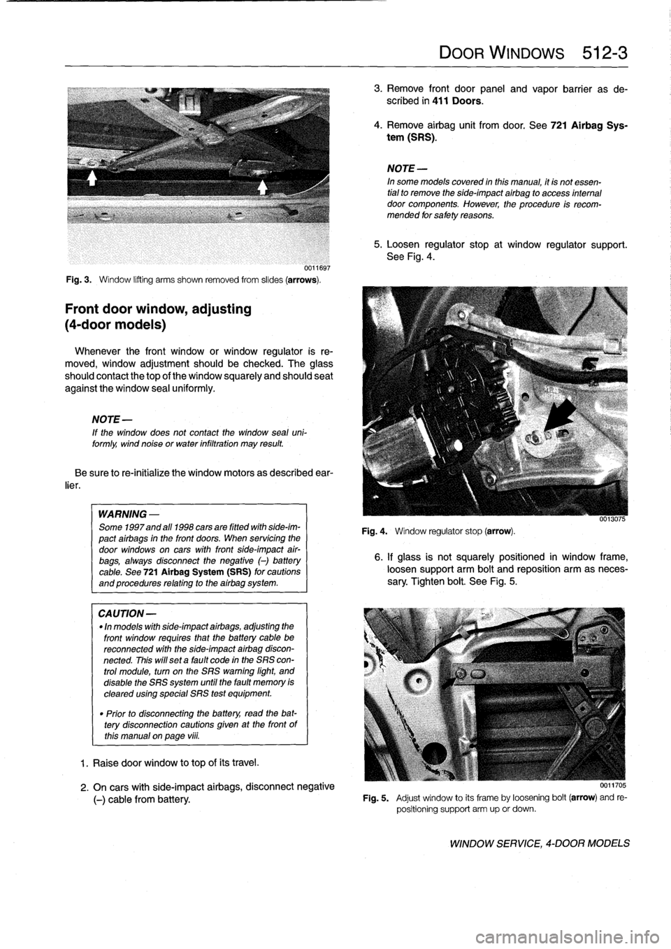
0011697
Fig
.
3
.
Window
lifting
arms
shown
removed
from
slides
(arrows)
.
Front
door
window,
adjusting
(4-door
models)
Whenever
the
front
window
or
window
regulator
is
re-
moved,
window
adjustment
should
be
checked
.
The
glass
should
contact
the
top
of
the
window
squarely
and
should
seat
against
the
window
sea¡
uniformly
.
NOTE
-
If
the
window
does
not
contact
the
window
seal
uni-formly,
wind
noise
or
water
infiltration
may
result
Be
sure
to
re-initialize
the
window
motors
as
described
ear-
lier
.
WARNING
-
Some
1997and
all
1998
cars
are
fitted
wíthside-im-
pact
airbags
in
the
front
doors
.
When
servicing
the
door
windows
on
cars
with
front
side-impact
air-
bags,
always
disconnect
the
negative
()
battery
cable
.
See
721Airbag
System
(SRS)
for
cautions
and
procedures
relating
to
the
airbag
system
.
CA
UTION-
"
In
models
with
side-impact
airbags,
adjusting
the
front
window
requires
that
the
battery
cable
bereconnected
with
the
side-impact
airbag
discon-
nected
.
This
will
set
a
fault
code
in
the
SRS
con-
trol
module,
turn
on
the
SRS
warning
light,
and
disable
the
SRS
system
until
the
fault
memory
is
cleared
using
special
SRS
test
equipment
.
"
Prior
to
disconnectiog
the
battery,
read
the
bat-tery
disconnection
cautions
given
at
the
front
of
this
manual
on
page
viii
.
1
.
Raise
door
window
to
top
of
its
travel
.
DOOR
WINDOWS
512-
3
3
.
Remove
front
door
panel
and
vapor
barrier
as
de-
scribed
in
411
Doors
.
4
.
Remove
airbag
unit
from
door
.
See
721Airbag
Sys-
tem
(SRS)
.
NOTE-
In
some
models
covered
inthis
manual,
it
is
not
essen-
tial
to
remove
the
side-impact
airbag
to
access
interna¡
door
components
.
However,
the
procedure
is
recom-
mended
for
safety
reasons
.
5
.
Loosen
regulator
stop
at
window
regulator
support
.
See
Fig
.
4
.
Fig
.
4
.
Wíndow
regulator
stop
(arrow)
.
0013075
6
.
If
glass
is
not
squarely
positioned
in
window
frame,
loosen
support
arm
bolt
and
reposition
arm
as
neces-
sary
.
Tighten
bolt
.
See
Fig
.
5
.
2
.
On
cars
with
side-impact
airbags,
disconnect
negative
(-)
cable
from
battery
.
Fig
.
5
.
Adjust
window
to
its
frameby
loosening
bolt
(arrow)
and
re-
positioning
support
arm
up
or
down
.
WINDOW
SERVICE,
4-DOOR
MODELS
Page 335 of 759
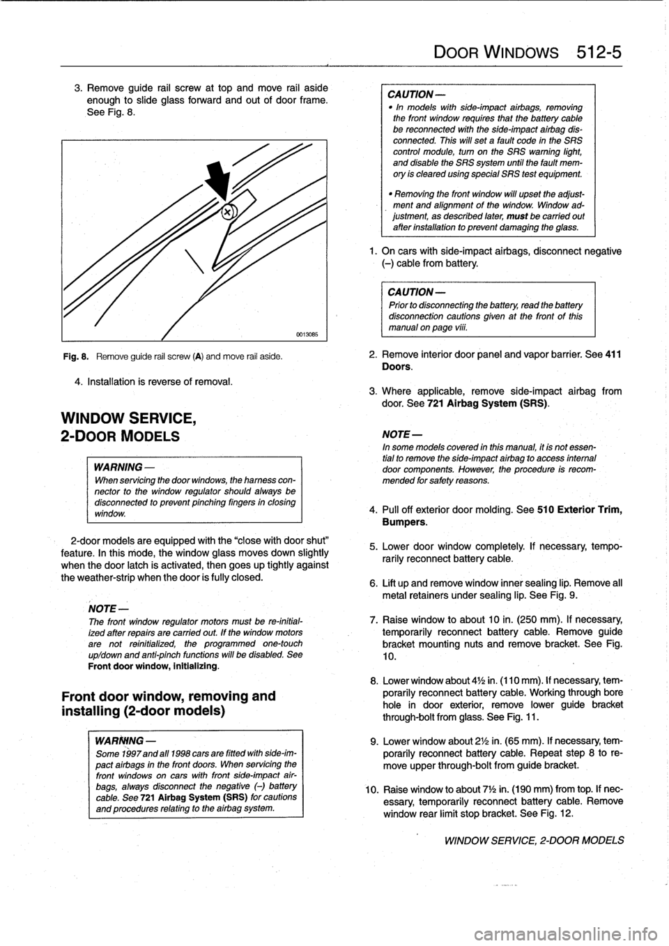
3
.
Remove
guide
rail
screw
at
top
and
move
rail
aside
enough
to
slide
glass
forward
and
out
of
door
frame
.
See
Fig
.
8
.
4
.
Installation
is
reverse
of
removal
.
WINDOW
SERVICE,
2-DOOR
MODELS
WARNING
-
When
servicing
the
door
windows,
the
hamess
con-
nector
to
the
window
regulator
shouldalwaysbe
disconnectod
to
prevent
pinching
fingers
in
closing
window
.
2-door
models
are
equipped
with
the
"close
with
door
shut"
feature
.
In
this
rriode,
the
window
glass
moves
down
slightly
when
the
door
latch
is
activated,
then
goes
up
tightly
against
the
weather-strip
when
the
door
is
fully
closed
.
Front
door
window,
removing
and
installing
(2-door
models)
WARIWNG
-
Some
1997and
a111998
cars
are
fitted
with
side-im-
pact
airbags
in
the
front
doors
.
When
servicing
the
front
windows
on
cars
with
front
side-impact
air-
bags,
always
disconnect
the
negative
(-)
battery
cable
.
See
721
Airbag
System(SRS)
for
cautions
and
procedures
relating
to
the
airbag
system
.
DOOR
WINDOWs
512-
5
CAUTION-
"In
models
with
side-impact
airbags,
removing
the
front
window
requires
fhat
the
battery
cable
be
reconnected
with
the
side-impact
airbag
dis-
connected
.
This
will
set
a
fault
code
in
the
SRS
control
module,
turn
on
the
SRS
warning
light,
and
disable
the
SRS
system
until
the
fault
mem-
ory
is
cleared
using
special
SRS
test
equipment
.
"
Removing
the
front
window
will
upset
the
adjust-
ment
and
alignment
of
the
window
.
Window
ad-justment,
as
described
later,
must
be
carried
out
after
installation
to
prevent
damaging
the
glass
.
1.
On
carswith
side-impact
airbags,
disconnect
negative
(-)
cable
from
battery
.
CAUTION-
Prior
to
disconnectiog
the
battery,
read
the
battery
disconnection
cautions
given
at
the
front
of
this
manual
on
page
viii
.
Fig
.
8
.
Remove
guide
rail
screw
(A)
and
move
rail
aside
.
2
.
Remove
interior
door
panel
and
vapor
barrier
.
See
411
Doors
.
3
.
Where
applicable,
remove
side-impact
airbag
from
door
.
See
721
Airbag
System
(SRS)
.
NOTE-
In
some
models
covered
in
this
manual,
it
is
notessen-
tial
to
remove
the
side-impact
airbag
lo
access
intemal
door
components
.
However,
the
procedure
is
recom-
mended
for
safety
reasons
.
4
.
Pull
off
exterior
doormolding
.
See
510
Exterior
Trim,
Bumpers
.
5
.
Lower
door
window
completely
If
necessary,
tempo-
rarily
reconnect
battery
cable
.
6
.
Lift
up
and
remove
window
innersealing
lip
.
Remove
all
metal
retainers
under
sealing
lip
.
See
Fig
.
9
.
NOTE
-
The
front
window
regulator
motors
must
be
re-initial-
7
.
Raise
window
to
about10
in
.
(250
mm)
.
If
necessary,
ized
after
repairs
are
carried
out
.
If
the
window
motors
temporarily
reconnect
battery
cable
.
Remove
guide
arenot
reinitialized,
the
programmed
one-touch
bracket
mounting
nuts
and
remove
bracket
.
See
Fig
.
up/down
and
anti-pinch
functions
will
be
disabled
.
See
10,
Front
doorwindow,
initializing
.
8
.
Lower
window
about
4'/2
in
.
(110mm)
.
If
necessary,
tem-
porarily
reconnect
batterycable
.
Working
through
bore
hole
in
door
exterior,
remove
lower
guide
bracket
through-bolt
from
glass
.
See
Fig
.
11
.
9
.
Lower
window
about
2'/2
in
.
(65
mm)
.
If
necessary,
tem-
porarily
reconnect
battery
cable
.
Repeat
step
8
to
re-
move
upper
through-bolt
from
guide
bracket
.
10
.
Raise
window
to
about
7
1
/2in
.
(190
mm)
from
top
.
If
nec-
essary,
temporarily
reconnect
batterycable
.
Remove
window
rear
limit
stop
bracket
.
See
Fig
.
12
.
WINDOW
SERVICE,
2-DOOR
MODELS
Page 337 of 759
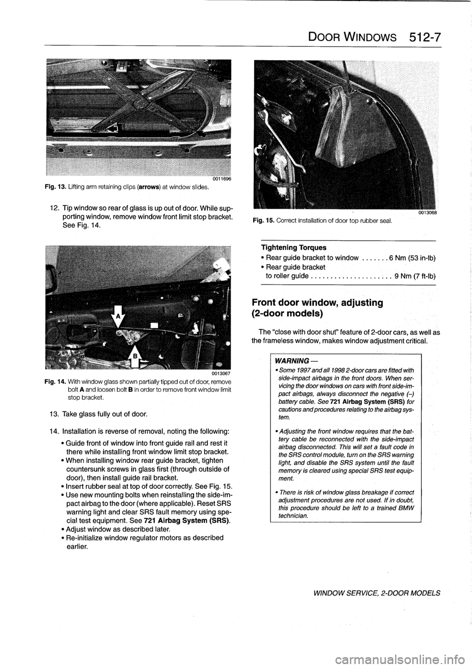
Fig
.
13
.
Lifting
arm
retaining
clips
(arrows)
at
window
slides
.
12
.
Tip
window
so
rear
ofglass
is
up
out
of
door
.
While
sup-
porting
window,
remove
window
front
limit
stopbracket
.
See
Fig
.
14
.
0013067
Fig
.
14
.
With
window
glass
shown
partially
tipped
out
of
door,
remove
bolt
A
and
loosen
bolt
B
in
order
to
remove
front
window
limit
stop
bracket
.
13
.
Take
glass
fully
out
of
door
.
14
.
Installation
is
reverse
of
removal,notingthe
following
:
"
Guide
front
of
window
into
front
guide
rail
and
rest
it
therewhile
installing
front
window
limit
stop
bracket
.
"
When
installing
window
rear
guide
bracket,
tighten
countersunk
screws
in
glass
first
(throughoutside
of
door),
then
install
guide
rail
bracket
.
"
Insert
rubber
sea¡
at
top
of
door
correctly
See
Fig
.
15
.
"
Use
new
mounting
bolts
when
reinstalling
the
side-im-
pactairbag
to
the
door
(where
applicable)
.
Reset
SRS
warning
light
and
clear
SRS
fault
memory
using
spe-
cial
test
equipment
.
See
721
Airbag
System
(SRS)
.
"
Adjust
window
as
described
later
.
"
Re-inítialize
window
regulator
motors
as
described
earlier
.
DOOR
WINDOWS
512-
7
Fig
.
15
.
Correct
installation
of
door
toprubber
seal
.
Tightening
Torques
"
Rear
guide
bracket
to
window
.......
6
Nm
(53
in-lb)
"
Rear
guide
bracket
to
roller
guide
..
.
...
...............
9
Nm
(7
ft-Ib)
Front
door
window,
adjusting
(2-door
modeis)
The
"closewith
door
shut"
feature
of
2-door
cars,
as
well
as
the
frameless
window,
makeswindow
adjustment
critical
:
WARNING
-
"
Some
1997
and
afl
1998
2-door
cars
are
fitted
with
side-impact
airbags
in
the
front
doors
.
When
ser-
vicingthe
door
windows
on
cars
with
front
side-im-
pact
airbags,
always
disconnect
the
negative
(-)
battery
cable
.
See
721Airbag
System
(SRS)
for
cautions
and
procedures
relating
to
the
airbag
sys-
tem
.
"
Adjusting
the
front
window
requires
that
the
bat-
tery
cable
be
reconnected
with
the
side-impact
airbag
disconnected
.
This
will
set
a
fault
code
in
the
SRS
control
module,
turn
on
the
SRS
warning
light,
and
disable
the
SRS
system
until
the
fault
memory
is
cleared
using
special
SRS
test
equip-
ment
.
"
There
is
risk
of
window
glass
breakage
if
correct
adjustment
proceduresare
not
used
.
If
in
doubt,
this
procedureshouldbe
left
to
a
trained
BMW
technician
.
WINDOW
SERVICE,
2-DOOR
MODELS