light BMW M3 1992 E36 Workshop Manual
[x] Cancel search | Manufacturer: BMW, Model Year: 1992, Model line: M3, Model: BMW M3 1992 E36Pages: 759
Page 340 of 759
512-
1
0
DOOR
WINDOWS
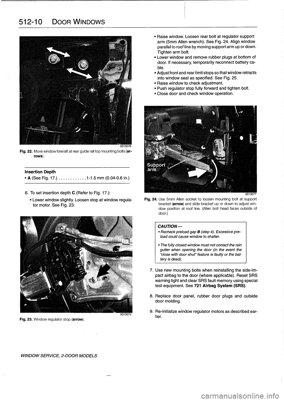
0013078
Fig
.
22
.
Move
window
fore/aftatrear
guide
rail
top
mounting
bolts
(ar-
rows)
.
Insertion
Depth
"
A
(See
Fig
.
17
.)
.
..........
.1-1
.5
mm
(0
.04-0
.6
in
.)
6
.
To
set
Insertion
depth
C
(Refer
to
Fig
.
17
.)
:
"
Lower
window
slightly
.
Loosen
stop
at
window
regula-
tor
motor
.
See
Fig
.
23
.
Fig
.
23
.
Window
regulator
stop
(arrow)
.
WINDOW
SERVICE,
2-DOOR
MODELS
0013075
"
Raise
window
.
Loosen
rear
boltat
regulator
support
arm
(5mm
Allen
wrench)
.
See
Fig
.
24
.
Align
window
parallelto
roof
line
by
moving
support
arm
up
or
clown
.
Tighten
arm
bolt
.
"
Lower
window
and
remove
rubber
plugs
at
bottom
of
door
.
If
necessary,temporarily
reconnect
battery
ca-
ble
.
"
Adjust
front
and
rear
limit
stops
so
that
window
retracts
into
window
seal
as
specified
.
See
Fig
.
25
.
"
Raise
window
to
check
adjustment
.
"
Push
regulator
stop
fully
forward
and
tighten
bolt
.
"
Closedoor
and
check
window
operation
.
0013077
Fig
.
24
.
Use
5mm
Afen
socket
to
loosen
mounting
boltat
support
bracket(arrow)
and
slide
bracket
up
or
clown
to
adjust
win-
dow
position
at
roof
line
.
(Allen
bolt
head
faces
outside
of
door
.)
CAUTION
-
"
Recheck
preload
gap
B
(step
4)
.
Excessive
pre-
load
could
cause
window
to
shatter
.
"
The
fully
closed
window
must
not
contact
the
rain
gutter
when
opening
the
door
(in
the
event
the
"close
with
door
shut"
feature
is
faulty
or
the
bat-tery
is
dead)
.
7
.
Usenew
mounting
bolts
when
reinstalling
the
side-im-
pact
airbag
to
the
door
(where
applicable)
.
Reset
SRS
warning
light
and
clear
SRS
fault
memory
using
special
test
equipment
.
See
721
Airbag
System
(SRS)
.
8
.
Replace
door
panel,
rubber
door
plugs
and
outside
doormolding
.
9
.
Re-initialize
window
regulator
motors
as
described
ear-
lier
.
Page 341 of 759
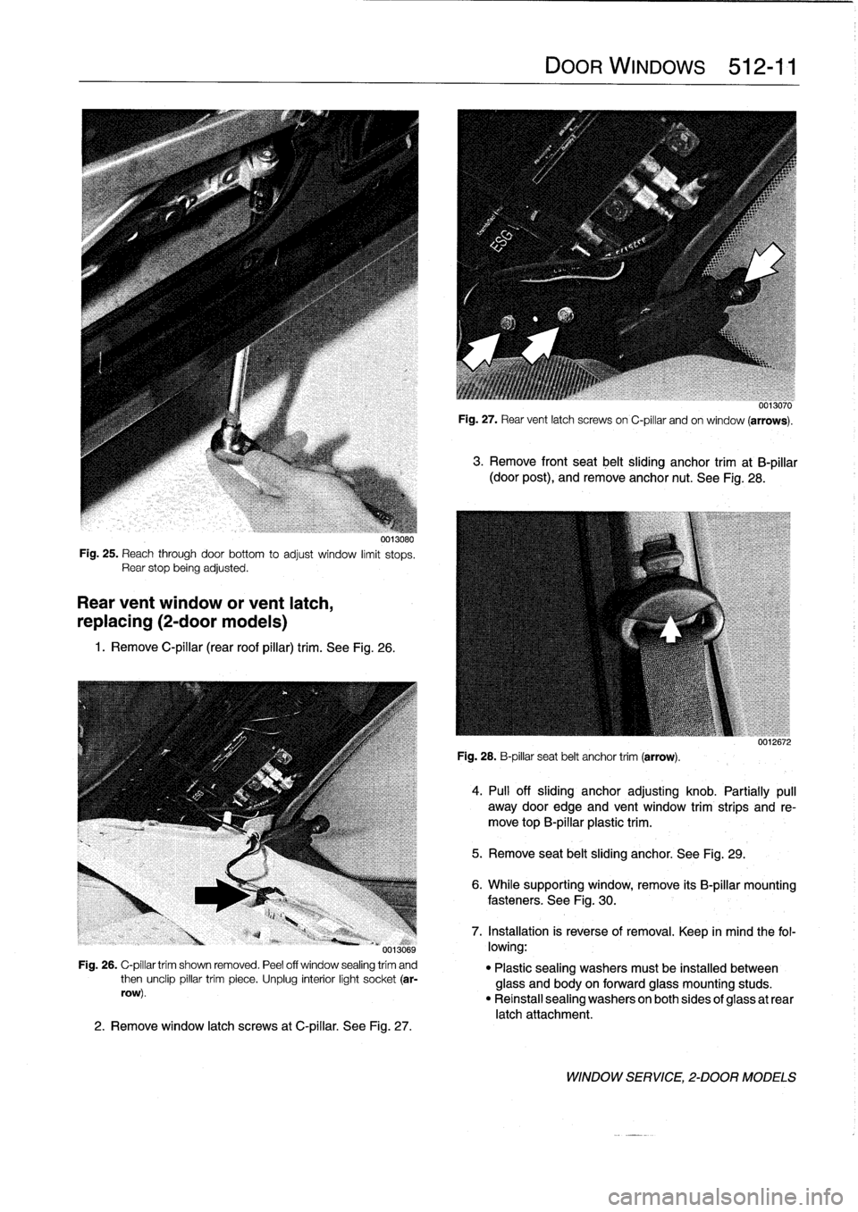
0013080
Fig
.
25
.
Reach
through
doorbottom
to
adjust
window
limit
stops
.
Rear
stop
beingadjusted
.
Rear
vent
window
or
vent
latch,
replacing
(2-door
modeis)
1
.
Remove
C-pillar
(rear
roof
pillar)
trim
.
See
Fig
.
26
.
0013069
Fig
.
26
.
C-pillar
trim
shown
removed
.
Peel
off
window
sealing
trím
and
then
unclip
pillar
trim
piece
.
Unplug
interior
light
socket
(ar-
row)
.
2
.
Remove
window
latch
screws
atC-pillar
.
See
Fig
.
27
.
DOOR
WINDows
512-11
0013070
Fig
.
27
.
Rear
vent
latch
screws
on
C-pillar
andon
window
(arrows)
.
3
.
Remove
front
seat
belt
sliding
anchor
trim
at
B-pillar
(door
post),
andremove
anchor
nut
.
See
Fig
.
28
.
Fig
.
28
.
B-pillar
seat
belt
anchor
trim
(arrow)
.
5
.
Remove
seat
belt
sliding
anchor
.
See
Fig
.
29
.
úulzoiz
4
.
PA
off
sliding
anchor
adjustíng
knob
.
Partially
pull
away
door
edge
and
vent
window
trimstrips
and
re-
move
top
B-pillar
plastic
trim
.
6
.
While
supporting
window,
remove
its
B-pillar
mounting
fasteners
.
See
Fig
.
30
.
7
.
Installation
is
reverseof
removal
.
Keep
in
mind
the
fol-
lowing
:
"
Plastic
sealing
washers
mustbe
installed
between
glass
and
body
on
forward
glass
mounting
studs
.
"
Reinstall
sealing
washers
on
both
sides
of
glass
at
rear
latch
attachment
.
WINDOW
SERVICE,
2-DOOR
MODELS
Page 345 of 759
GENERAL
This
repair
group
covers
interior
trim
removal
and
installa-
tion
procedures
.
Forremoval
and
installation
of
interior
switches,
including
interior
lighting
equipment,
see
612
Switches
and
Electrical
Accessories
.
Most
of
the
interior
trim
and
finish
paneis
are
clipped
or
screwed
into
place
.
Many
of
the
trim
retaining
clips
arede-
signed
to
be
used
only
once
.
When
removing
trim
that
is
held
in
place
with
clips,
it
is
a
good
idea
lo
have
spareson
hand
be-
fore
beginningthejob
.
CENTER
CONSOLE
The
front
section
center
console
houses
the
Multi-Informa-
tion
Display
(MID)
module,the
front
ashtray
and
cigarette
lighter
;
shifter
lever,
power
window
switches
and
the
hazard
warning
switch
.
The
rear
center
console
section
houses
the
ashtray(s)
and
covers
the
emergency
brakecable
ends
.
Center
console,
removing
and
installing
1
.
Disconnect
negative
(-)
cable
from
battery
and
cover
terminal
with
insulating
material
.
CA
UTION-
Prior
to
disconnectiog
the
battery,
read
the
battery
disconnection
cautionsgiven
at
the
front
of
this
manual
onpage
viii
.
2
.
Remove
shifter
boot
or
selectorlever
cover
.
See250
Gearshift
t-inkage
.
3
.
Remove
rear
ashtray
retaining
screws
totake
out
ash-
tray
.
Remove
rear
console
retaining
screwunder
ash-
tray
.
513
Interior
Tri
m
INTERIORTRIM
513-1
GENERAL
..
.
.....
.
.
.
.
.
.
.
.
.
.
.
......
.
.
.
513-1
DASHBOARD
.....
.
.
.
.
.
.
.
.
.
.
.
.
.
.
...
.
:
.
.513-2
Glove
compartment,removing
and
installing
.
.513-2
CENTER
CONSOLE
.
.
.
.
.
.
.
.
.
.
.........
513-1
Lower
left
dash
panel,
Center
console,
removing
and
installing
.....
513-1
removing
and
installing
.
.
.
.
.
.
.
.
.
.
.....
.
.
513-2
Dashboard,removing
and
installing
.
.
.
.
...
.
.513-3
4
.
Remove
Multi-Information
Display
module
.
See620
In-
struments
.
5
.
Remove
hazardwarning
switch
and
power
window
switches
bypushing
up
and
out
from
below
.
6
.
Remove
lower
left
dashboard
panel
and
glove
compart-
ment
as
described
later
in
this
repair
group
.
7
.
Remove
retaining
screwunder
hazard
light
switch
.
Pull
rear
console
back
and
remove
retaining
nut
at
back
of
front
console
.
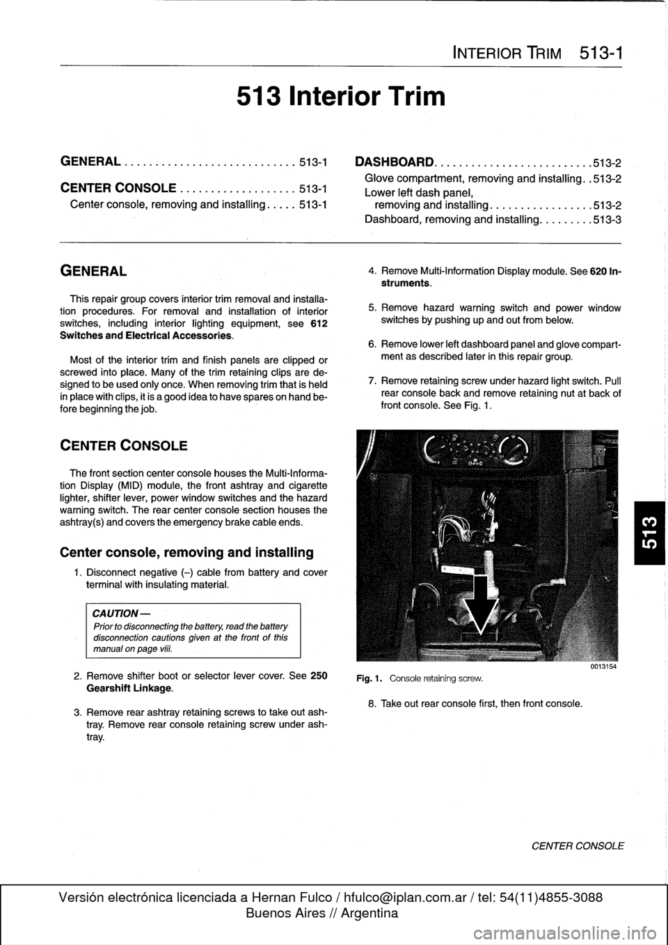
See
Fig
.
1
.
Fig
.1.
Console
retaining
screw
.
8
.
Take
out
rear
console
first,
then
front
console
.
0013154
CENTER
CONSOLE
Page 347 of 759
Dashboard,
removing
and
installing
1
.
Disconnect
negative
(-)
cable
from
battery
and
cover
terminal
with
insulating
material
.
CAUTION-
Prior
to
disconnectiog
the
battery,
read
the
battery
disconnection
cautionsgiven
at
the
front
of
this
manual
onpage
vi¡¡
.
2
.
Remove
center
console
as
described
earlier
.
3
.
Remove
glove
compartment
as
described
earlier
.
4
.
Remove
lower
left
dash
trim
piece
as
described
above
.
Remove
lower
right
dash
trim
panel
.
See
Fig
.
4
.
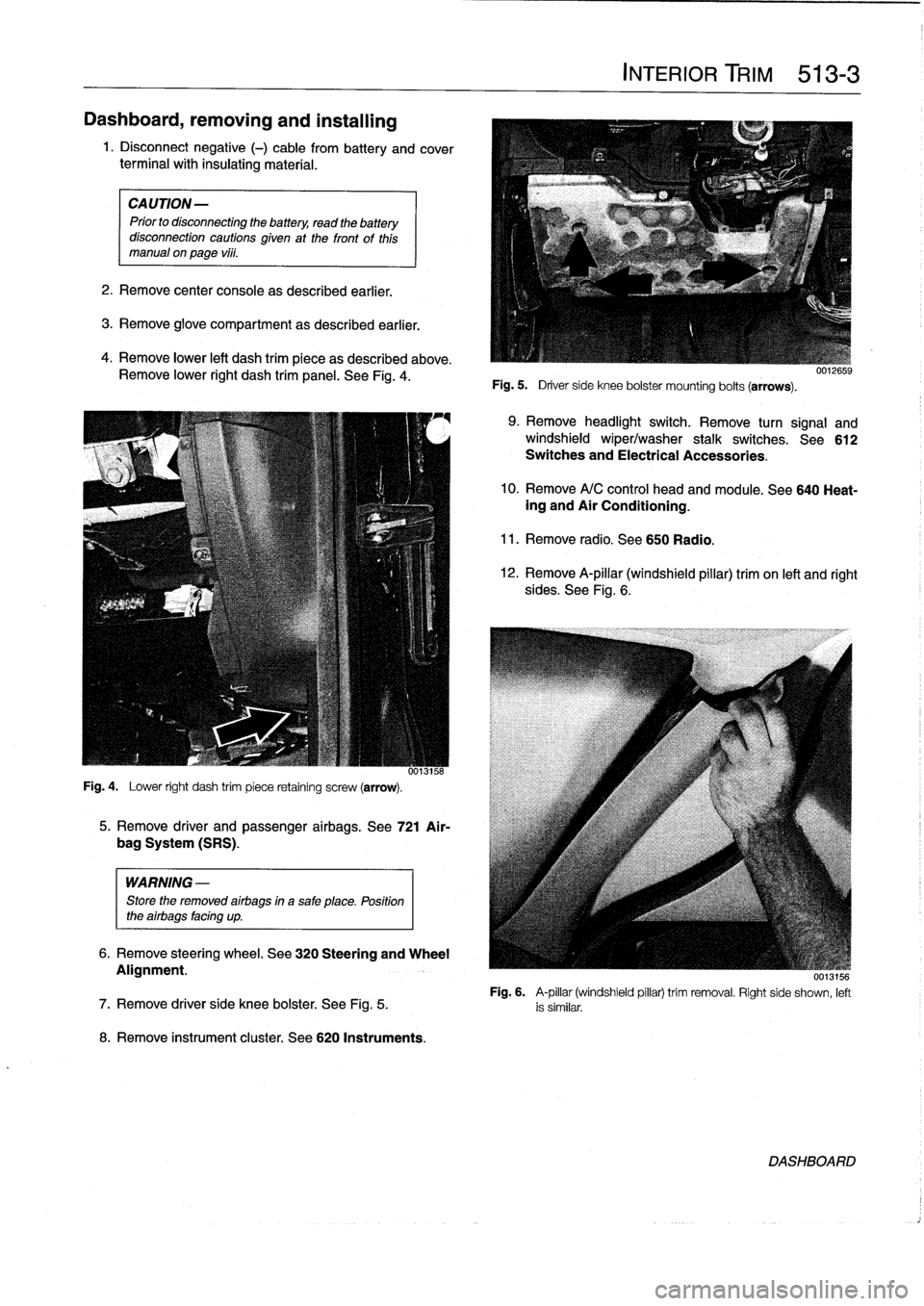
Fig
.
4
.
Lower
right
dash
trim
piece
retaining
screw
(arrow)
.
WARNING
-
Store
the
removed
airbags
in
a
safe
place
.
Position
the
airbags
facing
up
.
8
.
Remove
instrument
cluster
.
See
620
Instruments
.
5
.
Remove
driver
and
passenger
airbags
.
See
721
Air-
bag
System
(SRS)
.
6
.
Remove
steering
wheel
.
See
320
Steering
and
Wheel
Alignment
.
INTERIOR
TRIM
513-
3
Fig
.
5
.
Driver
side
knee
bolster
mounting
bolts
(arrows)
.
9
.
Remove
headlight
switch
.
Remove
turn
signal
and
windshield
wiper/washer
stalk
switches
.
See612
Switches
and
Electrical
Accessories
.
10
.
Remove
A/C
control
head
and
module
.
See
640
Heat-ing
and
Air
Conditioning
.
11
.
Remove
radio
.
See650
Radio
.
12
.
Remove
A-pillar
(windshield
pillar)
trim
on
left
and
right
sides
.
See
Fig
.
6
.
UU13156
Fig
.
6
.
A-pillar
(windshield
pillar)
trim
removal
.
Right
side
shown,
left
7
.
Remove
driver
side
knee
bolster
.
See
Fig
.
5
.
is
similar
.
DASHBOARD
Page 348 of 759
513-
4
INTERIOR
TRIM
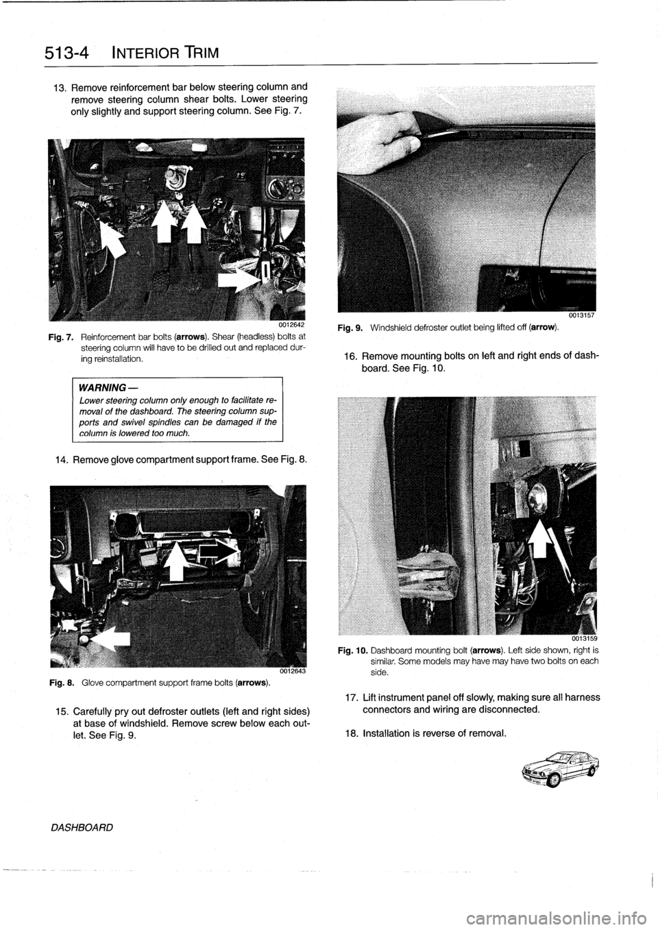
13
.
Remove
reinforcement
bar
below
steering
column
and
remove
steering
column
shear
bolts
.
Lower
steering
only
slightly
and
support
steering
column
.
See
Fig
.
7
.
WARNING
-
Lower
steering
column
only
enough
to
facilitate
re-
moval
of
the
dashboard
.
The
steering
column
sup-
ports
and
swivel
spindles
canbe
damaged
if
the
column
is
lowered
too
much
.
14
.
Remove
glove
compartment
support
frame
.See
Fig
.
8
.
0012643
Fig
.
8
.
Glove
compartment
support
frame
bolts
(arrows)
.
DASHBOARD
0013157
Fig
.
9
.
Windshield
defroster
outlet
being
lifted
off
(arrow)
.
Fig
.
7
.
Reinforcementbar
bolts
(arrows)
.
Shear
(headless)
bolts
at
steering
column
will
have
to
be
drilled
out
and
replaceddur-
ing
reinstallation
.
16
.
Remove
mounting
bolts
on
left
and
right
ends
of
dash-
board
.
See
Fig
.
10
.
Fig
.
10
.
Dashboard
mounting
bolt
(arrows)
.
Left
side
shown,
right
is
similar
.
Some
models
may
have
may
have
two
bolts
oneach
side
.
17
.
Lift
instrument
panel
off
slowly,
making
sure
all
harness
15
.
Carefullypryout
defroster
outlets
(left
and
right
sides)
connectors
and
wiring
are
disconnected
.
a
t
base
of
windshield
.
Remove
screwbelow
each
out-
let
.
See
Fig
.
9
.
18
.
Installation
is
reverse
of
removal
.
Page 350 of 759
515-2
CENTRAL
LOCKING
AND
ANTI-THEFT
0013117
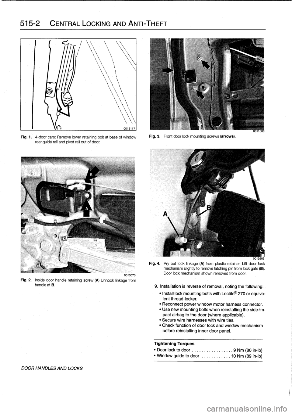
Fig
.
1
.
4-door
cars
:
Remove
lower
retaining
boltat
base
of
window
rear
guide
rail
and
pivot
rail
out
of
door
.
Fig
.
3
.
Front
door
lock
mounting
screws
(arrows)
.
uu11686
0012685
Fig
.
4
.
Pry
out
locklinkage
(A)
from
plastic
retainer
.
Lift
door
lock
mechanism
slightly
to
Rmove
latching
pin
from
lock
gate
(B)
.
Door
lock
mechanism
shown
removed
from
door
.
0013073
Fig
.
2
.
Inside
door
handle
retaining
screw
(A)
Unhook
linkage
from
handle
at
B
.
9
.
Installation
is
reverse
of
removal,
noting
the
following
:
DOOR
HANDLES
AND
LOCKS
"
Install
lock
mounting
bolts
with
Loctite
0
270
or
equiva-
lent
thread-locker
.
"
Reconnect
power
window
motor
harness
connector
.
"
Usenew
mounting
bolts
when
reinstalling
the
side-ím-
pact
airbag
to
the
door
(where
applicable)
.
"
Secure
wire
harnesses
with
wire
ties
.
"
Check
function
of
door
lock
and
window
mechanism
before
reinstalling
inner
door
panel
.
Tightening
Torques
"
Door
lock
to
door
......
.
..........
9
Nm
(80
in-lb)
"
Window
guide
to
door
........
.
...
10
Nm
(89
in-lb)
Page 351 of 759
![BMW M3 1992 E36 Workshop Manual
Front
door
handle,
removing
and
installing
1
.
Closedoor
window
completely
.
2
.
Remove
front
door
panel
and
vapor
barrier
asde-
scribed
in
411
Doors
.
WARNING
-
Some
1997
and
al]
1998
cars
are
f BMW M3 1992 E36 Workshop Manual
Front
door
handle,
removing
and
installing
1
.
Closedoor
window
completely
.
2
.
Remove
front
door
panel
and
vapor
barrier
asde-
scribed
in
411
Doors
.
WARNING
-
Some
1997
and
al]
1998
cars
are
f](/img/1/2800/w960_2800-350.png)
Front
door
handle,
removing
and
installing
1
.
Closedoor
window
completely
.
2
.
Remove
front
door
panel
and
vapor
barrier
asde-
scribed
in
411
Doors
.
WARNING
-
Some
1997
and
al]
1998
cars
are
fitted
with
side-im-
pact
airbags
in
the
front
doors
.
When
servicing
the
door
handles
on
cars
with
front
side-impact
airbags,
always
disconnect
the
negative
(-)
battery
terminal
.
See
721
Airbag
System
(SRS)
for
cautions
and
pro-
cedures
relatíng
to
the
airbag
system
.
3
.
On
carswíth
side-impact
airbags,
disconnect
negative
(-)
cable
from
battery,
then
remove
airbag
module
.
CAUTION-
Prior
to
disconnecting
the
battery,
read
the
battery
disconnection
cautions
given
at
the
front
of
thís
manual
onpage
vi¡¡
.
NOTE-
In
some
models
covered
inthis
manual,
it
is
not
essen-
tial
to
remove
the
side-impact
airbag
to
access
internal
door
components
.
However,
the
procedure
is
recom-
mended
for
safety
reasons
.
4
.
Remove
door
lock
as
described
earlier
.
5
.
Remove
window
as
described
in
512
Door
Windows
.
CA
UTION-
On
models
with
side-impact
airbags,
removinglin-
stalling
the
front
window
requires
that
the
battery
cable
bereconnected
wíth
the
side-impact
airbag
disconnected
.
This
will
seta
fault
code
in
the
SRS
control
module,
turn
on
the
SRS
warning
light,
and
disable
the
SRS
system
until
the
fault
memo-
ry
is
cleared
usíng
special
SRS
test
equipment
.
6
.
Pry
out
access
plug
in
end
of
door
.
Use
screwdriver
through
access
hole
to
slide
exteriortrim
locking
plate
into
released
position
.
See
Fig
.
5
.
Remove
doorhandle
exterior
trim
piece
.
7
.
Working
inside
door,
remove
locking
clip
for
doorhan-
dle
retaining
pin
and
push
pin
out
.
8
.
Working
inside
door,
disconnect
electrical
harness
con-
nector
at
door
handle
.
Twist
plastic
connector
bracket
to
remove
from
door
handle
.
CENTRAL
LOCKING
AND
ANTI-THEFT
515-
3
0011681
Fig
.
5
.
Insert
screwdriver
into
access
hole
and
push
lockingplate
forward
(arrow)
to
release
exterior
handle
trim
.
uu11682
Fig
.
6
.
Door
handle
retaining
pin(A)
and
lock
collar
nut
(B)
.
Door
handle
trim
shown
removed
.
10
.
Remove
door
handle
fromdoor
by
angling
out
of
door
cavity
.
Removed
door
handle
assembly
is
shown
in
Fig
.
7
.
0012684
Fig
.
7
.
Door
handle
harnessconnector
(A)
;
retaining
pin
Iocking
clip
9
.
Working
at
door
exterior,
remove
handle
collar
nut
(B)
;
exterior
trim
Iocking
plate
(C)
.
Handleassembly
shown
re-
while
supporting
handle
.
See
Fig
.
6
.
moved
from
door
.
DOOR
HANDLES
AND
LOCKS
Page 352 of 759
515-4
CENTRAL
LOCKING
AND
ANTI-THEFT
11
.
Installation
is
reverse
of
removal
.
Keep
in
mind
the
fol-
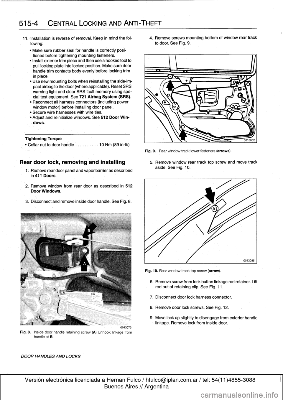
4
.
Remove
screws
mounting
bottom
of
window
rear
track
lowing
:
to
door
.
See
Fig
.
9
.
"
Make
sure
rubber
seal
for
handle
is
correctly
posi-
tionedbefore
tightening
mounting
fasteners
.
"
Install
exteriortrim
piece
and
then
use
a
hooked
tool
to
pull
locking
plate
into
locked
position
.
Make
sure
door
handle
trim
contacts
body
evenly
before
locking
trim
in
place
.
"
Use
new
mounting
bolts
when
reinstalling
the
side-im-
pactairbag
to
the
door(where
applicable)
.
Reset
SRS
warning
light
and
clear
SRS
fault
memory
using
spe-
cial
test
equipment
.
See
721
Airbag
System
(SRS)
.
"
Reconnect
al¡
harness
connectors
(including
power
window
motor)before
installing
door
panel
.
"
Secure
wire
harnesses
withwire
ties
.
"
Adjust
and
reinitialize
windows
.
See
512
Door
Win-
dows
.
Tightening
Torque
"
Collar
nut
to
doorhandle
..........
10
Nm
(89
in-lb)
1.
Remove
rear
door
panel
and
vapor
barrier
as
described
in
411
Doors
.
2
.
Remove
window
from
rear
dooras
described
in
512
Door
Windows
.
3
.
Disconnect
andremove
inside
door
handle
.
See
Fig
.
8
.
0013073
Fig
.
8
.
Inside
door
handle
retaining
screw
(A)
Unhook
linkage
from
handle
at
B
.
DOOR
HANDLES
AND
LOCKS
Fig
.
9
.
Rear
window
track
lower
fasteners
(arrows)
.
Reardoor
lock,
removing
and
installing
5
.
Remove
window
rear
track
top
screw
and
move
track
aside
.
See
Fig
.
10
.
Fig
.
10
.
Rear
window
track
top
screw
(arrow)
.
6
.
Remove
screw
from
lock
button
linkage
rod
retainer
.
Lift
rod
out
of
retaining
clip
.
See
Fig
.
11
.
7
.
Disconnect
door
lock
harnessconnector
.
8
.
Remove
door
lock
screws
.
See
Fig
.
12
.
0013085
9
.
Move
lock
upslightly
to
disengage
from
exterior
handle
linkage
.
Remove
lock
from
inside
door
.
Page 355 of 759
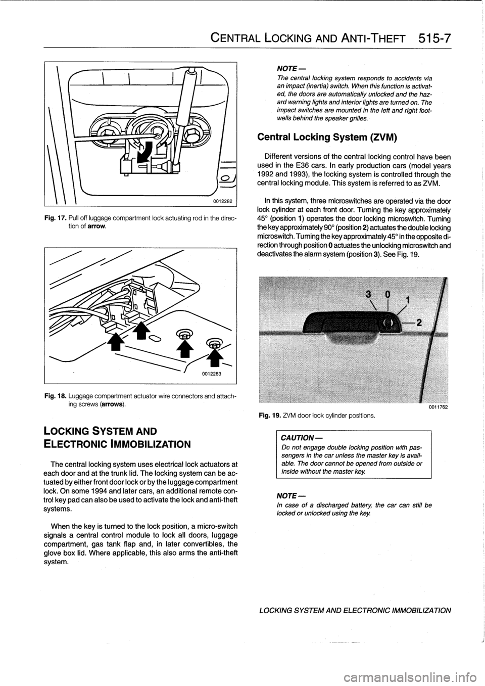
002262
In
this
system,
three
microswitches
are
operated
via
the
door
lock
cylinder
at
each
front
door
.
Turning
the
key
approximately
Fig
.
17
.
Pufl
off
luggage
compartment
lock
actuating
rod
in
the
direc-
45°
(position
1)
operates
the
door
locking
microswitch
.
Tuming
tionof
arrow
.
the
key
approximately
90°
(position2)
actuates
the
double
locking
microswitch
.
Tuming
the
key
approximately
45°
in
the
opposite
di-
rection
through
position
0
actuates
the
unlocking
microswitch
and
deactivates
the
alarm
system
(position3)
.
See
Fig
.
19
.
Fig
.
18
.
Luggage
compartment
actuatorwire
connectors
and
attach-
ing
screws
(arrows)
.
LOCKING
SYSTEM
AND
ELECTRONIC
IMMOBILIZATION
The
central
locking
system
uses
electrical
lock
actuators
at
each
door
and
at
the
trunk
lid
.
The
locking
system
can
be
ac-
tuated
by
either
front
door
lock
or
by
the
luggage
compartment
lock
.
Onsome
1994
and
later
cars,
an
additional
remote
con-
trol
keypadcan
also
be
used
to
activate
the
lock
and
anti-theft
systems
.
When
the
key
is
tuned
to
the
lock
position,
a
micro-switch
signals
a
central
control
module
to
lock
all
doors,
luggage
compartment,
gas
tank
flap
and,
in
later
convertibles,
the
glove
box
lid
.
Where
applicable,
this
also
arms
the
anti-theft
system
.
CENTRAL
LOCKING
AND
ANTI-THEFT
515-7
NOTE-
The
central
locking
system
responds
to
accidents
vía
animpact
(inertia)
switch
.
When
this
function
ís
activat-
ed,
the
doors
are
automatically
unlocked
and
the
haz-
ard
warning
lights
and
interiorlights
are
turned
on
.
The
impact
switches
are
mounted
in
the
left
and
right
foot-
wells
behind
the
speaker
grilles
.
Central
Locking
System
(ZVM)
Different
versions
of
the
central
locking
control
havebeen
used
in
the
E36
cars
.
In
early
production
cars
(model
years
1992
and
1993),
the
locking
system
is
controlled
through
the
central
locking
module
.
This
system
is
referred
to
as
ZVM
.
Fig
.
19
.
ZVM
door
lock
cylinderpositíons
.
CAUTION-
Do
not
engage
double
locking
position
with
pas-
sengers
in
the
car
unless
the
master
key
isavail-
able
.
The
door
cannotbe
opened
from
outside
orinside
without
the
master
key
.
NOTE-
In
case
of
a
discharged
battery,
the
car
can
still
be
locked
orunlocked
using
the
key
.
0011762
LOCKING
SYSTEM
AND
ELECTRONIC
IMMOBILIZATION
Page 368 of 759
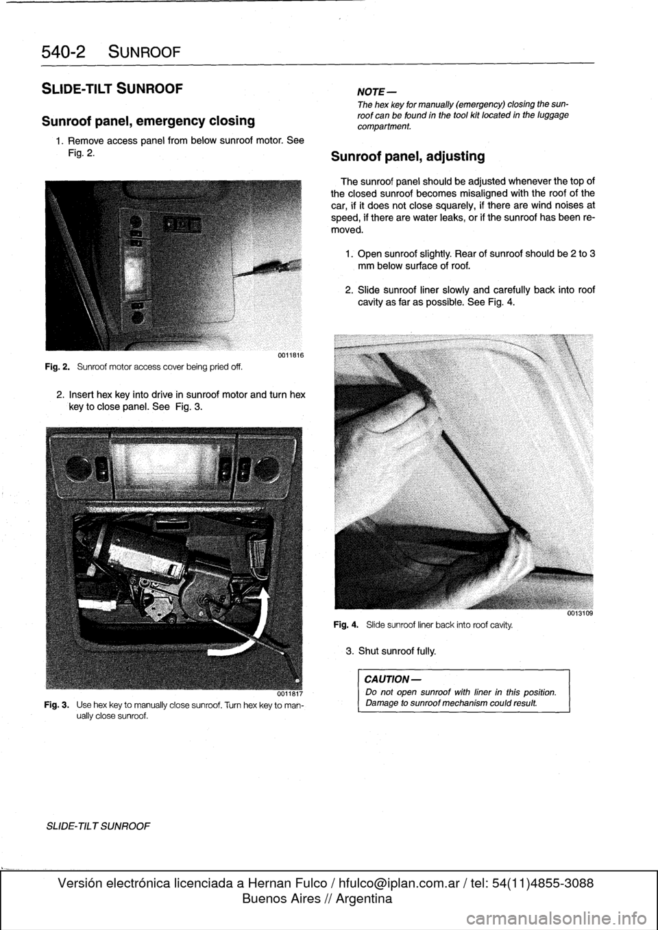
540-2
SUNROOF
SLIDE-TILT
SUNROOF
Sunroof
panel,
emergency
closing
1.
Remove
access
panel
frombelow
sunroof
motor
.
See
Fig
.
2
.
Fig
.
2
.
Sunroof
motor
access
coverbeing
pried
off
.
0011816
2
.
Insert
hex
key
into
drive
in
sunroof
motor
and
turn
hex
key
to
Glosepanel
.
See
Fig
.
3
.
SLIDE-TILT
SUNROOF
0~i18r7
Fig
.
3
.
Use
hexkey
to
manually
Glose
sunroof
.
Turn
hexkey
to
mah-
ually
Glose
sunroof
.
NOTE-
The
hex
key
for
manually
(emergency)
closing
the
sun-
roof
canbe
found
in
the
tool
kit
located
in
the
luggage
compartment
.
Sunroof
panel,
adjusting
The
sunroof
panel
should
be
adjusted
whenever
thetop
of
the
closed
sunroof
becomes
misaligned
with
the
roof
of
the
car,
ifit
does
not
Glosesquarely,
if
there
arewind
noises
at
speed,
if
there
arewater
leaks,
or
if
the
sunroof
has
been
re-
moved
.
1
.
Open
sunroof
slightly
.
Rear
of
sunroof
should
be
2
to
3
mm
below
surface
of
roof
.
2
.
Slide
sunroof
liner
slowly
and
carefully
back
into
roof
cavity
as
far
as
possible
.
See
Fig
.
4
.
Fig
.
4
.
Slide
sunroof
liner
back
into
roof
cavity
.
3
.
Shut
sunroof
fully
.
CAUTION
-
Do
not
open
sunroof
with
liner
inthis
position
.
Damage
to
sunroof
mechanism
could
result
.