E36 1996 BMW M3 1993 E36 Workshop Manual
[x] Cancel search | Manufacturer: BMW, Model Year: 1993, Model line: M3, Model: BMW M3 1993 E36Pages: 759
Page 15 of 759
Non-returnable
Parts
FUNDAMENTALS
FOR
THEDO-ITYOURSELF
OWNER
010-
7
Many
independent
repair
shops
make
a
point
of
using
genu-
Original
body
paneis
and
other
large
components
are
identi-
ine
BMW
parts,
even
though
they
may
at
times
be
more
expen-
fied
by
a
label
bearing
the
VINand
two
BMW
roundellogos
.
Re-
sive
.
Theyknow
the
value
of
doing
thejob
right
with
the
right
placement
parts
have
a
similar
label,
bearing
one
BMW
roundel
parts
.
Parts
from
other
sources
can
beas
good,
particularly
if
logo
and
the
letters
DOT-R
.
See
Fig
.
6
.
Parts
or
assemblies
manufactured
by
one
of
BMWs
original
equipment
suppliers,
bearing
the
label
arethe
engine,
transmission,
front
and
rear
but
it
is
often
difficult
to
know
.
bumpers,
front
fenders,
rear
quarter
paneis,
hood,
trunk
lid
and
doors
.
These
labels
shouldnot
be
removed
as
they
will
tear
BMW
is
constantly
updating
and
improving
their
cars,
often
apart
.
making
improvements
during
a
given
model
year
.
BMW
may
recommend
a
newer,
improved
part
as
a
replacement,
and
your
authorized
dealer's
parts
department
will
know
about
it
and
provide
it
.
The
BMW
parts
organization
is
best
equipped
to
deal
with
any
BMW
parts
needs
.
Some
parts
cannot
be
returned
for
credit,
even
if
they
arethe
wrong
parts
forthe
car
.
The
best
example
is
electrical
parts,
which
are
almost
universally
considered
non-returnable
be-
,
..
cause
they
are
so
easily
damaged
internally
.
Buy
electrícal
parts
carefully,
and
beas
sure
as
possible
that
P-
DOT~
R
a
replacement
is
needed,
especially
for
expensive
parts
such
as
electronic
control
units
.
It
may
bewise
to
let
an
authorized
B328FUN
BMW
dealeror
other
qualified
shop
confirm
your
diagnosisbe-
fore
replacing
an
expensive
part
that
cannot
be
retuned
.
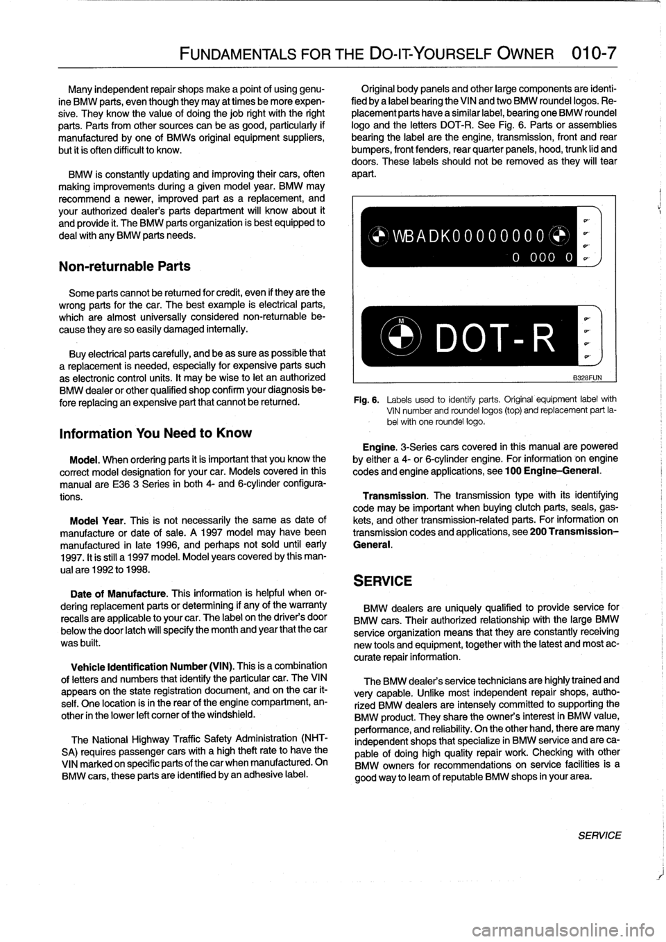
Fig
.
6
.
Labels
used
to
identiy
parts
.
Original
equipment
labelwith
VIN
number
and
roundel
logos
(top)
and
replacement
part
la-
bel
with
one
roundel
logos
Information
You
Need
to
Know
Engine
.
3-Seriescars
covered
in
this
manualare
powered
Model
.
When
ordering
parts
it
is
important
that
you
know
the
by
either
a
4-or
6-cylinder
engine
.
For
information
-
on
engine
correct
model
designation
for
your
car
.
Models
covered
in
this
codes
and
engine
applications,
see100
Engine-General
.
manual
are
E36
3
Series
in
both
4-
and
6-cylinderconfigura-
tions
.
Transmission
.
The
transmissiontype
with
its
identifying
code
may
be
important
when
buying
clutch
parts,
seals,
gas
Moda¡
Year
.
This
is
not
necessarily
the
same
as
date
of
kets,
and
othertransmission-relatedparts
.
For
information
on
manufacture
or
date
of
sale
.
A
1997
model
may
havebeen
transmission
codes
and
applications,
see200
Transmission
manufactured
in
late
1996,
and
perhaps
not
sold
until
early
General
.
1997
.
It
is
still
a1997
model
.
Model
years
covered
by
this
man-
ual
are
1992
to
1998
.
SERVICE
Date
of
Manufacture
.
This
information
is
helpful
when
or-
dering
replacement
parts
or
determining
if
any
of
the
warranty
BMW
dealers
are
uniquely
qualified
to
provide
service
for
recalls
are
applicable
to
your
car
.
The
label
on
the
driver's
door
BMW
cars
.
Their
authorized
relationship
with
the
large
BMW
below
the
door
latch
will
specify
the
month
and
year
that
the
car
serviceorganization
means
that
they
are
constantly
receiving
was
built
.
new
tools
and
equipment,
together
with
the
latest
and
most
ac-
curate
repair
information
.
Vehicle
Identification
Number
(VIN)
.
This
is
a
combination
of
letters
and
numbers
that
identify
the
particular
car
.
TheVIN
appears
on
the
state
registration
document,
and
on
thecar
it-
self
.
One
location
isin
the
rear
of
the
engine
compartment,
en-
other
in
the
lower
left
comer
of
the
windshield
.
The
National
Highway
Traffic
Safety
Administration
(NHT-
SA)
requires
passenger
cars
with
a
high
theftrateto
have
the
VINmarked
on
specific
parts
of
thecar
when
manufactured
.
On
BMW
cars,
these
parts
are
identified
byan
adhesive
label
.
)WBADK00000000
0
000
0
The
BMW
dealers
service
technicians
are
highlytrained
and
very
capable
.
Unfke
most
independent
repair
shops,
autho-
rized
BMW
dealers
are
intensely
committed
tosupporting
the
BMW
product
.
They
share
the
owners
interest
in
BMW
value,
performance,
and
reliability
.
On
the
other
hand,
there
are
many
independent
shops
that
specialize
in
BMW
service
and
are
ca-
pable
of
doing
high
quality
repair
work
.
Checking
with
other
BMW
owners
for
recommendations
on
service
facilitiesis
a
good
way
to
leam
of
reputable
BMW
shops
in
yourarea
.
SERVICE
Page 43 of 759
GENERAL
.
.....
.
.
.
.
.
.
.
...
.
.
.
.
.
.
.
.
.
...
100-1
Cylinder
Block
and
Crankshaft
.
.
.
.
.
.
.
.
.
...
100-1
Connecting
Rods
and
Pistons
.
.
.
.
.
.
.
.
.
.
.
.
.
100-1
Cylinder
Head
and
Valvetrain
.
.
.
.
.
.
.
.
.
.
.
.
.
100-2
VANOS
(Variable
Valve
Timing)
.
.
.
.
.
.
.
.
...
100-2
DISA
(Dual
Resonance
Intake
System)
.
.
.
.
.
100-3
Engine
Management
System
.
.
.
.
.
.
.
.
.
.
.
.
.
100-3
Ignition
......
.
.
.
.........
.
.
.
.
.
.
.
.
.
.
.
.
100-5
Fuel
Delivery
..
.
.
.
.....
.
...
.
.
.
.
.
.
.
.
.
.
.
.
100-5
Cooling
System
.
...........
.
.
.
.
.
.....
.
.
100-5
Lubrication
System
.........
.
.
.
.
.
.
.
.
.
.
.
.
100-5
MECHANICALTROUBLESHOOTING
.
.
.
.
100-5
Warnings
and
Cautions
..
.
...
.
.
.
.
.
.
.
.
.
.
.
.
100-5
Cylinder
compression,
checking
.
.
.
.
.
.
.
.
.
.
.
100-6
EngineMechanical
Troubleshooting
Table
.
.
.
100-7
DRIVEABILITY
TROUBLESHOOTING
...
100-8
GENERAL
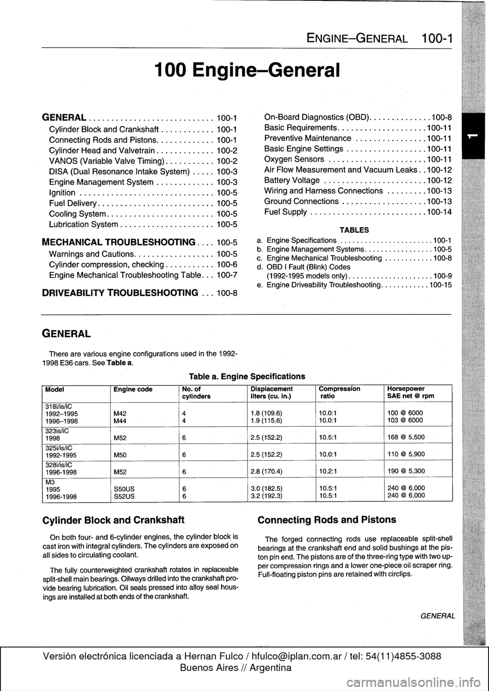
There
are
various
engíne
configurations
used
in
the
1992-
1998
E36
cars
.
See
Table
a
.
On
both
four-
and
6-cylinder
engines,
the
cylinder
block
is
cast
¡ron
with
integral
cyiinders
.
The
cyiinders
are
exposed
on
all
sides
to
circulating
coolant
.
The
fully
counterweighted
crankshaft
rotates
in
replaceable
split-shell
main
bearings
.
Oiiways
drilled
into
the
crankshaft
pro-
vide
bearing
lubrication
.
O¡I
seals
pressed
into
alloy
sea¡
hous-
ings
are
installedat
both
ends
of
the
crankshaft
.
100
Engine-General
Tablea
.
Engine
Specifications
ENGINE-GENERAL
100-1
On-Board
Diagnostics
(OBD)
...
.
.
.
.
.
.
.
.
.
.
.
100-8
Basic
Requirements
....
.
.
.
...
.
.
.
.
.
....
.100-11
Preventive
Maintenance
......
.
.
.
.
.
.....
100-11
Basic
Engine
Settings
..
.
.....
.
.
.
.
.
.....
100-11
Oxygen
Sensors
.
.
.
...
.
.
.
...
.
.
.
.
.
....
.100-11
Air
Flow
Measurement
and
Vacuum
Leaks
.
.100-12
Battery
Voltage
.
.
...........
.
.
.
.
.
.....
100-12
Wiring
and
Harness
Connections
.
.
.
.
.....
100-13
Ground
Connections
...
.
.....
.
.
.
.
.
.....
100-13
Fue¡
Supply
....
.
...........
.
.
..
.....
.100-14
TABLES
a
.
Engine
Specifications
...
...
...........
.
..
..
.100-1
b
.
Engine
Management
Systems
..
..
...........
..
100-5
c
.
Engine
Mechanical
Troubleshooting
..........
.
.
100-8
d
.
OBD
1
Fault
(Blink)
Codes
(1992-1995
models
only)
.
...
..
..
..........
..
.100-9
e
.
Engine
Driveability
Troubleshooting
...........
.100-15
Model
Engine
code
No
.
of
Dispiacement
Compression
Horsepower
cyiinders
liters
(cu
.
in
.)
ratio
SAE
net
@
rpm
318i/is/¡C
1992-1995
M42
4
1
.8
(109
.6)
10
.0
:1
100
@
6000
1996-1998
M44
4
1
.9
(115
.6)
~
10
.0
:1
103
@
6000
323ís/iC
1998
M52
6
2
.5
(152
.2)
10
.5
:1
168
@
5,500
325i/is/iC
1992-1995
M50
6
2
.5
(152
.2)
10
.0
:1
110
@
5,900
328i/is/iC
1996-1998
M52
6
2
.8
(170
.4)
10
.2
:1
190
@
5,300
M3
1995
S50US
6
3
.0
(182
.5)
10
.5:1
240
@
6,000
1996-1998
S52US
6
3
.2
(192
.3)
10
.5:1
240
@
6,000
Cylinder
Block
and
Crankshaft
Connecting
Rods
and
Pistons
The
forged
connecting
rods
use
replaceable
split-shell
bearings
at
the
crankshaft
endand
solid
bushings
at
the
pis-
ton
pin
end
.
The
pistonsare
of
the
three-ring
typewith
two
up-
per
compression
rings
and
a
lowerone-piece
o¡i
scraper
ring
.
Fui¡-floating
piston
pins
are
retained
with
circlips
.
GENERAL
Page 46 of 759
100-4
ENGINE-GENERAL
'
TEMP
PRECAT
POST
CAT
OXYGENSENSOR
HEATING
#
.
THROTTLE
POSITION
FUEL
INJECTOR
CONTROL
(SEQUENTIAL)
OPERATING
POWER
00
CAMSHAFT
POSITION
SENSOR
ECM
I
MAIN
GROUND
RELAY
J_
-
AC
COMPRESSOR
RELAY
CONTROL
TERMINAL
15
MEMORY
POWER
FUEL
PUMP
RELAY
CONTROL
AUX
GROUND
P
CRANKSHAFT
POSITION
dESENSOR
INTAKE
AIR
ENGINE
COOLANT
TEMP
FUEL
TANK
PRESSURE
SENSOR
S-EML
S-MSR
ASC
S-ASC
VEHICLE
SPEED
LOW
FUEL
LEVEL
A/C
SWITCH
ON
(AC)
E36
IHKA
COMPRESSOR"ON"
SIGNAL
(KO)
INDIVIDUAL
SERIAL
NUMBER
MS41
.1
SECONDARY
AIR
1NJECTION
AIR
PUMP®
RELAY
CONTROL
IDLE
CONTROL
VALVE
'M
FUEL
INJECTION
(TI)
ENGINE
SPEED
(TD)
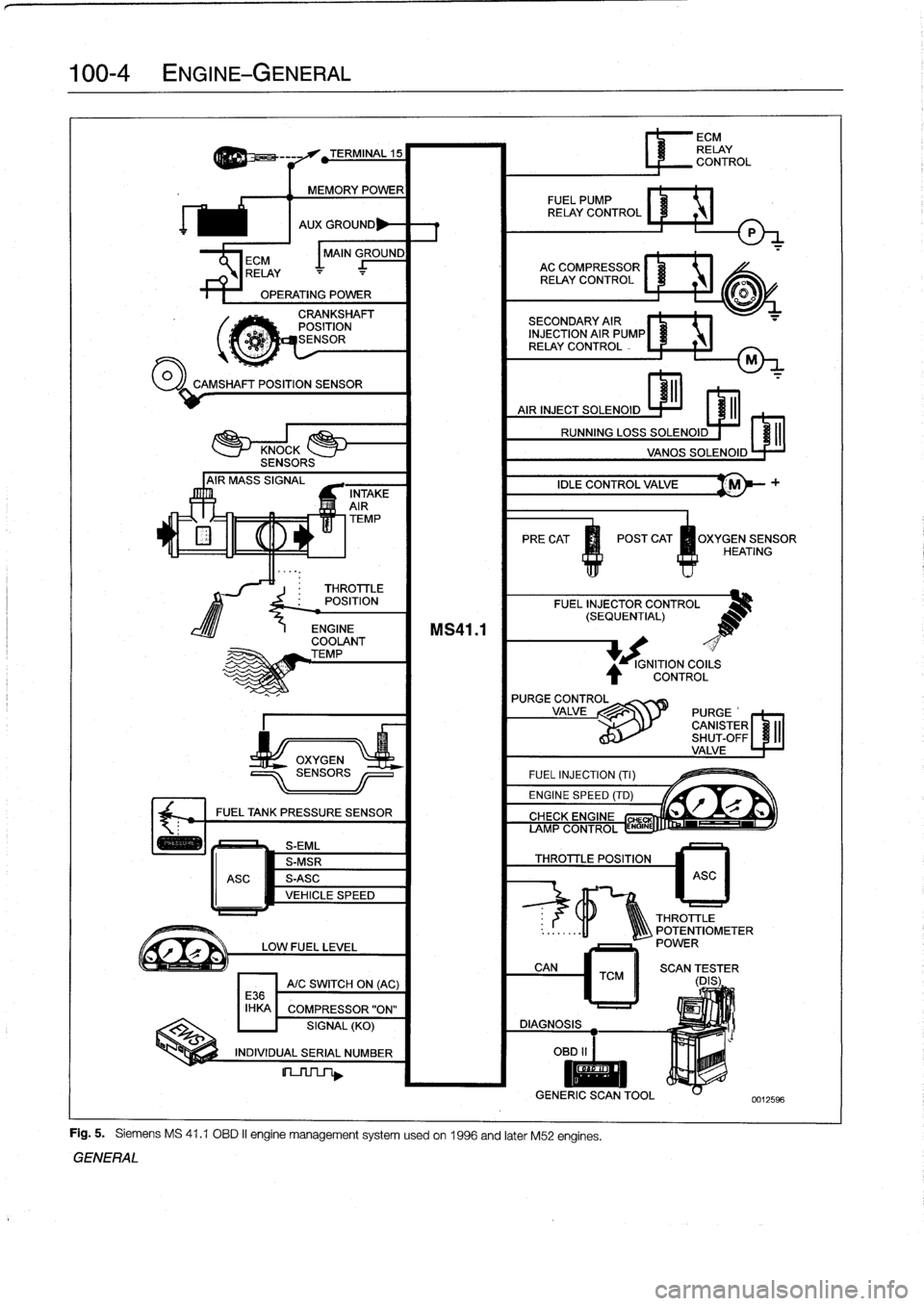
Fig
.
5
.
Siemens
MS
41
.1
OBD
II
engine
management
systemusedon
1996
and
later
M52
engines
.
GENERAL
IGNITION
COILS
CONTROL
L
r"Q
if~
CIYVFIYC
CHE
AMP
CONTROL
ENGINE
THROTTLE
POSITION
6
ECM
RELAY
CONTROL
ASC
THROTTLE
..
:
.
.
..
-11
1Q\\\
POTENTIOMETER
POWER
CAN
TCM
II
SCAN
(DES
;
ER
DIAGNOSIS
OBD
II
I
II
GENERIC
SCANTOOL
0012596
Page 148 of 759
130-2
FUEL
INJECTION
GENERAL
This
repair
group
covers
fuel
injection
system
component
testing
and
repair
.
Special
equipment
is
necessary
for
some
of
the
procedures
given
in
this
repair
group
.
If
you
do
not
have
the
equipment
required
to
do
the
job,
it
is
recommended
that
these
repairs
be
left
to
an
authorized
BMW
dealer
.
The
BMW
dealer
is
equipped
with
sophisticated
diagnostic
test
equip-
ment
that
is
capable
of
quicklypinpointing
hard-to-find
fuel
in-
jection
problems
.
NOTE-
"
Wiring
diagrams
for
the
engine
management
system,
can
be
found
at
the
rear
of
the
manual
under
Electri-
cal
Wiring
Diagrams
.
"
For
ignition
system
repairinformation,
see120
Igni-
tion
System
.
"
For
fuel
supply
system
testing
and
repair,
see160
The
engine
control
module
(ECM)
uses
electrical
signals
Fuel
Tank
and
Fuel
Pump
.
from
the
mass
air
flow
sensor,
the
air
and
coolant
temperature
sensors,
the
crankshaft
position/rpm
sensor,
the
knock
sen
Principies
Of
Operation
sors
and
the
oxygen
sensorsas
the
primary
inputs
to
electron-
ically
control
fuel
delivery
and
ignition
timing
.
There
are
five
versions
of
engine
management
systems
usedon
the
E36
cars
.
Each
has
the
same
basic
components
and
operating
principles
.
The
most
notable
difference
is
that
1996
and
later
cars
use
a
sophisticated
OBD
II-compliant
sys-
tem
.
See
Table
a
.
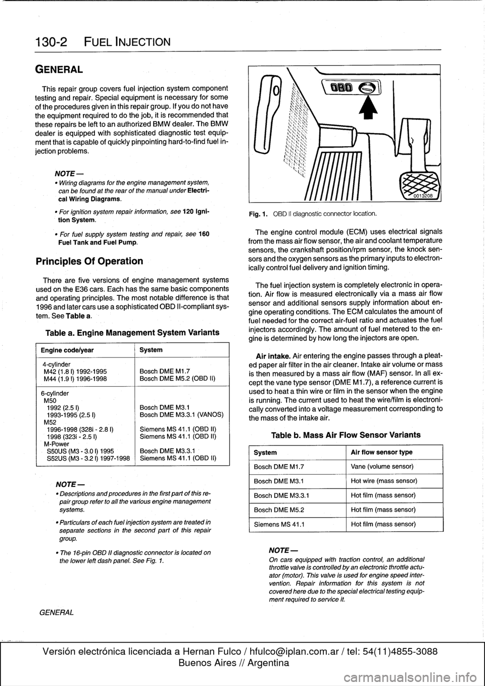
Table
a
.
Engine
Management
System
Variants
Engine
code/year
1
System
4-cy1inder
M42
(1
.8
I)
1992-1995
Bosch
DME
Ml
.7
M44
(1
.91)
1996-1998
~
Bosch
DME
M5
.2
(OBD
II)
6-cylinder
M50
1992
(2.5
I)
Bosch
DME
M3
.1
1993-1995
(2.5
I)
Bosch
DME
M3
.3.1
(VANOS)
M52
1996-1998
(3281-
2
.8
I)
Siemens
MS
41
.1
(OBD
II)
1998
(3231
-
2
.5
I)
Siemens
MS
41
.1
(OBD
II)
M-Power
S50US
(M3
-
3
.01)
1995
Bosch
DME
M3
.3
.1
S52US
(M3
-
3
.21)
1997-1998
Siemens
MS
41
.1
(0131)
11)
NOTE-
-
Descriptions
and
procedures
in
the
first
partof
this
re-
pairgroup
refer
to
all
the
various
engine
management
systems
.
"
Particulars
of
each
fuel
injection
system
are
treated
in
separate
sections
in
the
second
part
of
this
repair
group
.
GENERAL
Fig
.1
.
OBD
II
diagnostic
connector
locatíon
.
The
fuel
injection
system
is
completely
electronic
in
opera-
tion
.
Air
flow
is
measured
electronically
via
a
mass
air
flow
sensor
and
additional
sensors
supply
information
about
en-
gine
operating
conditions
.
The
ECM
calculates
the
amount
of
fuel
needed
for
the
correct
air-fuel
ratio
and
actuates
the
fuel
injectors
accordingly
.
The
amount
offuel
metered
to
theen-
gine
is
determined
by
how
long
the
injectors
are
open
.
Airintake
.
Air
entering
the
engine
passes
through
a
pleat-
ed
paper
air
filter
in
the
air
cleaner
.
Intake
air
volume
or
mass
is
then
measured
bya
mass
air
flow
(MAF)
sensor
.
In
al¡
ex-
cept
the
vane
type
sensor
(DME
M1
.7),
a
reference
current
is
used
to
heat
a
thin
wireor
film
in
the
sensor
when
the
engine
is
running
.
The
current
used
to
heat
the
wire/film
is
electroni-
cally
converted
into
a
voltage
measurement
corresponding
to
the
mass
of
the
intake
air
.
Table
b
.
Mass
Air
Flow
Sensor
Variants
System
Al
r
flow
sensor
type
Bosch
DME
M1
.7
Vane
(volume
sensor)
Bosch
DME
M3
.1
Hot
wire
(mass
sensor)
Bosch
DME
M3
.3
.1
Hot
film
(mass
sensor)
Bosch
DME
M5
.2
Hot
film
(mass
sensor)
Siemens
MS
41
.1
Hot
film
(mass
sensor)
"
The
16-pin
OBD
11
diagnostic
connector
is
located
on
NOTE-
the
lower
left
dashpanel
.
See
Fig
.
1
.
On
cars
equipped
wíth
tractioncontrol,
an
additional
throttle
valve
is
controlled
by
an
electronic
throttle
actu-
ator
(motor)
.
This
valve
is
used
for
engine
speed
inter
vention
.
Repair
information
forthis
system
is
notcovered
here
due
to
the
special
electrical
testing
equip-
ment
required
to
service
it
.
Page 149 of 759
FUEL
INJECTION
130-
3
Fuel
metering
.
The
ECM
meters
fuel
bychanging
the
The
engine
management
system
compensates
automatical-
opening
time
(pulsewidth)
of
the
fuel
injectors
.
To
ensure
that
ly
for
changes
in
the
engine
due
to
age,
minor
wear
or
small
injector
pulsewídth
is
the
only
factor
that
determines
fuel
me-
problems,
such
as
a
disconnected
vacuum
hose
.
Asa
result,
tering,fuel
pressure
is
maintained
bya
fuel
pressure
regula-
idle
speed
and
mixture
do
not
need
lo
be
adjustedas
partof
tor
.
The
injectors
are
mounted
lo
a
common
fuel
supply
called
routine
maintenance
.
the
fuel
rail
.
The
ECM
monitors
engine
speed
to
determine
the
duration
NOTE-
ofinjector
openings
.
Other
signals
to
the
ECM
help
determine
Poordriveabilitymaybe
encountered
when
the
batteryis
injector
pulse
time
for
different
operating
conditions
.
A
tem-
disconnected
and
reconnected
.
when
the
battery
is
dis-
connected,
the
adaptive
memory
is
lost
The
system
will
perature
sensor
signals
engine
temperature
for
mixture
adap-
readaptafterabout
ten
minutes
of
drfving
.
tion
.
A
throttle
position
sensor
signals
throttle
position
.
The
exhaust
oxygen
sensor(s)
signal
information
about
combus-
tion
efficiency
for
control
of
the
air-fuel
mixture
.
1992
to
1995
DISA
(Dual
Resonance
Intake
System)
engines
are
equipped
with
a
single
sensor
.
1996
and
later
(OBD
II)
engines
are
equipped
with
an
oxygen
sensor
before
TheE36
4-cylinder
engine
is
equipped
with
a
dual
intake
andone
after
each
catalytic
converter
.
Forexample,the
M52
runner
system,
termed
DISA
.
DISA
offers
the
advantages
of
engine
is
equipped
withfour
oxygen
sensors
.
both
short
and
long
intake
pipes
.
Long
intake
runners
are
most
useful
at
low
to
medium
engine
rpm
for
producing
good
Idle
speed
control
.
ldle
speed
is
electronically
controlled
torque
characteristics
.
Short
intake
runners
produce
hígherviathe
idle
speed
control
valve,
which
maintains
idle
speed
by
horsepower
at
hígher
engine
speeds
.
bypassing
varying
amounts
of
air
around
theclosed
throttle
valve
.
Idle
speed
is
not
adjustable
.
NOTE-
Knock
(detonation)
control
.
Knock
sensors
monitor
and
The
term
DISA
comes
from
the
German
words
Differen-
control
ignition
knock
through
the
ECM
.
The
knock
sensors
zierte
Sauganlage,
and
can
roughlybe
translated
as
"dif-
fering
intake
manifold
configuration
."
See
100
Engine-
function
like
microphones
and
are
able
to
convert
mechanical
General
foradditional
information
on
DISA
operation
.
vibration
(knock)
into
electrical
signals
.
The
ECM
is
pro-
grammed
to
react
to
frequencies
that
are
characteristic
of
en-
Manifold
construction
:
The
intake
manifold
is
a
two-piece
gine
knock
and
adapt
the
ignition
timing
point
accordingly
.
metal
construction,
with
a
pair
of
runners
in
thetop
section
See120
Ignition
System
for
further
details
.
and
four
runners
in
the
lower
section
.
A
butterfly
valve
is
in-
stalled
in
the
lower
section,
enabling
the
DISA
solenoid
toiso-
NOTE-
late
one
pair
of
runners
from
the
other
pair
.
See
Fig
.
2
.
The
1992
M50
engine
is
not
equipped
with
knock
sen-
Operation
.
With
the
DISA
butterfly
valve
closed,
the
pipes
sors
.
All
other
engines
are
equipped
with
two
knock
in
thetop
half
of
the
manifold
act
together
with
the
ram
air
sensors
.
pipes
in
the
lower
halfto
producea
single,
long
air
intake
pipe
for
each
cylinder
.
See
Fig
.
3
.
The
column
of
aír
oscíllating
in
Basic
Engine
Settings
this
combined
pipe
significantly
increases
engine
torque
in
the
medium
rpm
range
.
Idle
speed,
idle
mixture
(%CO),
and
ignition
timing
arenot
adjustable
.
The
adaptive
engine
management
system
is
de-
signed
to
automatically
compensate
for
changes
in
engine
op-
eratingconditions,
although
the
adaptive
range
is
limited
.
Once
these
limits
are
exceeded,
driveability
problems
usually
be-
come
noticeable
.
Above
approximately
4,800
rpm,
the
butterfly
valve
between
the
intake
air
pipes
for
the
two
cylinder
groups
is
opened
.
The
shorter
pipes
in
the
lower
manifold
section
now
become
the
main
suppliers
of
ram
air
to
the
cylinders,yielding
greater
pow-
er
at
the
upper
end
of
the
engine
rpm
range
.
See
Fig
.
4
.
Control
components
.
The
DISA
butterfly
valve
is
actuated
NOTE-
electro-pneumatically
via
the
engine
control
module
(ECM)
.
lf
the
system
adaptive
limits
are
exceeded,
the
Check
The
valve
begins
to
open
as
engine
speed
rises
aboye
4,840
Engine
light
will
most
likely
come
on,
indicating
an
rpmand
closes
below
4,760
rpm
.
The
action
of
the
valve
is
de-
emissions-
related
fault
For
Check
Engine
light
diag-
liberately
delayed
to
prevent
it
from
opening
and
closing
repeat-
nostics,
see100
Engine-General
.
edly
within
a
short
time
.
GENERAL
Page 159 of 759
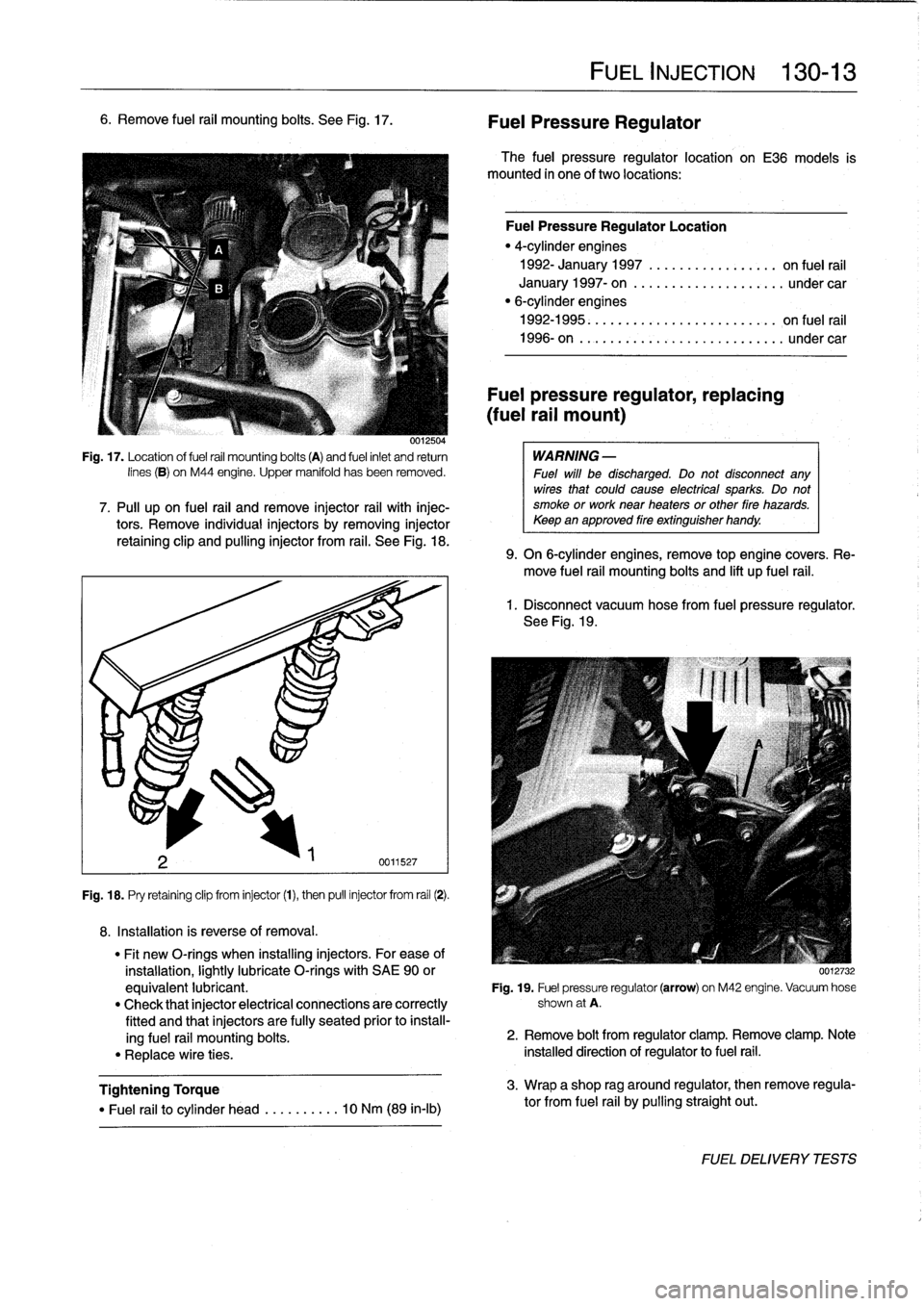
6
.
Remove
fuel
rail
mounting
bolts
.
See
Fig
.
17
.
0012504
Fig
.
17
.
Location
of
fuel
rail
mounting
bolts
(A)
and
fuel
inlet
and
return
lines
(B)
on
M44
engine
.
Upper
manifold
has
been
removed
.
7
.
Pull
upon
fuel
rail
and
remove
injector
rail
with
injec-tors
.
Remove
individualinjectors
by
removing
injector
retaining
clip
and
pullinginjector
from
rail
.
See
Fig
.
18
.
Fig
.
18
.
Pry
retaining
clip
from
injector
(1),
then
pull
injector
from
rail
(2)
.
8
.
Installation
is
reverse
of
removal
.
Tightening
Torque
"
Fuel
rail
to
cylinder
head
..
.
..
..
...
10
Nm
(89
in-lb)
FUEL
INJECTION
130-
1
3
Fuel
Pressure
Regulator
The
fuel
pressure
regulator
location
on
E36
models
is
mounted
in
one
of
two
locations
:
Fuel
Pressure
Regulator
Location
"
4-cylinder
engines
1992-
January
1997
............
...
..
on
fuel
rail
January
1997-
on
...............
..
...
under
car
"
6-cylinderengines
1992-1995
.
.
...
...
.
...........
...
..
on
fuel
rail
1996-on
..
.
..
................
...
...
undercar
Fuel
pressure
regulator,
replacing
(fuel
rail
mount)
WARNING
-
Fuel
will
be
discharged
.
Do
not
disconnect
any
wires
that
could
cause
electrícal
sparks
.
Do
not
smoke
or
work
near
heaters
or
other
fire
hazards
.
Keepan
approved
fire
extinguisher
handy
.
9
.
On
6-cylinder
engines,
remove
top
engine
covers
.
Re-
move
fuel
rail
mounting
bolts
and
lift
up
fuel
rail
.
1
.
Disconnect
vacuum
hose
from
fuel
pressure
regulator
.
See
Fig
.
19
.
"
Fit
new
O-rings
when
installing
injectors
.
For
ease
of
installation,
lightly
lubricate
O-rings
with
SAE
90
or
0012732
equivalent
lubricant
.
Fig
.
19
.
Fuel
pressure
regulator
(arrow)
on
M42
engine
.
Vacuum
hose
"
Check
that
injector
electrical
connections
are
correctly
shown
at
A
.
fitted
and
that
injectors
are
fully
seated
prior
to
install-
ing
fuel
rail
mounting
bolts
.
2
.
Remove
bolt
from
regulator
clamp
.
Remove
clamp
.
Note
"
Replace
wire
ties
.
installed
direction
of
regulator
to
fuel
rail
.
3
.
Wrap
a
shop
rag
around
regulator,
then
remove
regula-
tor
from
fuel
rail
by
pulling
straight
out
.
FUELDELIVERYTESTS
Page 186 of 759
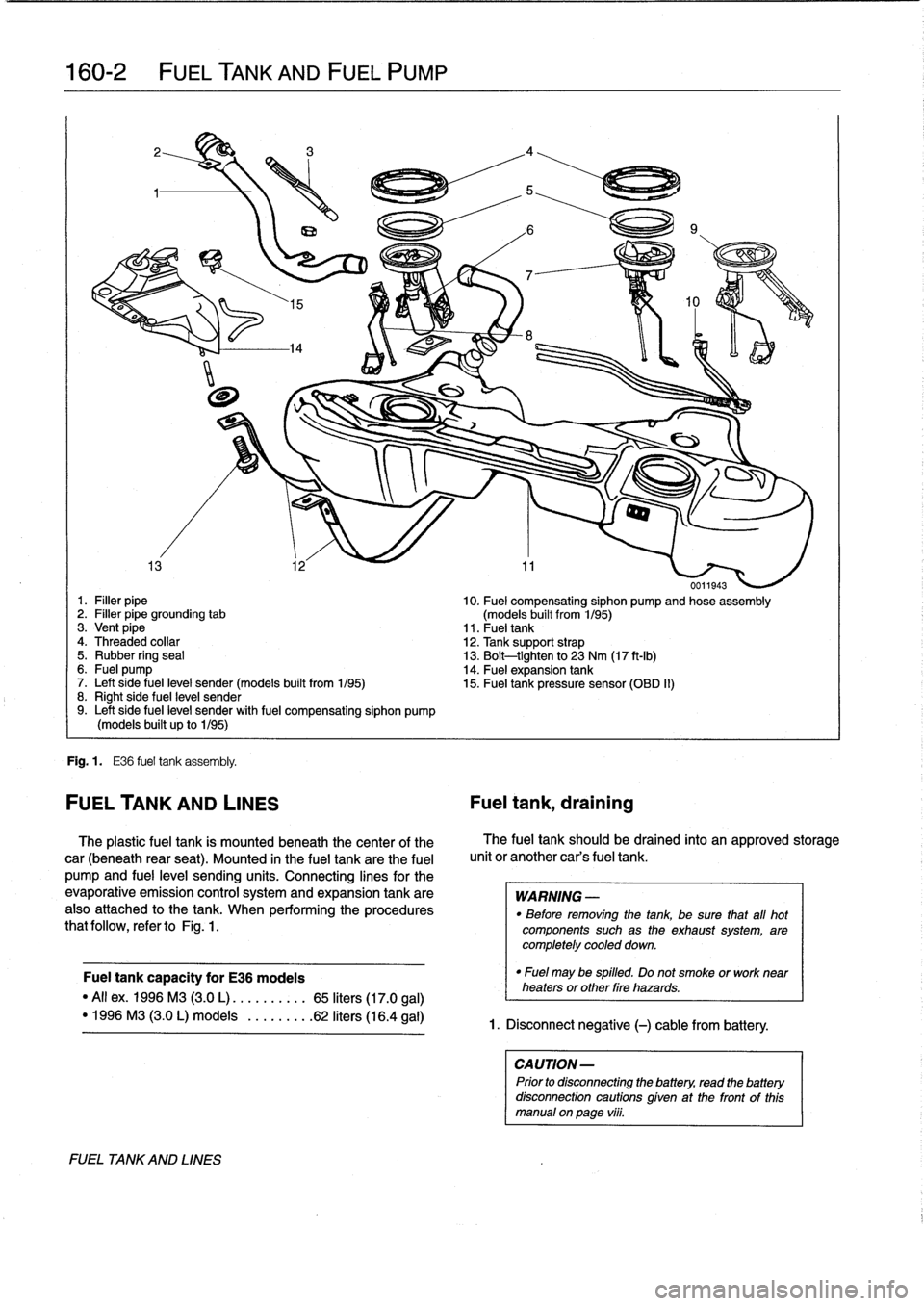
160-2
FUEL
TANK
AND
FUEL
PUMP
0011943
1
.
Filler
pipe
10
.
Fuel
compensating
siphon
pump
and
hose
assembly
2
.
Filler
pipe
grounding
tab
(models
built
from
1/95)
3
.
Vent
pipe
11
.
Fueltank
4
.
Threaded
collar
12
.
Tank
support
strap
5
.
Rubber
ring
seal
13
.
Bolt-tighten
to
23
Nm
(17
ft-Ib)
6
.
Fuel
pump
14
.
Fuel
expansion
tank
7
.
Left
side
fuel
leve¡
sender(models
built
from
1/95)
15
.
Fuel
tank
pressure
sensor
(OBD
II)
8
.
Right
side
fuel
leve¡
sender9
.
Left
side
fuel
leve¡
sender
with
fuel
compensating
siphon
pump
(models
built
up
to
1/95)
Fig
.
1
.
E36
fuel
tank
assembly
.
FUEL
TANK
AND
LINES
Fuel
tank,
draining
The
plastic
fuel
tank
is
mounted
beneath
the
center
of
the
car
(beneath
rear
seat)
.
Mounted
in
the
fuel
tank
are
the
fuel
pump
and
fuel
leve¡
sending
units
.
Connecting
lines
for
the
evaporative
emission
control
systemand
expansion
tank
are
also
attached
to
the
tank
.
When
performing
the
procedures
that
follow,
refer
toFig
.
1
.
Fuel
tank
capacity
for
E36
modeis
"All
ex
.
1996
M3
(3
.0
L)
.....
.
..
..
65
liters
(17
.0
gal)
"
1996
M3
(3.0L)
modeis
.
...
.
..
.
.62
liters
(16
.4
gal)
FUEL
TA
NKAND
LINES
The
fuel
tank
should
be
drained
into
an
approved
storage
unit
or
another
car's
fuel
tank
.
WARNING
-
"
Before
removing
the
tank,
be
sure
that
afl
hot
components
such
as
the
exhaust
system,
are
completely
cooled
down
.
"
Fuel
may
be
spilled
.
Do
not
smoke
or
worknear
heaters
or
other
Pire
hazards
.
1
.
Disconnect
negative
(-)
cable
from
battery
.
CAUTION-
Prior
to
disconnectiog
the
battery,
read
the
battery
disconnection
cautions
given
at
the
front
of
this
manual
on
paga
vi¡¡
.
Page 188 of 759
160-
4
FUEL
TANK
AND
FUEL
PUMP
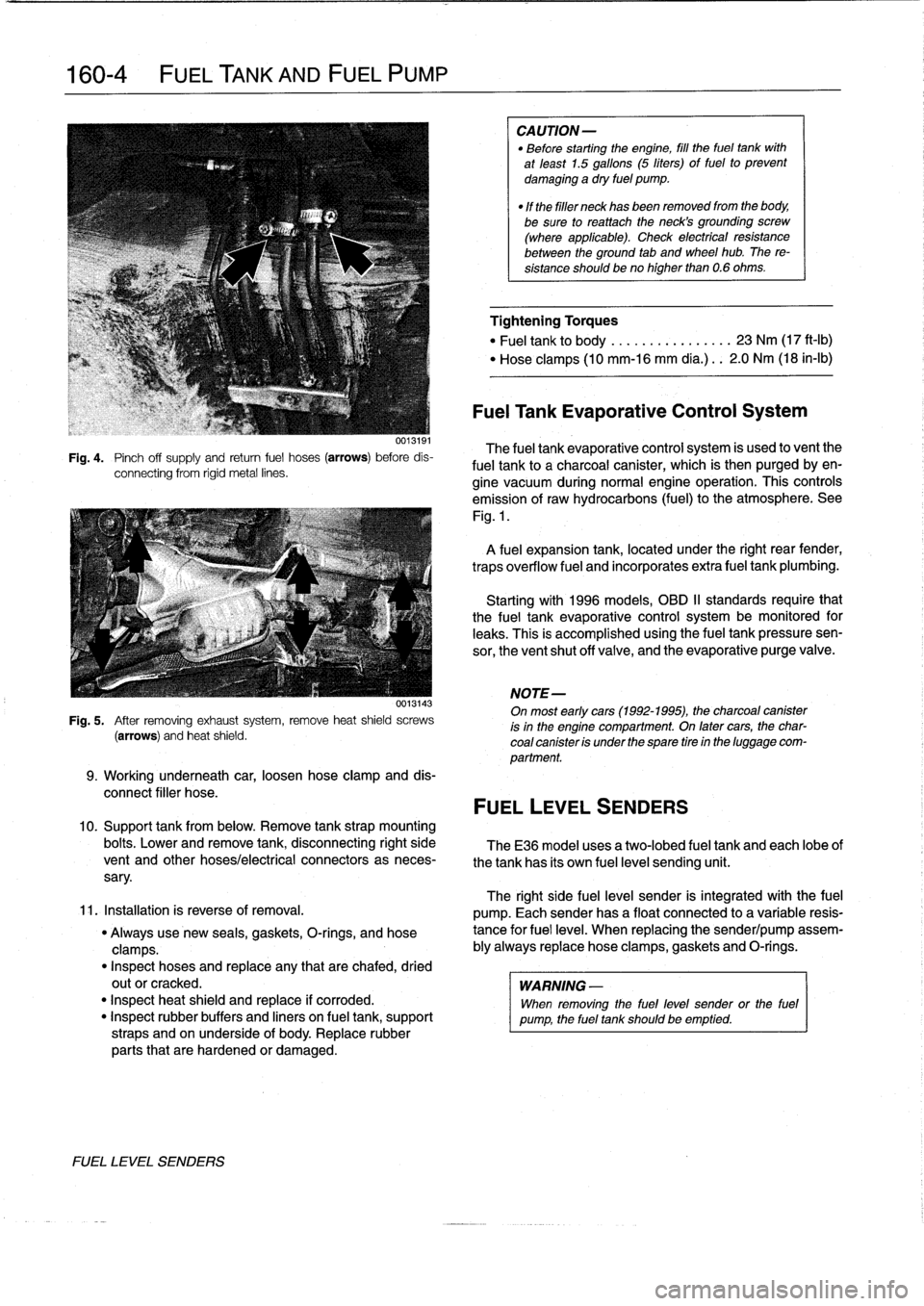
Fig
.
4
.
Pinch
off
supply
and
retum
fuel
hoses
(arrows)
before
dis-
connecting
from
rigid
metal
lines
.
0013143
Fig
.
5
.
After
removing
exhaustsystem,
remove
heat
shield
screws
(arrows)
and
heat
shield
.
9
.
Working
underneath
car,
loosen
hose
clamp
and
dis-
connect
filler
hose
.
10
.
Support
tank
from
below
.
Remove
tank
strap
mounting
bolts
.
Lower
and
remove
tank,
disconnecting
right
side
TheE36
model
uses
a
two-lobed
fuel
tank
and
each
lobeof
vent
and
other
hoses/electrical
connectors
as
neces-
the
tank
has
its
own
fuel
level
sending
unit
.
sary
.
11
.
Installation
is
reverse
of
removal
.
"
Always
use
new
seals,
gaskets,
O-rings,
and
hose
clamps
.
"
Inspect
hoses
and
replace
any
that
are
chafed,
dried
outor
cracked
.
"
Inspect
heat
shield
and
replace
if
corroded
.
"
Inspect
rubber
buffers
and
liners
on
fuel
tank,
support
straps
and
on
underside
of
body
.
Replace
rubber
parts
that
are
hardened
or
damaged
.
FUEL
LEVEL
SENDERS
CAUTION-
"
Before
starting
the
engine,
fill
the
fuel
tank
with
at
least
1.5
gallons
(5
liters)
of
fuel
to
prevent
damaging
a
dry
fuel
pump
.
"
If
the
filler
neck
has
been
removed
from
the
body,
be
sure
toreattach
theneck's
grounding
screw
(where
applicable)
.
Check
electrical
resistance
between
the
ground
tab
and
wheel
hub
.
The
re-
sistance
shouldbeno
higher
than
0
.6
ohms
.
Tightening
Torques
"
Fuel
tank
to
body
.............
...
23
Nm
(17
ft-Ib)
"
Hose
clamps
(10
mm-16
mm
día
.)
..
2
.0
Nm
(18
in-lb)
Fuel
Tank
Evaporative
Control
System
The
fuel
tank
evaporative
control
system
is
used
to
vent
the
fuel
tank
to
a
charcoal
canister,
which
is
then
purgedby
en-
gine
vacuum
during
normal
engine
operatíon
.
This
controls
emission
of
raw
hydrocarbons
(fuel)
to
the
atmosphere
.
See
Fig
.
1
.
A
fuel
expansion
tank,
located
under
the
right
rear
fender,
traps
overflow
fuel
and
incorporates
extra
fuel
tank
plumbing
.
Startingwith
1996
models,
OBD
II
standards
require
that
the
fuel
tank
evaporative
control
system
be
monitored
for
leaks
.
This
is
accomplished
usingthe
fuel
tankpressuresen-
sor,
the
ventshut
off
valve,
and
the
evaporative
purge
valve
.
NOTE-
On
most
early
cars(1992-1995),
the
charcoal
canister
is
in
the
engine
compartment
.
On
latercars,
the
char-
coal
canister
is
under
the
spare
tire
in
the
luggage
com-
partment
.
FUEL
LEVEL
SENDERS
The
right
side
fuel
leve¡
sender
is
integrated
with
the
fuel
pump
.
Each
senderhas
a
float
connected
to
a
variable
resis-
tance
for
fuel
leve¡
.
When
replacing
the
sender/pump
assem-
bly
always
replace
hose
clamps,gaskets
and
O-rings
.
WARNING
-
When
removing
the
fuel
level
sender
or
the
fuel
pump,
the
fuel
tank
should
be
emptied
.
Page 213 of 759
GENERAL
..
.
......
.
.
.
.....
.
...
.
.
.
.
.
.
.
.
200-1
Manual
Transmission
.
.
.....
.
.
.
.'
.
.
.
.
.
.
.
.
200-1
Automatic
Transmission
.........
.
.
.
.
.
.
.
.
200-1
Transmission
ID
Codes
..........
.
.
.
.
.
.
.
.
200-2
GENERAL
E36
models
areequipped
with
a
longitudinal
drivetrain
.
The
transmission
is
bolted
directly
to
the
rear
of
the
engine
.
A
driveshaft
connects
the
output
shaft
of
thetransmission
to
the
final
drive
.
The
final
drive
is
mounted
lo
the
rear
suspension
and
the
body
.
Individual
drive
axles
with
integrated
constant
velocity
joints
transfer
rotational
power
to
the
rear
wheels
.
Manual
Transmission
Due
to
different
power
characteristics
and
performance
re-
quirements,
four
different
manual
transmissions
are
used
in
the
models
coveredby
this
manual
.
Manual
transmission
ap-
plications
are
given
in
Table
a
.
TRANSMISSION-GENERAL
200-1
200
Transmission-General
TABLES
a
.
Manual
Transmission
Applications
..
...........
200-1
b
.
Automatic
Transmission
Applications
...........
200-1
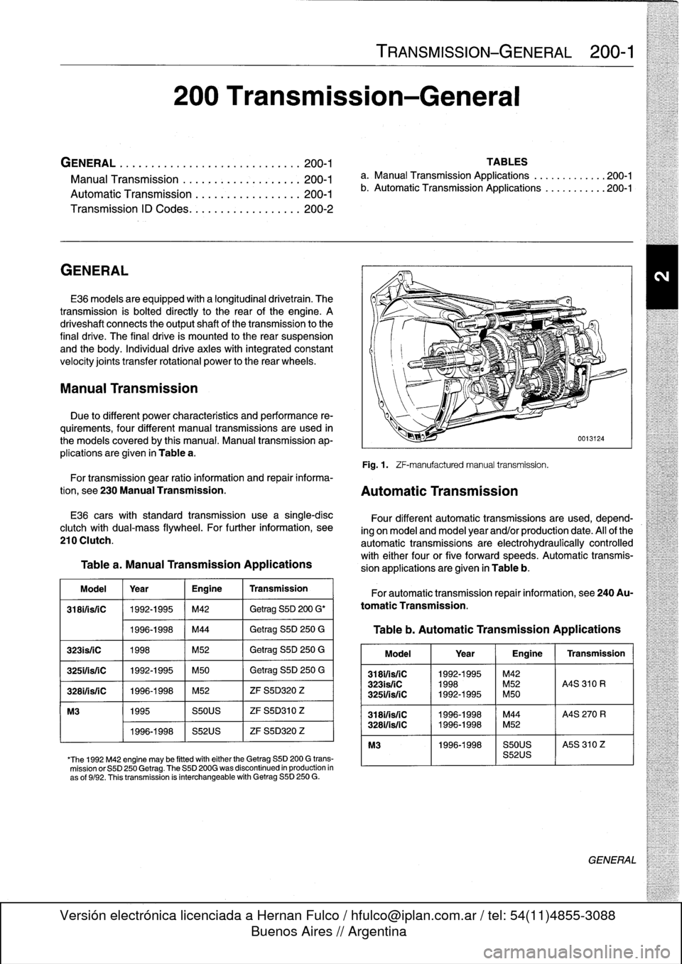
Fig
.
1
.
ZF-manufacturedmanual
transmission
.
For
transmission
gear
ratio
information
and
repair
informa-
tion,
see
230
Manual
Transmission
.
Automatic
Transmission
E36
carswith
standard
transmission
use
a
single-disc
clutch
with
dual-mass
flywheel
.
For
further
information,
see
210
Clutch
.
Table
a
.
Manual
Transmission
Applications
Model
Year
Engine
Transmission
318ifisfC
1992-1995
M42
Getrag
S5D
200
G'
1996-1998
M44
Getrag
S5D
250
G
323is/iC
1998
M52
Getrag
S5D
250
G
325ifsriC
1992-1995
M50
Getrag
S5D
250
G
3281/isfC
1996-1998
M52
ZF
S5D320
Z
M3
1995
S50US
ZF
S5D310
Z
1996-1998
S52US
ZF
S5D320
Z
'The
1992
M42
engine
may
be
fitted
witheither
the
Getrag
SSD
200
G
trans-
mission
or
S5D
250
Getrag
.
The
S5D
200G
was
discontinued
in
production
in
as
of
9/92
.
Thistransmission
is
interchangeable
with
Getrag
S5D
250
G
.
Four
different
automatic
transmissions
are
used,
depend-
ing
on
model
and
model
year
and/or
production
date
.
All
of
the
automatic
transmissions
are
electrohydraulically
controlled
with
either
four
or
five
forward
speeds
.
Automatic
transmis-
sion
applications
are
given
in
Table
b
.
For
automatic
transmission
repair
information,
see
240Au-
tomatic
Transmission
.
Table
b
.
Automatic
Transmission
Applications
Model
1
Year
1
Engine
1
Transmission
318i1is/1C
1992-1995
~
M42
323isfiC
1998
M52
A4S
310
R
3251/is/1C
1992-1995
M50
3181/isfC
11996-1998
M44
A4S
270
R
328i/is/1C
1996-1998
M52
M3
1996-1998
S50US
I
A5S
310
Z
S52US
GENERAL
Page 306 of 759
400-
4
BODY-GENERAL
INTERIOR
EQUIPMENT
E36
interiors
have
a
unique
character,
with
a
combínation
of
sporty
features
and
innovative
design
.
Al¡
body
versions
were
made
in
a
wide
choice
of
interior
and
exterior
colors
.
New
colors
with
matching
leather
and/or
fabric
upholstery
were
in-
troduced
for
each
model
year,
including
light-alloy
wheels
in
new
designs
.
Driving
comfort
is
enhanced
by
power
steering,
tilt
steering
wheel
(optional),
height-adjustable
front
seats,
and
electrical-
ly
adjustable
and
heated
rear-view
mirrors
.
Inside
thecar
there
are
reading
lights
at
four
seating
positions
.
Seats
and
Seat
Belts
NOTE-
Theseat
base
usedon
cars
with
pyrotechnic
seatbelt
Anatom¡cal
ly-correct
seats
are
constructed
from
polyure-
tensioners
is
not
interchangeable
with
the
earlier
seat
thane
foam
containing
areas
or
"zones"
of
different
firmness
.
base
.
The
seat
bases
have
steel
springs
for
added
support
and
strength
.
The
power
seats
are
provided
with
conveniently
lo-
Instruments
and
Controls
cated
switches
along
the
outside
edge
of
the
seat
.
Heated
seats
are
an
option
in
all
models
.
See
520
Seats
for
more
de-
Everything
in
the
interior
passenger
compartment
essential
tails
.
to
the
driver
is
logically
grouped
and
easy
to
reach
.
Al¡
instru-
ments
and
controls
havebeen
arranged
ergonomically
and
The
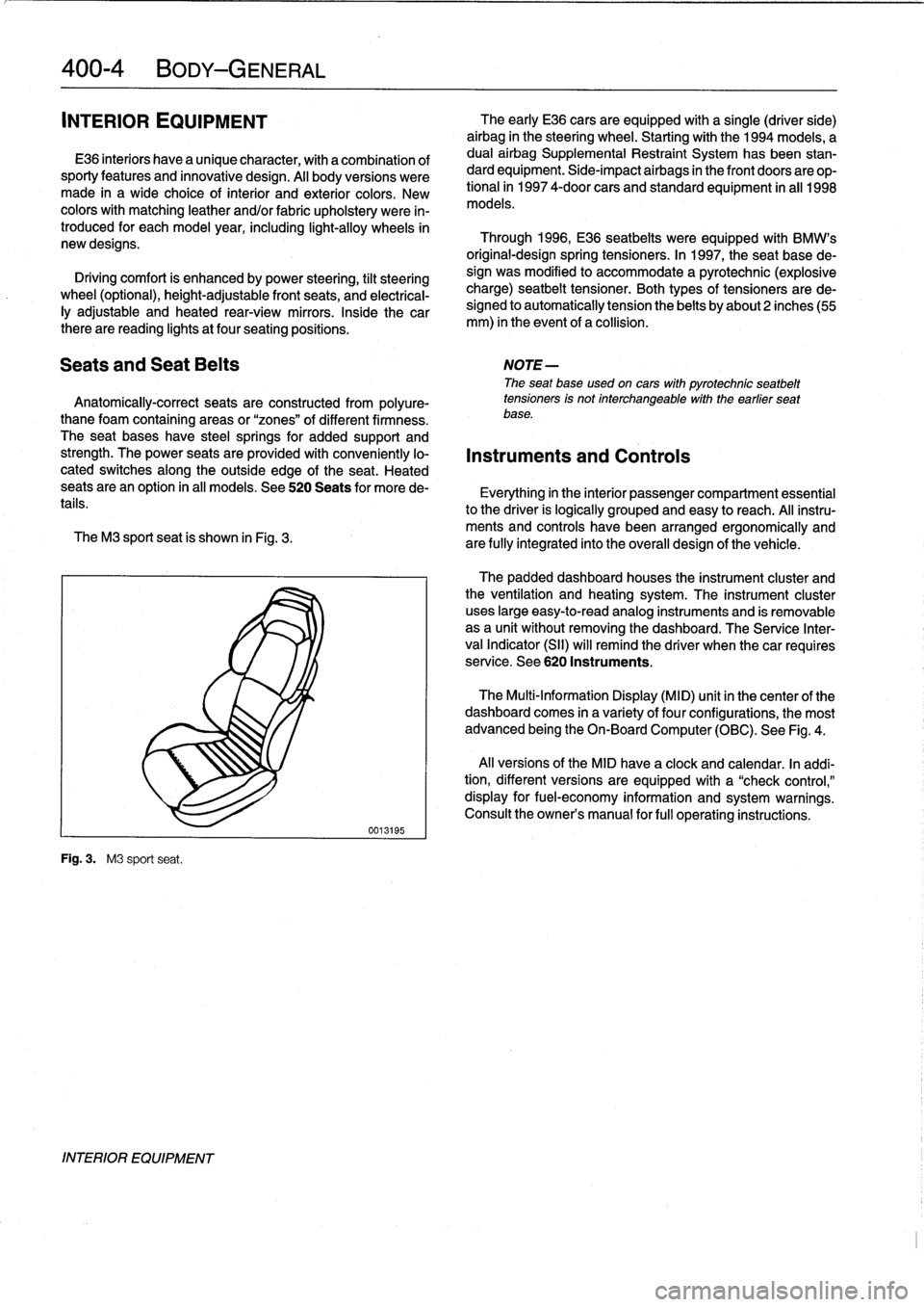
M3
sport
seat
is
shown
in
Fig
.
3
.
are
fully
integrated
into
the
overall
design
of
the
vehicle
.
Fig
.
3
.
M3
sport
seat
.
INTERIOR
EQUIPMENT
0013195
The
early
E36
cars
areequipped
with
a
single
(driver
side)
airbag
in
the
steering
wheel
.
Startingwith
the
1994
models,
a
dual
airbag
Supplemental
Restraint
System
has
been
stan-
dard
equipment
.
Side-impact
airbags
in
the
front
doors
are
op-
tional
in
1997
4-door
cars
and
standard
equipment
in
all
1998
models
.
Through
1996,
E36
seatbelts
were
equipped
with
BMW's
original-designspring
tensioners
.
In
1997,
the
seat
base
de-
sign
was
modified
to
accommodate
a
pyrotechnic
(explosive
charge)
seatbelt
tensioner
.
Both
types
of
tensioners
arede-
signed
to
automatically
tension
the
belts
by
about2
inches(55
mm)
in
the
event
of
a
collision
.
The
padded
dashboard
houses
the
instrument
cluster
and
the
ventilation
and
heating
system
.
The
instrument
cluster
uses
large
easy-to-read
analog
instruments
and
is
removable
as
a
unit
without
removing
the
dashboard
.
The
Service
Inter-
val
Indicator
(SII)
will
remind
the
driver
when
thecar
requires
service
.
See
620
Instruments
.
The
Multi-Information
Display
(MID)
unit
in
thecenter
of
the
dashboard
comes
in
a
variety
of
four
configurations,
the
most
advanced
being
the
On-Board
Computer
(OBC)
.
See
Fig
.
4
.
Al¡
versions
of
the
MID
have
a
clock
and
calendar
.
In
addi-
tion,
different
versions
areequipped
with
a
"check
control,"
display
for
fuel-economy
information
and
system
warnings
.
Consult
the
owner's
manual
for
fui¡
operating
instructions
.