steering rack BMW M3 1995 E36 Owner's Manual
[x] Cancel search | Manufacturer: BMW, Model Year: 1995, Model line: M3, Model: BMW M3 1995 E36Pages: 759
Page 271 of 759
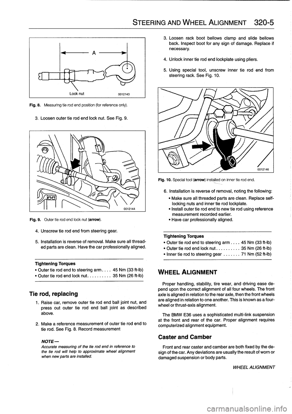
Fig
.
8
.
Measuring
tie
rod
end
position
(for
reference
only)
.
3
.
Loosen
outer
tie
rod
end
lock
nut
.
See
Fig
.
9
.
Lock
nut
4
.
Unscrew
tie
rod
end
from
steering
gear
.
0012143
"
Make
sure
all
threaded
parts
are
clean
.
Replace
self-
locking
nuts
and
inner
tie
rod
lockplate
.
"
Install
outer
tie
rod
end
to
new
tie
rod
using
reference
measurement
recorded
earlier
.
Fig
.
9
.
Outer
tie
rod
end
lock
nut
(arrow)
.
"
Have
car
professionally
aligned
.
5
.
Installation
is
reverse
of
removal
.
Make
sure
all
thread-
ed
parts
are
clean
.
Have
thecar
professionally
aligned
.
Tightening
Torques
"
Outer
tie
rod
end
losteering
arm
....
45
Nm
(33
ft-Ib)
"
Outer
tie
rod
end
lock
nut
..
.......
.
35
Nm
(26
ft-Ib)
Tie
rod,
replacing
1
.
Raise
car,
remove
outer
tie
rod
end
ball
jointnut,
and
press
out
outer
tie
rod
end
ball
joint
as
described
above
.
2
.
Make
a
reference
measurement
of
outer
tie
rod
end
to
tie
rod
.
See
Fig
.
8
.
Record
measurement
NOTE-
Accurate
measuring
of
the
tía
rod
end
in
reference
to
the
tie
rod
will
help
to
approximate
wheel
alignment
when
new
parts
are
installed
.
STEERING
AND
WHEEL
ALIGNMENT
320-
5
3
.
Loosen
rack
boot
bellows
clamp
and
slide
bellows
back
.
Inspect
boot
for
any
signof
damage
.
Replace
if
necessary
.
4
.
Unlock
inner
tie
rod
end
lockplate
using
pliers
.
5
.
Using
special
tool,
unscrew
inner
tie
rod
end
from
steeringrack
.
See
Fig
.
10
.
WHEEL
ALIGNMENT
Caster
and
Camber
Fig
.
10
.
Special
tool
(arrow)
installed
on
inner
tie
rod
end
.
6
.
Installation
is
reverse
of
removal,
noting
the
following
:
Tightening
Torques
"
Outer
tie
rod
end
to
steering
arm
..
.
.
45
Nm
(33
ft-Ib)
"
Outer
tie
rod
end
lock
nut
..........
35
Nm
(26
ft-Ib)
"
Inner
tie
rod
to
steering
gear
.......
71
Nm
(52
ft-Ib)
Proper
handling,
stability,
tire
wear,
and
driving
ease
de-
pendupon
the
correct
alignment
of
al¡
four
wheels
.
The
front
axle
is
aligned
in
relation
to
the
rear
axie,
then
the
front
wheels
are
aligned
in
relation
to
one
another
.
This
is
known
as
a
four-
wheel
or
thrust-axis
alignment
.
The
BMW
E36
uses
a
sophisticated
multi-link
suspension
at
the
front
and
rear
of
the
car
.
Proper
alignment
requires
computerized
alignment
equipment
.
Front
and
rear
caster
and
Camber
are
both
fixed
by
the
de-
sign
of
the
car
.
Any
deviations
are
usually
the
result
of
worn
or
damaged
suspension
or
body
parts
.
WHEEL
ALIGNMENT
Page 297 of 759
Brake
rotor,
removing
and
installing
Brake
rotors
shouldalways
be
replaced
in
pairs
.
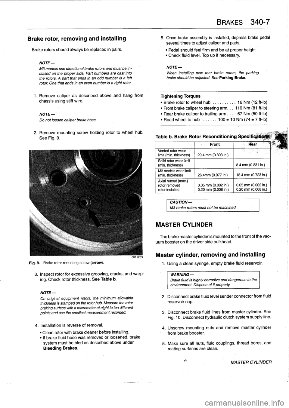
Fig
.
9
.
Brake
rotor
mounting
screw
(arrow)
.
3
.
Inspect
rotor
for
excessive
grooving,
cracks,
and
warp-
ing
.
Check
rotor
thickness
.
See
Table
b
.
4
.
Installation
is
reverse
of
removal
.
"
Clean
rotor
with
brakecleaner
before
installing
.
"
If
brake
fluid
hose
veas
removed
or
loosened,
brake
systemmustbe
bled
as
described
aboveunder
Bleeding
Brakes
.
BRAKES
340-
7
5
.
Once
brake
assembly
is
instalind,
depress
brakepedal
several
times
to
adjust
caliper
and
pads
.
"
Pedal
should
feel
firm
and
be
at
proper
height
.
"
Check
fluid
leve¡
.
Top
up
if
necessary
.
NOTE-
M3
models
use
directional
brake
rotors
and
mustbe
in-
NOTE-
stalled
on
the
proper
side
.
Part
numbes
are
cast
finto
When
installing
new
rear
brake
rotors,
the
parking
therotors
.
A
part
that
ends
in
an
odd
number
is
a
left
brakeshouldbe
adjusted
.
See
Parking
Brake
.
rotor
.
One
that
ends
in
an
even
number
is
a
right
rotor
.
1.
Remove
caliper
as
described-above
and
hang
from
Tightening
Torques
chassis
using
stiff
wire
.
"
Brake
rotor
to
wheel
hub
..........
16
Nm
(12
ft-Ib)
"
Front
brake
caliper
to
steering
arm
...
110
Nm
(81
ft-Ib)
NOTE-
"
Rear
brake
caliper
to
traíling
arm
....
67
Nm
(50
ft-Ib)
Do
notloosen
caliper
brake
hose
.
"
Road
wheel
to
hub
...
..
.
100
±
10
Nm
(74
t
7
ft-Ib)
2
.
Remove
mountingscrew
holding
rotor
to
wheel
hub
.
,
See
Fig
.
9
.
Table
b
.
Brake
Rotor
Reconditioning
Specificati*M`
Front
Rear
Vented
rotor
wear
limit
(min
.
thickness)
20
.4
mm
(0
.803
in.)
Solid
rotor
wear
limit
(min
.
thickness)
8
.4
mm
(0.331
in
.)
M3
models
wear
limit
(min
.
thickness)
26
.4mm
(0
.977
in
.)
18
.4
mm
(0
.723
in
.)
Axial
runout
(max
.)
rotor
removed
0
.05
mm
(0
.002
in
.)
0
.05
mm
(0
.002
in
.)
rotor
installed
0
.20
mm
(0
.008
in
.)
0
.20
mm
(0
.008
in
.)
CAUTION-
M3
brake
rotors
must
not
be
machined
.
MASTER
CYLINDER
The
brake
master
cylinder
is
mounted
to
the
front
of
the
vac-
uum
booster
on
the
driver
side
bulkhead
.
Master
cylinder,
removing
and
installing
1
.
Using
a
clean
syringe,
empty
brake
fluid
reservoir
.
WARNING
-
Brake
fluid
is
highly
corrosive
and
dangerous
to
the
environment
.
Dispose
of
it
properly
.
NOTE-
On
original
equipment
rotors,
the
mínimum
allowable
2
.
Disconnect
brake
fluid
leve¡
sender
connector
from
fluid
thickness
is
stamped
on
the
rotor
hub
.
Measure
the
rotor
reservoi
r
cap
.
brakingsurface
with
a
micrometer
at
eight
to
ten
different
points
and
use
the
smallest
measurement
recorded
.
3
.
Disconnect
brake
fluid
lines
frommaster
cylinder
.
See
Fig
.
10
.
Disconnect
hydraulic
clutch
system
supply
line
.
4
.
Unscrew
mounting
nuts
and
remove
master
cylinder
from
brake
booster
.
5
.
Make
sure
all
nuts,
fluid
couplings,
thread
bores,
and
mating
surfaces
are
clean
.
MASTER
CYLINDER
Page 358 of 759
515-10
CENTRAL
LOCKING
AND
ANTI-THEFT
EWS
II
control
module,
replacing
1
.
Disconnect
negative
(-)
cable
from
battery
.
CAUTION-
Prior
to
disconnecting
the
battery,
read
the
battery
disconnection
cautions
given
at
the
front
of
this
manual
onpage
vüf
.
2
.
Remove
glove
compartment
as
described
in
513
Inte-
rior
Trim
.
3
.
Remove
EWS
II
control
module
harness
connector
.
Pull
module
out
of
bracket
.
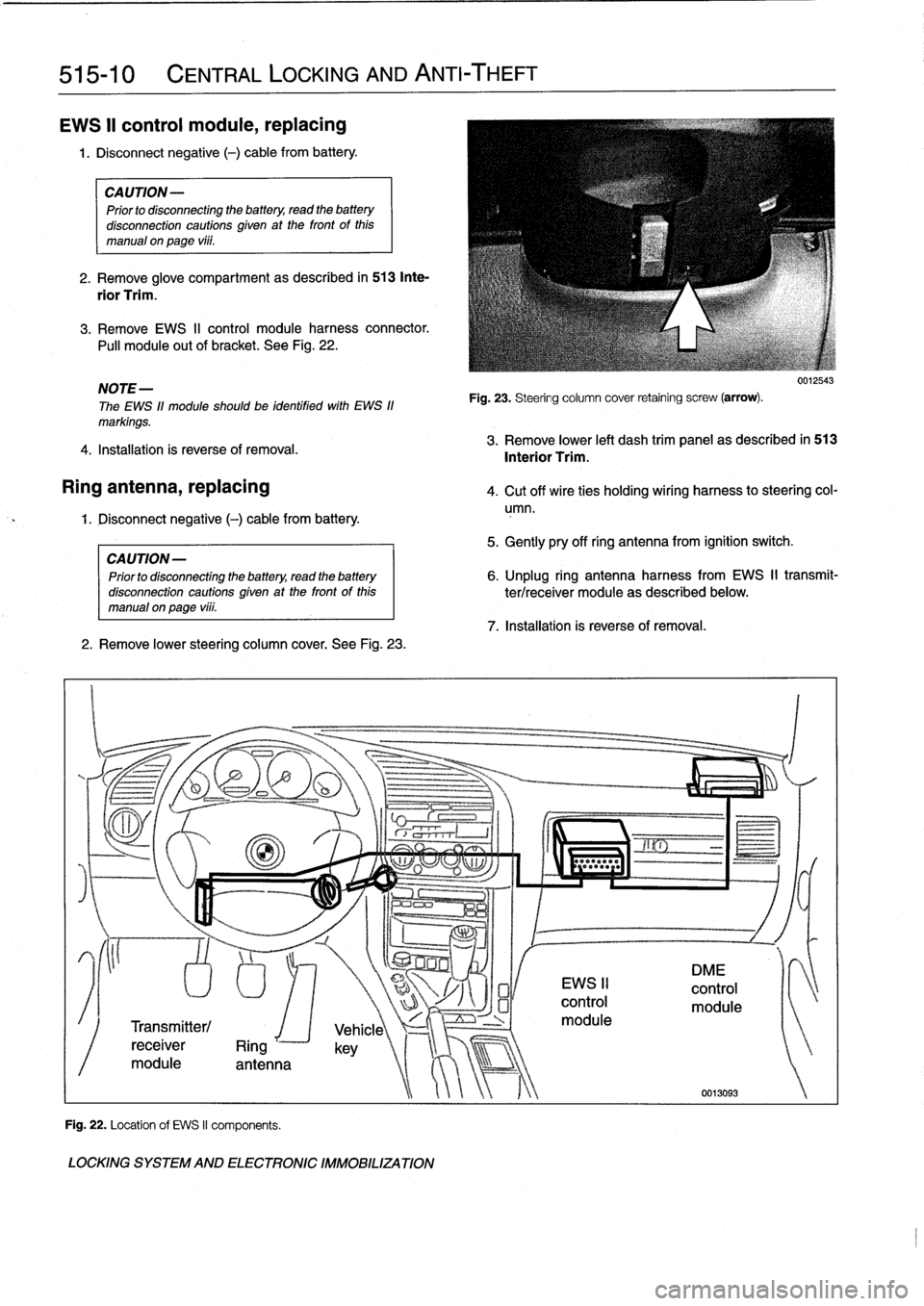
See
Fig
.
22
.
NOTE-
The
EWS
11
module
should
be
identified
with
EWS
11
markings
.
4
.
Installation
is
reverse
of
removal
.
Ring
antenna,
replacing
4
.
Cut
off
wire
ties
holding
wiring
harness
to
steering
col-
umn
.
1
.
Disconnect
negative
(-)
cable
from
battery
.
CAUTION
-
Prior
to
disconnecting
the
battery,
read
the
battery
disconnectioncautionsgiven
at
the
front
of
this
manualonpage
viii
.
2
.
Remove
lower
steering
column
cover
.
See
Fig
.
23
.
Transmitter/
receiver
Ring
r
module
antenna
Fig
.
22
.
Location
of
EWS
II
components
.
LOCKING
SYSTEM
AND
ELECTRONIC
IMMOBILIZATION
Fig
.
23
.
Steering
column
cover
retaining
screw
(arrow)
.
5
.
Gently
pry
off
ring
antenna
from
ignition
switch
.
7
.
Installation
is
reverse
of
removal
.
0012543
3
.
Remove
lower
left
dash
trim
panel
as
described
in
513
Interior
Trim
.
6
.
Unplug
ring
antennaharness
from
EWS
II
transmit-
ter/receiver
module
as
described
below
.
Page 397 of 759
Table
a
.
E36
Component
Locations
Component
Model
Year
Location
Refer
to
Anti-theft
Control
Module
1992-1998
Behind
glove
compartment
Fig
.
8
.
Fig
.
9
.
Anti-theft
Horn
1
1992-1998
1
Right
rear
engine
compartment
Anti-slip
(Traction)
Control
Module
1994-1998
Power
distribution
box
Fig
.
8
.
(AST/ASC+T)
Fig
.
9
.
Anti-slip
(Traction)
Control
Switch
1994-1998
In
center
console
Automatic
Climate
(A/C)
Control
1992-1998
Behind
center
console
Module
AutomaticTransmission
Range
1992-1998
~
Next
to
gear
shift
lever
in
center
console
Fig
.
29
.
Switch
(Gear
Position/Neutral
Safety
Switch)
Auxiliary
Cooling
Fan
Dual
Switch
1992-1998
Right
side
radiator
1
Fig
.
18
.
Auxiliary
Cooling
Fan
Motor
1992-1998
Behind
front
grill
Auxiliary
Fuse
Box
(Left
Splice
1992-1998
I
Behind
left
front
footwell
kick-panel
Panel)
Auxiliary
RelayPanel
1
1992-1998
1
Left
side
of
dash
under
steering
column
Auxiliary
Fuse
Box
In
Trunk
1
1997-1998
1
Right
sideof
trunk
behind
trim
panel
AuADSry
ThrottlePosition
Motor
11994-1998
Front
of
engine
compartment
B+
Jump
Start
Junction
Point
1992-1998
Right
rear
of
engine
compartment
Fig
.
7
.
Back-Up
Light
Switch
(Manual)
1992-1998
Right
or
left
side
top
of
transmission
Fig
.
30
.
Body
Electronics
Control
Module
1994-1998
Behindglove
compartment
Fig
.
8
.
(ZKE
IV)
Fig
.
9
.
Brake
Fluid
Level
Sensor
1992-1998
Top
of
brake
fluid
reservoir
at
master
cylinder
Fig
.
15
.
Brake
Light
Switch
1
1992-1998
1
On
brake
pedal
supportbracket
Brake
Pad
Sensor,
Left
Front
1
1992-1998
1
Left
front
brake
caliper
Brake
Pad
Sensor,
Right
Rear
1992-1998
Right
rear
brake
caliper
Camshaft
Actuator
(VANOS)
1993-1998
Front
of
cylinder
head
Camshaft
Position
Sensor
(Cylinder
1992-1998
Front
of
engine
Identification)
Carbon
Canister
Valve
(TLEV)
1
1997-1998
1
In
sparewheel
well
in
trunk
ELECTRICAL
COMPONENT
LOCATIONS
610-11
Fig
.
5
.
Fig
.
4
.
Fig
.
24
.
Fig
.
7
.
Central
Locking
Module
(ZVM)
11992-1993
1
Behindglove
compartment
I
Fig
.
8
.
Fig
.
9
.
Check
Control
Module
(if
applicable)
1
1992
-
1998
1
Below
left
side
of
dash
Child
Protection
Window
Control
1992-1998
Center
console
(console)
Chime
Module
1992-1998
Below
left
side
of
dash
inleft
dash
trim
panel
Clock
(Multi-Function)
1993-1998
Center
console
Clutch
Pedal
Switch
1992-1998
On
clutch
pedal
support
bracket
Continued
COMPONENT
LOCATIONS
Page 453 of 759
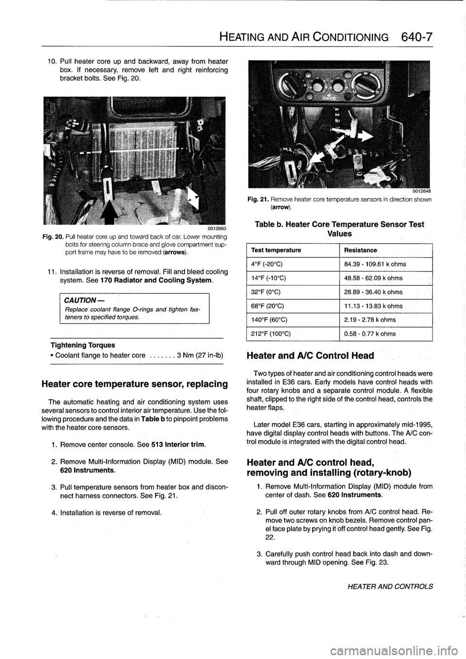
10
.
Pul¡
heater
core
up
and
backward,
away
from
heater
box
.
If
necessary,
remove
left
and
right
reinforcing
bracket
bolts
.
See
Fig
.
20
.
CAUTION-
Replace
coolant
flange
O-rings
and
tighten
fas-
teners
to
specified
torques
.
Tightening
Torques
1
.
Remove
center
console
.
See
513
Interior
trim
.
0012660
Fig
.
20
.
PA
heater
core
upand
towardback
of
car
.
Lower
mounting
bolts
for
steering
column
brace
and
glove
compartment
sup-
port
frame
may
have
to
be
removed
(arrows)
.
11
.
Installation
is
reverse
of
removal
.
Fill
and
bleed
cooling
system
.
See
170
Radiator
and
Cooling
System
.
"
Coolant
flange
to
heater
core
.
..
....
3
Nm
(27
in-lb)
Heater
andA/C
Control
Head
Heatercore
temperature
sensor,
replacing
The
automatic
heating
and
air
conditioning
systemuses
severa¡
sensors
to
control
interior
air
temperature
.
Use
the
fol-
lowing
procedure
and
the
data
in
Table
b
to
pinpoint
problems
with
theheater
core
sensors
.
2
.
Remove
Multi-Information
Display
(MID)
module
.
See
6201nstruments
.
HEATING
AND
AIR
CONDITIONING
640-7
0012648
Fig
.
21
.
Remove
heatercore
temperaturesensors
in
direction
shown
(arrow)
.
Table
b
.
Heater
CoreTemperatureSensor
Test
Values
Test
temperature
Resistance
4°F
(-20°C)
84
.39
-
109
.61
k
ohms
14
°
F
(-10°C)
48
.58
-
62
.09
k
ohms
32°F
(0°C)
28
.89
-
36
.40
k
ohms
68°F
(20°C)
11
.13
-
13
.83
k
ohms
140°F
(60°C)
2
.19
-
2
.78
k
ohms
212°F
(100°C)
0
.58
-
0
.77
k
ohms
Two
types
of
heater
and
aír
conditioning
control
heads
viere
installed
in
E36
cars
.
Early
models
have
control
heads
with
four
rotary
knobs
and
a
separate
control
module
.
A
flexible
shaft,
clipped
to
the
right
sideof
the
control
head,
controls
the
heater
flaps
.
Later
model
E36
cars,
starting
in
approximately
mid-1995,
have
digital
display
control
heads
with
buttons
.
The
A/C
con-
trol
module
is
integrated
with
the
digital
control
head
.
Heater
and
A/C
control
head,
removing
and
installing
(rotary-knob)
3
.
Pul¡
temperature
sensors
from
heater
box
and
discon-
1
.
Remove
Multi-Information
Display
(MID)
module
from
nect
harness
connectors
.
See
Fig
.
21
.
center
of
dash
.
See
620
Instruments
.
4
.
Installation
is
reverse
of
removal
.
2
.
Pul¡
off
outer
rotary
knobs
from
A/C
control
head
.
Re-
move
two
screwsonknob
bezels
.
Remove
control
pan-
el
face
plate
by
prying
it
off
control
head
gently
.
See
Fig
.
22
.
3
.
Carefully
push
control
head
back
into
dash
and
down-
ward
through
MID
opening
.
See
Fig
.
23
.
HEATER
AND
CONTROLS
Page 757 of 759
8
INDEX
Speakers
See
Radio
SRS
(Supplemental
restraint
system)
See
Airbag
system
(SRS)
Starter
See
Battery,
starter,
alternator
Steering
and
wheel
alignment
general
information
320-1
caster
and
camber
320-5
front
toe-in
and
toe
difference
angle
320-6
outer
tie
rod
end,
replacing
320-4
power
steering
pump,
removing/
installing
320-2
power
steering
system
320-2
power
steering
system,
bleeding/filling
320-3
rear
toe-in
320-6
steering
gear320-3
steering
gear
rack,
removing/installing
320-3
steering
wheel
320-1
steering
wheel,
removing/installing
320-1
tie
rod,
replacing
320-5
wheel
alignment
320-5
wheel
alignment
specifications
320-6
Steering
gear
See
steering
and
wheel
alignment
Strut
See
Front
suspension
Subframe
See
Front
suspension
Sunroof
general
information
540-1
motor,
removing/installing
540-3
panel,
adjusting
540-2
panel,
emergency
closing
540-2
Suspension,
front
See
Front
suspension
Suspension,
rear
See
Rear
suspension
Suspension,
steering
and
brakes
general
information
300-1
al¡
season
traction
(AST)
300-4
antilock
brake
system
(ABS)
300-2
brakes
300-2
front
suspension
300-1
integrated
systems
300-2
M3
suspension
and
brakes
300-7
steering
300-2
rear
suspension
300-2suspension
and
steering
troubleshooting
300-7
tires
and
wheels300-2
T
Switches
and
electrical
accessories
general
information
612-1
dome
light,
rear
map
lights,
trunk
light,
replacing
bulbs
612-7
hazard
warning
switch,
replacing
612-5
headlight
switch,
replacing
612-5
foglight
switch,
replacing
612-5
ignition
electrical
switch,
replacing
612-3
ignition
lock
cylinder,
replacing
612-4
ignition
switch
assembly
612-3
outside
mirror
switch,
replacing
612-6
power
window
switch,
replacing
612-5
turn
signal
switch
and
wiper
switch,
removing/installing
612-1
wiper
switch
See
turn
signal
and
wiper
switch
Taillight
See
Exterior
lighting
Thermostat
See
Cooling
system
Throttleposition
sensor
(TPS)
See
Fuel
injection
Throw-out
bearing
See
ClutchTierod
See
Steering
and
wheel
alignment
Tires
See
Suspension,
steering
and
brakes-general
See
also
Maintenance
program
Timing
chain
See
Camshaft
timing
chain
Toe-in
See
Steering
and
wheel
alignment
Tools
See
Fundamentals
for
the
do-it-
yourself
owner
Torque
convector
See
Automatic
transmission
Towing
See
Fundamentals
for
the
do-it-
yourself
owner
Traction
control
See
also
Suspension,
steering
and
brakes-general
Trailing
arm
See
Rear
suspension
Transmission-general
See
also
Automatic
transmission
See
also
Manual
transmission
general
information
200-1
automatic
transmission
200-1
manual
transmission
200-1
transmission
ID
codes
200-2
Transmission
fluid
See
Maintenance
program
See
also
Automatic
transmission
Transmission
input
shaft
See
Manual
transmission
Transmission
output
shaft
See
Manual
transmission
Trim,
interior
See
Interior
trim
Trunk
lid
general
information
412-1
trunk
lid,
412-1
trunk
lid,
aligning
412-1
trunk
lid,
removing/installing
412-1
trunk
lid
support
strut,
removing/
installing
412-2
U
Upholstery
See
Maintenance
program
U-joints
See
Driveshaft
V
V-belt
See
Maintenance
program
Vacuum
booster
See
Brakes
Vacuum
leaks
See
Engine-general
Valveguides
See
Cylinder
head
and
valvetrain
Valve
seals
See
Cylinder
head
and
valvetrain
Valveseats
See
Cylinder
head
and
valvetrain
Valves
See
Cylinder
head
and
valvetrain
Valvetrain
See
Cylinder
head
and
valvetrain
VANOS
(variable
valve
timing)
See
Camshaft
timing
chaín
See
also
Engine-general
Vehicle
identification
number
(VIN)
See
Fundamentals
for
the
do-it-
yourself
owner
Vehicle
speed
sensor
See
Instruments
Ventilation
See
Air
conditioning
See
also
Heating
Voltage
regulator
See
Battery,
starter,
alternator
Voltage
tests
See
Electrical
system-general
W
Warnings
vi¡
Washer
fluid
pump
See
Wipers
and
washers
Washers
See
Wipers
and
washers
Water
pump
See
Cooling
system
Waxing
See
Maintenance
program