check engine BMW M3 1998 E36 Workshop Manual
[x] Cancel search | Manufacturer: BMW, Model Year: 1998, Model line: M3, Model: BMW M3 1998 E36Pages: 759
Page 423 of 759
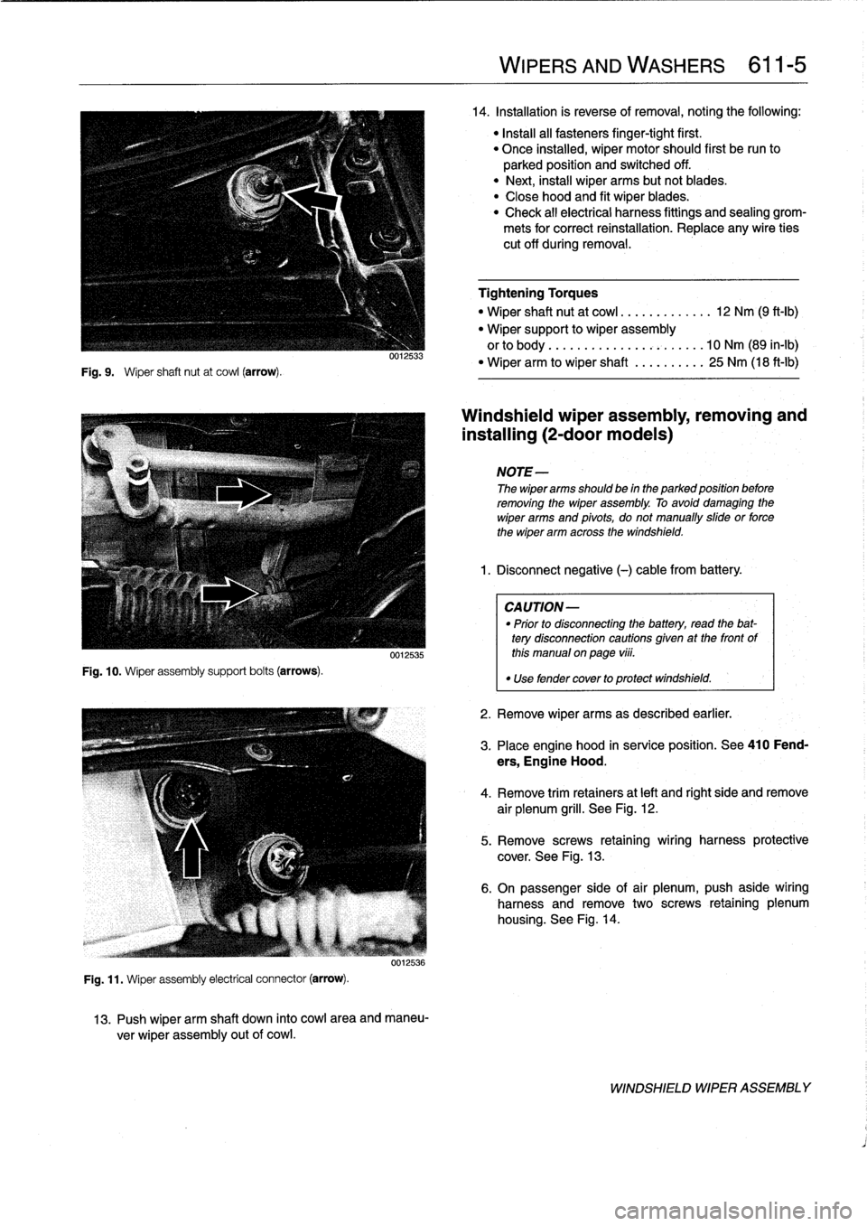
Fig
.
9
.
Wiper
shaft
nut
at
cowl
(arrow)
.
Fig
.
10
.
Wiper
assembly
support
bolts
(arrows)
.
0012533
0012535
Fig
.
11
.
Wiper
assembly
electrical
connector
(arrow)
.
0012536
13
.
Push
wiper
arm
shaft
down
into
cowl
area
and
maneu-
ver
wiper
assembly
out
of
cowl
.
WIPERS
AND
WASHERS
611-
5
14
.
Installation
is
reverse
of
removal,noting
the
following
:
"
Install
all
fasteners
finger-tight
first
.
"
Once
installed,
wiper
motor
should
first
be
run
to
parked
position
and
switched
off
.
"
Next,
instaf
wiper
arms
butnotblades
.
"
Close
hood
and
fit
wiper
blades
.
"
Check
all
electrical
harness
fittings
and
sealing
grom-
mets
for
correct
reinstallation
.
Replace
any
wire
ties
cut
off
during
removal
.
Tightening
Torques
"
Wiper
shaft
nut
at
cowl
.............
12
Nm
(9
ft-Ib)
"
Wiper
support
to
wiper
assembly
orto
body
..
..
..
.
...............
10
Nm
(89
in-lb)
"
Wiper
arm
to
wiper
shaft
..........
25
Nm
(18
ft-lb)
Windshieldwiper
assembly,
removing
and
installing
(2-door
modeis)
NOTE-
The
wiper
arms
should
be
in
the
parked
position
before
removing
the
wiper
assembly
.
To
avoid
damaging
the
wiper
arms
and
pivots,
donotmanually
sidde
or
force
the
wiper
arm
across
the
windshield
.
1
.
Disconnect
negative
(-)cablefrom
battery
.
CAUTION-
"
Prior
to
disconnectiog
the
battery,
read
the
bat-
tery
disconnection
cautionsgiven
at
the
front
of
this
manual
on
page
viii
.
"
Use
fendercover
to
protect
windshield
.
2
.
Remove
wiper
arms
as
described
earlier
.
3
.
Place
engine
hood
in
service
position
.
See410
Fend-
ers,
Engine
Hood
.
4
.
Remove
trim
retainers
at
left
and
right
side
and
remove
air
plenum
grill
.
See
Fig
.
12
.
5
.
Remove
screws
retaining
wiring
harness
protective
cover
.
See
Fig
.
13
.
6
.
On
passenger
side
of
air
plenum,push
aside
wiring
harness
and
remove
two
screws
retaining
plenum
housing
.
See
Fig
.
14
.
WINDSHIELD
WIPER
ASSEMBLY
Page 425 of 759
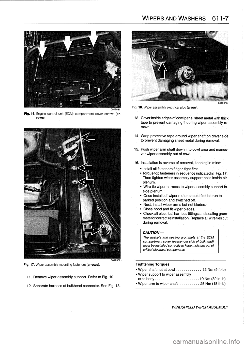
0012531Fig
.
16
.
Engine
control
unit
(ECM)
compartment
cover
screws
(ar-
rows)
.
WIPERS
AND
WASHERS
611-
7
Fig
.
18
.
Wiper
assembly
electrical
plug
(arrow)
.
uu1zbs6
13
.
Cover
inside
edges
of
cowi
panelsheet
metal
with
thick
tape
to
prevent
damaging
it
during
wiper
assembly
re-
moval
.
14
.
Wrap
protective
tape
around
wiper
shaft
on
driver
side
to
prevent
damaging
sheet
metal
during
removal
.
15
.
Push
wiper
arm
shaft
down
into
cowiarea
and
maneu-
ver
wiper
assembly
outof
cowi
.
16
.
Installation
is
reverse
of
removal,
keeping
in
mind
:
"
Install
all
fasteners
finger
tight
first
.
"
Torque
topfasteners
in
sequence
indicated
in
Fig
.
17
.
Then
tighten
wiper
assembly
support
bolts
inside
air
plenum
.
"
Wire
tie
wiper
harness
lo
wiper
assembly
support
in-
side
plenum
.
"
Once
installed
;
wiper
motor
should
first
be
run
to
parked
position
and
switched
off
.
"
Next,
insta¡¡
wiper
arms
butnot
blades
.
"
Close
hood
and
fit
wiper
blades
:
"
Check
all
electrical
harness
fittings
and
sealing
grom-
mets
for
correct
reinstallation
.
Replace
al]
wire
ties
cut
during
removal
.
CAUTION-
The
gaskets
and
sealing
grommets
at
the
ECM
compartment
cover
(passenger
sideof
bulkhead)
must
be
installed
correctly
to
keep
moisture
out
of
critica¡
electrical
componente
.
Fig
.
17
.
Wiper
assembly
mounting
fasteners
(arrows)
.
Tightening
Torques
"
Wiper
shaft
nut
at
cowi
..
.
.
..
.......
12
Nm
(9
ft-Ib)
11
.
Remove
wiper
assembly
support
.
Refer
to
Fig
.
10
.
"
Wiper
support
to
wiper
assembly
or
to
body
.........
...
..........
10
Nm
(89
in-lb)
12
.
Separate
harness
at
bulkhead
connector
.
See
Fig
.
18
.
-
Wiper
arm
to
wiper
shaft
..........
25
Nm
(18
ft-Ib)
WINDSHIELD
WIPER
ASSEMBLY
Page 427 of 759
WINDSHIELD
CLEANING
SYSTEM
Washer
f
luid
reservoir,
replacing
1
.
Open
hood
and
siphon
out
washer
fluid
reservoir
.
The
windshieldcleaning
system
includes
the
spray
nozzles
in
the
engine
hood,
the
washer
fluid
pump,
and
the
washer
flu-
id
reservoir
in
the
front
passenger
side
of
the
engine
compart-
ment
.
The
windshield
spray
nozzles
can
be
aimed
by
using
asew-
ing
need1e
or
a
similar
diameter
stiff
piece
of
wire
.
Windshield
spray
nozzle,
removing
and
installing
1
.
Open
hood
andremove
hood
insulating
pad
retaining
clips
until
bottom
of
nozzle
canbe
fully
accessed
.
See
410
Fenders,
Engine
Hood
.
2
.
Carefully
disconnect
hose
from
nozzle
.
Disconnect
har-
ness
connectors
for
nozzleheater
.
3
.
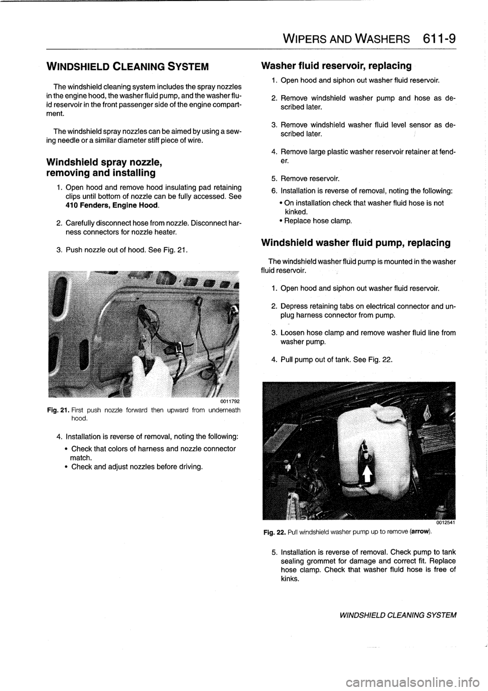
Push
nozzleout
of
hood
.
See
Fig
.
21
.
Fig
.
21
.
First
push
nozzle
forward
then
upward
from
underneath
hood
.
4
.
Installation
is
reverse
of
removal,
noting
the
following
:
"
Check
that
colors
of
harness
and
nozzle
connector
match
.
"
Check
and
adjust
nozzles
before
driving
.
WIPERSAND
WASHERS
611-
9
2
.
Remove
windshield
washer
pump
and
hose
as
de-
scribed
later
.
3
.
Remove
windshield
washer
fluid
level
sensor
as
de-
scribed
later
.
4
.
Remove
large
plastic
washer
reservoir
retainer
at
fend-
e
r
.
5
.
Remove
reservoir
.
6
.
Installation
is
reverse
of
removal,
noting
the
following
:
"
On
installation
check
that
washer
fluid
hose
is
not
kinked
.
"
Replacehose
clamp
.
Windshield
washer
fluid
pump,
replacing
The
windshield
washer
fluid
pump
ís
mounted
in
the
washer
fluid
reservoir
.
1
.
Open
hood
and
siphon
out
washer
fluid
reservoir
.
2
.
Depress
retaining
tabs
on
electrical
connector
and
un-
plug
harness
connector
from
pump
.
3
.
Loosen
hose
clamp
and
remove
washer
fluidline
from
washer
pump
.
4
.
PA
pump
out
of
tank
.
See
Fig
.
22
.
Fig
.
22
.
Pull
windshield
washer
pump
up
to
remove
(arrow)
.
5
.
Installation
is
reverse
of
removal
.
Check
pump
to
tank
sealing
grommet
for
damage
and
correct
fit
.
Replace
hose
clamp
.
Check
that
washer
fluid
hose
is
free
of
kinks
.
WINDSHIELD
CLEANING
SYSTEM
Page 438 of 759
620-2
INSTRUMENTS
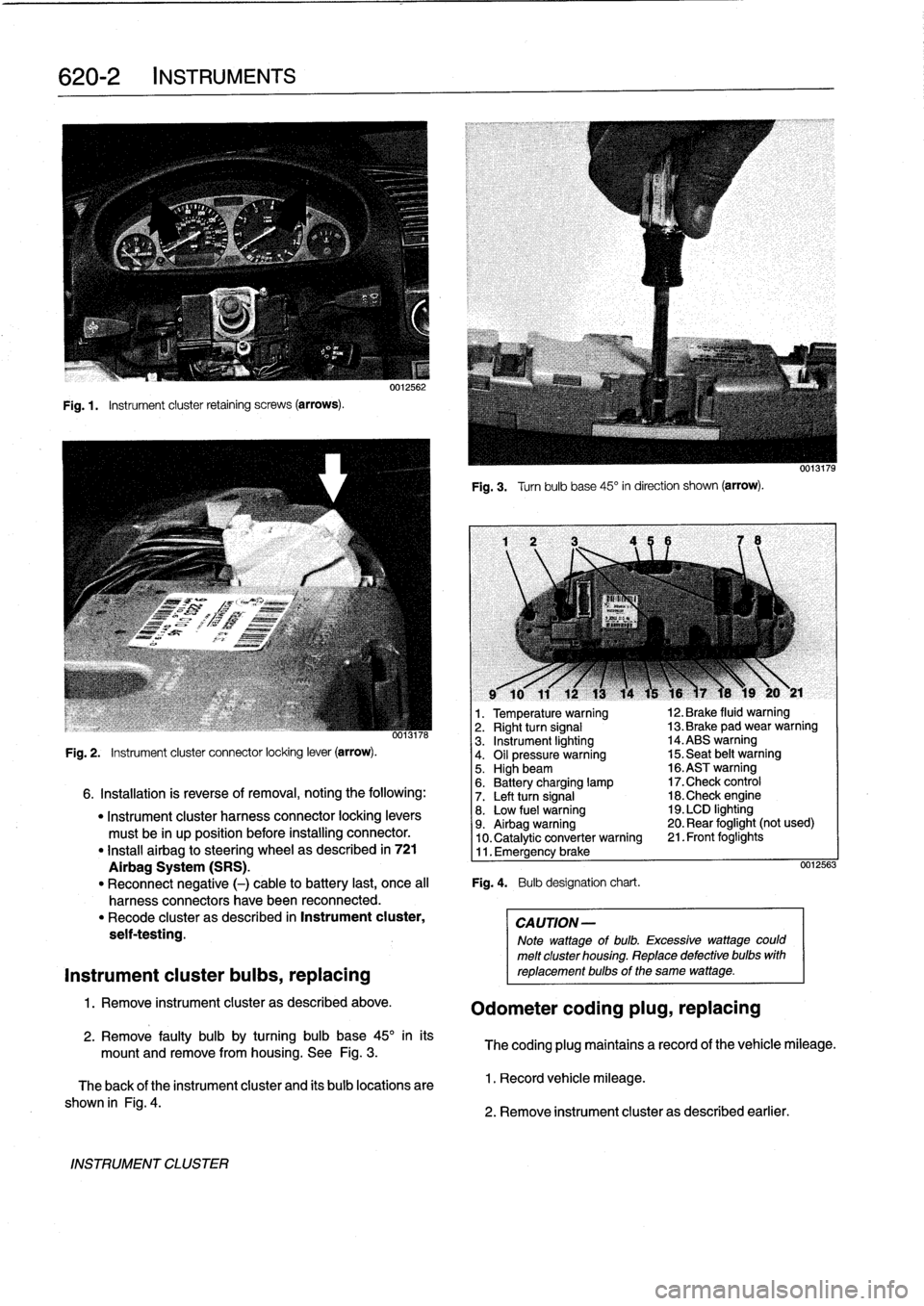
Fig
.1.
Instrument
cluster
retaining
screws
(arrows)
.
INSTRUMENT
CLUSTER
0012562
Fig
.
3
.
Turnbulb
base
45°
in
direction
shown
(arrow)
.
l
v
w
r
v
9
10
11
12
13
14
15
16
)7
18
19
20
y
21
1
.
Temperature
warning
12
.
Brake
fluid
warning
oo13n6
2
.
Right
turn
signal
13
.
Brake
pad
wear
warning
3
.
Instrument
lighting
14
.ABS
warning
Fig
.
2
.
Instrument
cluster
connector
locking
lever
(arrow)
.
4
.
Oil
pressure
warning
15
.
Seat
belt
warning5
.
Highbeam
16
.ASTwarning
6
.
Battery
charging
lamp
17
.Check
control
6
.
Installation
is
reverse
of
removal,
noting
the
following
:
7
.
Left
turn
signal
18
.Check
engine
"
Instrument
cluster
harness
connector
locking
levers
8
.
Low
fuel
warning
19
.
LCD
lighting
must
be
in
up
position
before
installing
connector
.
9
.
Airbag
warning
20
.
Rear
foglight
(not
used)
10
.
Catalytic
converter
warning
21
.
Front
foglights
"
Install
airbag
to
steering
wheel
as
described
in
721
11
.
Emergency
brake
Airbag
System
(SRS)
.
0012563
"
Reconnect
negative
(-)
cable
to
battery
last,
once
al¡
Fig
.
4
.
Bulb
designation
chart
.
harness
connectors
have
been
reconnected
.
"
Recode
cluster
as
described
in
Instrument
cluster,
CAUTION-
seif-testing
.
Note
wattage
of
bulb
.
Excessive
wattage
could
melt
cluster
housing
.
Replace
defective
bulbs
with
Instrument
cluster
bulbs,
replacing
reptacementbulbs
of
the
same
wattage
.
1
.
Remove
instrument
cluster
as
described
above
.
Odometer
coding
plug,
replacing
2
.
Remove
faulty
bulb
by
turning
bulb
base
45°
inits
mount
and
remove
from
housing
.
See
Fig
.
3
.
The
coding
plug
maintains
a
record
of
thevehicle
mileage
.
The
back
of
the
instrument
cluster
and
its
bulb
locations
are
1
.
Record
vehicle
mileage
.
shown
in
Fig
.
4
.
2
.
Remove
instrument
cluster
as
described
earlier
.
Page 441 of 759
FRONT
LIGHTING
.
...........
.
....
.
.
.
.
630-1
Headlight
buib,
replacing
............
.
.
.
.
630-1
Headlight
assembly,
removing
and
installing
.......
.
....
.
.
.
.
630-2
Foglight
assembly,
removing
and
installing
..
630-3
Front
turn
signal
assembly,
removing
and
installing
.....
.
.
.
........
630-4
GENERAL
The
headlight
and
foglight
assemblies
usehalogen
bulbs
.
To
ensure
the
longevity
of
halogen
bulbs,
the
bulb
glass
should
not
be
handied
.
Dirt
and
skin
oíls
may
cause
a
bulbto
fail
prematurely
.
If
necessarywipe
bulb
using
a
clean
cloth
dampened
with
rubbing
alcohol
.
NOTE-
Use
only
original
equipment
replacement
bulbs
.
Non-
original
equipment
bulbs
may
cause
false
failure
read-
ings
on
the
check
control
display
(where
applicable)
.
WARNING
-
INhenworking
on
electrical
systems,
remove
the
fuse
protecting
the
circuit
under
repair
.
See
610
Electrical
Component
Locations
.
FRONT
LIGHTING
Headlight
bulb,
replacing
1
.
Open
engine
hood
.
2
.
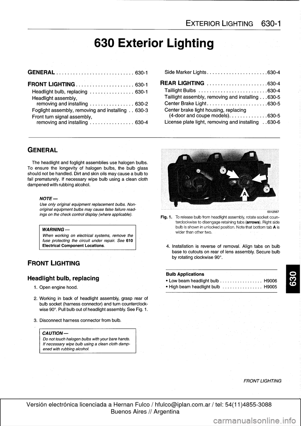
Working
in
back
of
headlight
assembly,grasp
rear
of
bulbsocket
(harnessconnector)
and
turn
counterclock-
wise
90°
.
Pull
bulb
out
of
headlight
assembly
.
See
Fig
.
1
.
3
.
Disconnect
harness
connector
from
bulb
.
CA
UTION-
Do
not
touch
halogen
bubs
with
yourbare
hands
.
If
necessary
wipe
bulb
using
a
clean
cloth
damp-
ened
with
rubbing
alcohol
.
630
Exterior
Lighting
EXTERIOR
LIGHTING
630-1
GENERAL
.
.
.
.
...
.
................
.
.
.
.
630-1
Side
Marker
Lights
.......
.
.
.
.
.
.......
.
..
630-4
REAR
LIGHTING
.
......
.
.
.
.
.
.
.
...
.
.
.
..
630-4
Taillight
Bulbs
..........
.
.
.
.
.
.....
.
.
.
.
.
630-4
Taillight
assembly,
removing
and
installing
.
.
.
630-5
CenterBrake
Light
.......
.
.
.
.
.
.
.
.
.
.
.
.
.
.
.
630-5
Center
brake
light
housing,
replacing
(4-door
and
coupe
models)
.
.
.
.
.......
.
.
.630-5
License
plate
light,
removingand
installing
.
.630-6
0012567
Fig
.1.
Torelease
bulbfrom
headlight
assembly,
rotate
socket
coun-
terclockwise
to
disengage
retaining
tabs
(arrows)
.
Right
side
bulb
is
shown
in
unlocked
position
.
Note
that
bottom
tab
A
is
wider
than
other
two
.
4
.
Installation
is
reverse
of
removal
.
Align
tabs
on
bulb
base
to
cutouts
on
rear
of
lens
assembly
.
Secure
bulb
by
rotating
clockwise
90°
.
Bulb
Applications
"
Low
beam
headlight
bulb
...
.
..
..
.........
H9006
"
High
beam
headlight
bulb
..
.
..
..
.........
H9005
FRONT
LIGHTING
Page 480 of 759
721-
4
AIRBAG
SYSTEM
(SRS)
CAUTION-
A
new
contact
ring
is
held
in
center
position
with
a
screw
.
This
locking
device
must
be
removed
after
contact
ring
is
installed
on
steering
wheel
.
See
Fig
.
4
.
Latercars
(1994
on)
:
"
Connect
ground
lead
at
contact
ring
.
"
When
installing
a
new
contact
ring
from
BMW,
remove
locking
pin
after
installing
contact
ring
to
steering
wheel
.
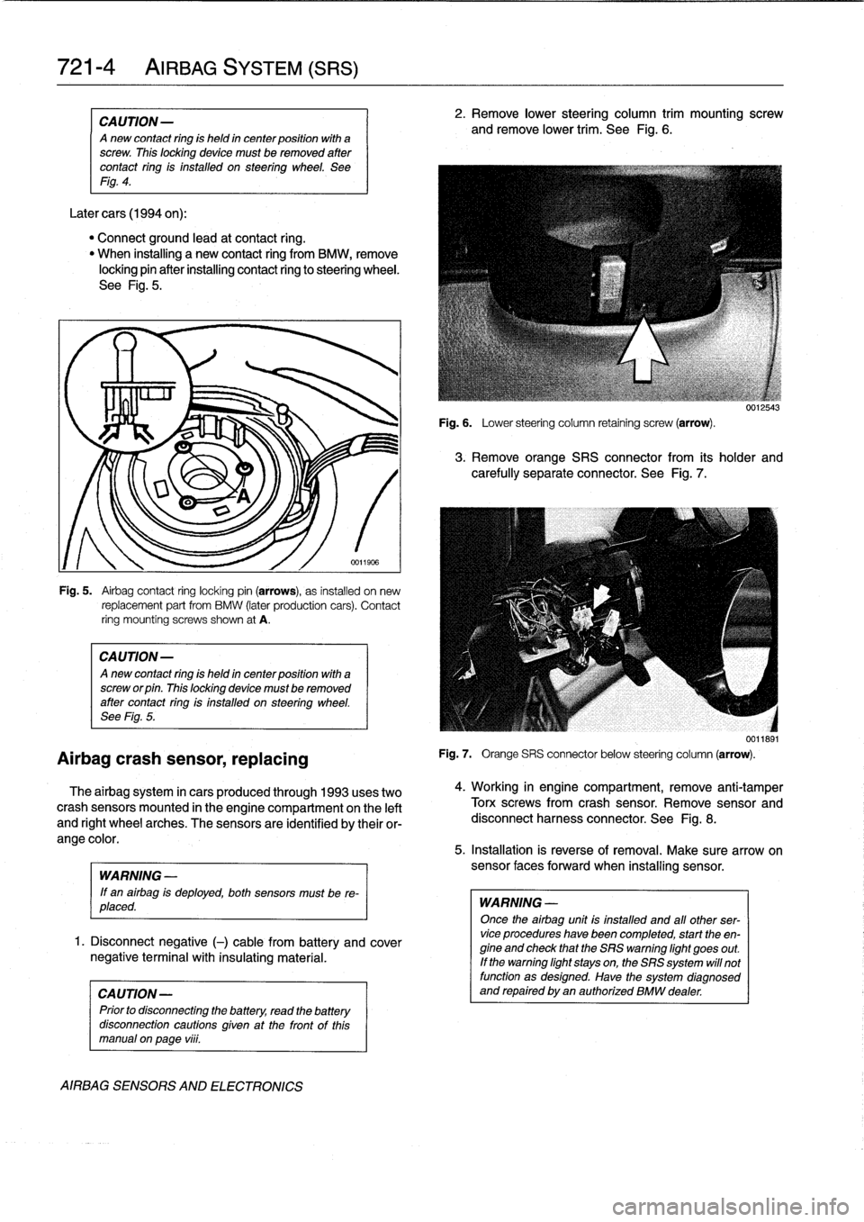
See
Fig
.
5
.
Airbag
crash
sensor,
replacing
Fig
.
5
.
Airbag
contact
ring
locking
pin
(arrows),
as
installed
on
new
replacement
part
from
BMW
(later
production
cars)
.
Contact
ring
mountíng
screws
shown
at
A
.
CAUTION-
Anew
contact
ring
is
held
in
center
position
with
a
screw
or
pin
.
This
locking
device
mustbe
removed
after
contact
ring
is
installed
on
steering
wheel
.
See
Fig
.
5
.
The
airbag
system
in
cars
produced
through
1993
uses
two
crash
sensors
mounted
in
the
engine
compartment
on
the
left
and
right
wheel
arches
.
The
sensors
are
identified
by
their
or-
ange
color
.
WARNING
-
If
en
airbag
is
deployed,
both
sensors
must
be
re-
placed
.
1
.
Disconnect
negative
(-)
cable
from
battery
and
cover
negative
terminal
with
insulating
material
.
CAUTION-
Prior
to
disconnectiog
the
battery,
read
the
battery
disconnection
cautíons
given
at
the
front
of
thls
manual
on
page
viii
.
AIRBAG
SENSORS
AND
ELECTRONICS
2
.
Remove
lower
steering
column
trim
mounting
screw
and
remove
lower
trim
.
See
Fig
.
6
.
Fig
.
6
.
Lower
steering
column
retaining
screw
(arrow)
.
3
.
Remove
orange
SRS
connector
from
its
holder
and
carefully
separate
connector
.
See
Fig
.
7
.
Fig
.
7
.
Orange
SRS
connector
below
steering
column
(arrow)
.
4
.
Working
in
engine
compartment,
remove
anti-tamper
Torx
screwsfrom
crash
sensor
.
Remove
sensor
and
disconnect
harness
connector
.
See
Fig
.
8
.
5
.
Installation
is
reverse
of
removal
.
Make
sure
arrow
on
sensor
faces
forward
when
installing
sensor
.
WARNING
-
Once
the
airbag
unit
is
installed
and
all
other
ser-vice
procedures
have
been
completed,
start
the
en-
gine
and
check
that
the
SRS
warning
light
goes
out
.
If
the
warning
light
stays
on,the
SRS
system
will
not
function
as
designed
.
Have
the
system
diagnosed
and
repaired
byen
authorized
BMW
dealer
.
0012543
0011891
Page 482 of 759
721-
6
AIRBAG
SYSTEM
(SRS)
5
.
Carefully
lift
airbag
unit
off
steering
wheel
and
discon-
6
.
Installation
is
reverse
of
removal
.
Tighten
right
side
nect
orange
harness
connector
from
rear
of
airbag
unit
.
screw
on
airbag
first
(as
viewedfrom
driver's
seat),
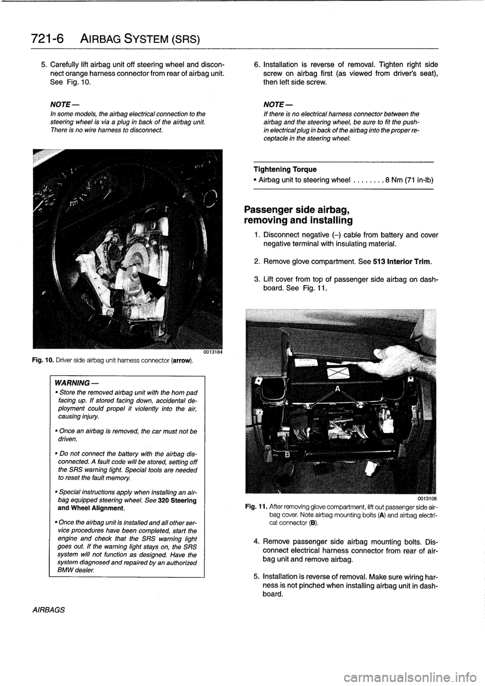
See
Fig
.
10
.
then
left
side
screw
.
NOTE-
NOTE-
In
some
models,
theairbag
electrical
connection
to
the
If
there
is
no
electrical
harness
connector
between
the
steering
wheel
isvia
aplug
in
back
of
the
airbag
unit
.
airbag
and
the
steering
wheel,
be
sure
to
fit
the
push
There
is
no
wire
harness
to
disconnect
.
in
electrical
plug
in
back
of
the
airbag
finto
the
proper
re-
ceptacle
in
the
steering
wheel
.
Fig
.
10
.
Driver
sideairbag
unit
harness
connector
(arrow)
.
AIRBAGS
WARNING
-
"
Store
the
removed
airbag
unit
with
the
horn
pad
facing
up
.
If
stored
facing
down,
accidental
de-
ployment
couldpropel
it
violently
into
the
air,
causing
injury
.
"
Once
an
airbag
is
removed,
the
car
must
not
be
driven
.
"
Do
not
connect
the
battery
with
the
airbag
dis-
connected
.
A
fault
code
will
be
stored,
setting
off
the
SRS
warning
light
.
Special
tools
are
needed
to
reset
the
fault
memory
.
"
Special
instructions
apply
when
installing
an
air-
bag
equipped
steering
wheel
.
See
320
Steering
and
Wheel
Alignment
.
"
Once
the
airbag
unit
is
installnd
and
all
other
ser-vice
procedureshave
been
completed,
start
the
engíne
and
check
that
the
SRS
warning
light
goes
out
.
If
the
warning
light
stays
on,
the
SRS
system
will
not
function
as
designed
.
Have
the
system
diagnosed
and
repaired
by
an
authorized
BMW
dealer
.
0013184
Tightening
Torque
"
Airbag
unitto
steering
wheel
........
8
Nm
(71
in-lb)
Passenger
side
airbag,
removing
and
installing
1
.
Disconnect
negative
(-)
cable
from
battery
and
cover
negative
terminal
with
insulating
material
.
2
.
Remove
glove
compartment
.
See
513
Interior
Trim
.
3
.
Lift
cover
from
topof
passenger
sideairbag
on
dash-
board
.
See
Fig
.
11
.
0013108
Fig
.
11
.
After
removing
glove
compartment,
lift
out
passenger
side
air-
bag
cover
.
Note
airbag
mounting
bolts
(A)
and
airbag
electri-
cal
connector
(B)
.
4
.
Remove
passenger
sideairbag
mounting
bolts
.
Dis-
connect
electrical
harness
connector
from
rear
of
air-
bag
unit
and
remove
airbag
.
5
.
Installation
is
reverse
of
removal
.
Make
sure
wiring
har-
ness
is
not
pínched
when
installing
airbag
unit
in
dash-board
.
Page 500 of 759
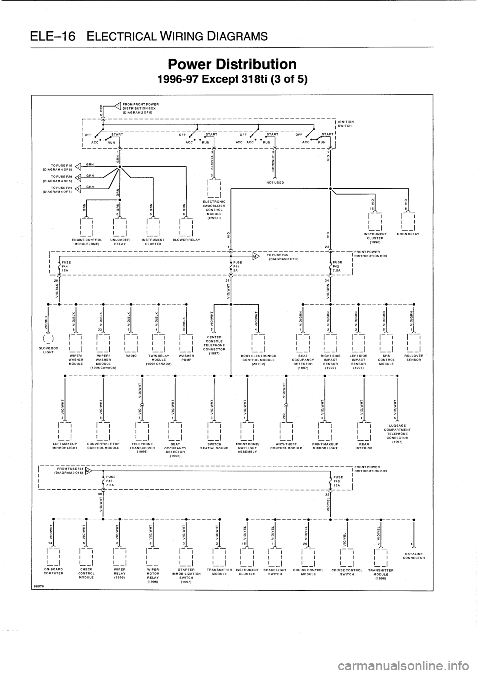
ELE-16
ELECTRICAL
WIRING
DIAGRAMS
88978
TO
FUSE
F16
yDIAGRAM
4
OF
5)
70FU
SEF28
K
GRN
(DIAGRAM
4OF5)
___
--------
_---------------------
______________
I
IGNITION
I
SWITCH
I
_
_
_-_-__-
-----------
I
OFF
START
OFF
START
OFF
START
F,
START
FROM
FRONT
POWER
r
<
DISTRIBUTION
BOX
(DIAGRAM
2OF5)
=OC---U-
-_-_---_-__-ACC--RU=
____CC_CC--R=N-
CC-PUN
Power
Distribution
1996-97
Except
318ti
(3
of
5)
ELECTRONICIMMOBLIZER
CONTROL
MODULE
(EWS11)
NOTUSED
2_
.
15
t
I
I
II
II
F-,
II
II
I
I
II
I
I
I
I
I
-I
L-1
INSTRUMENT
HORN
RELAY
ENGINECONTROL
UN
LOADER
INSTRUMENT
BLOWERRELAY
CLUSTER
No
DULE(DME)
RELAY
CLUSTER
°_
(1996)
-----
-------
1
1'
--
FRONTPOWER
I
M
TO
1111111
IDISDISTRIBUTION
BOX
(DIAGRAM
3
OF5)
II
FUSE
FUSE
USE
I
1'44
F43
42
I
!
'________________________________
5A
~
_________________
5=
el
231
51
41
51
51
41
1
J
1
2
J
1
2
J
1
5~
1),
1
I
.+
.
1
1
1
CE
.N+
TER
I
I
.+
.
i
I
.
1
I
.
1
I
.
1
1
1
1
1
I
I
II
II
I
I
I
I
CONSOLE
TELEPHONE
GLOVE
BOX
I
-
.
I
I
-
I
I
-)
I
-
I
I
-
I
CONNECTOR
LIGHT
(1987)
WIPER/
WIPER/
RADIO
TWIN
RELAY
WASHERWASHER
WASHER
MODULE
PUMPMODULE
MODULE
(1996
CANADA)
(1996
CANADA)
SEAT
RIGHTSIDE
LEFT
SIDE
SRS
ROLLOVER
OCCUPANCY
IMPACTIMPACT
CONTROLSENSOR
DETECTOR
SENSORSENSOR
MODULE
(1997)(1997)(1997)
O~
31
1~
~
1
31
11
51
I
I
I
I
I
I
I
I
I
I
I
I
I
I
I
I
I
I
LUG
AGE
I
I
II
II
I
I
II
I
I
II
II
I
I
COMPARTMENT
TELEPHONE
CONNECTOR
LEF7MAKEUP
CONVERTIBLETOP
TELEPHONE
SEAT
SWITCH
FRONTDOME/
ANTI-THEFT
RIGHTMAKEUP
REAR
(1997)
MI
PROFLIGHT
CONTROLMODULE
TRANSCEIVER
OCCUPANCY
SPATIALSOUND
MAPLIGHT
CONTROLMODULE
MIRROR
LIGHT
INTERIOR
(1996)
DETECTOR
ASSEMBLY
(199fi)
FROMFISE
141
---
(DIAGRAM
30F5)
M
________--_--_________________-_----------------
FRONTPOWER
DISTRIBUTIONBOX
(
FUSE
FUSE
1I
F45
F4fi
I
'S
7
.5A--______________-________________-______
___
30Y
32Y
I
i
F-
,I
iF-
,I
i
I
-
F
-
,
I-
ON-BOAR
CHECK
WIPER
WIPER
STARTER
TRANSMITTER
INSTRUMENT
BRAKELIGHT
CRUISECONTROL
CRUISECONTROL
TRANSMITTER
COMPUTER
CONTROL
RELAY
MOTOR
IMMOBILIZATION
MODULE
CLUSTER
SWITCH
MODULE
SWITCH
MODULE
MODULE
(1996)
RELAY
SWITCH
(1996)
(1998)
(1997)
0
TALINK
CONNECTOR
Page 505 of 759
TOFUSEF16
GGRN
(DIAGRAM
4
OF
5)
TOFUSEF28
HGRN
(DIAL
RAM
4
OF
5)
TOFUSEF24
GRN
(DIAGRAM
4
OF
5)
10437
2
F
-
1I
I
I
I
I
I
I
I
I
I
>
I
I
I
_I
L-1
L
I
D
I
_I
ENGINECONTROL
UNLOADER
INSTRUMENTUNCOUPLING
BLOWERNo
DULE(DME)
RELAY
CLUSTER
DIODE
RELAY
1
I
FUSE
I
F44
I
154
v__-----__---------
a--
_
---____--aaa-r
====
=---~,
.
I--1
I-
I
I,\
I
CONSOLE
I
I
_'
II
I
III
TELEPHONE
I1
GLOVEBOX
I
I
I
CONNECTOR
I
LIGHT
LEFT
RIGHT
SEAT
FIGHT
LEFT
ROLLOVER
SUPPLEMENTAL
FRONTFRONT
OCCUPANCY
SIDESIDE
SENSOR
RESTRAINT
SEATBELT
SEATBELTDETECTOR
IMPACTIMPACT
SYSTEM
SWITCH
SWITCH
SENSOR
SENSOR
CONTROL
MODULE
I
IGNITION
SWITCH
I
OFF
START
OFF
START
OFF
START
OFF
/
START
ACC-__U-
_____________
_
ACC
"
__U_
_____
AC
_-
_____
A
C
____
,
a
FROMFRONTPOWER
DISTRIBUTION
BOX
(DIAGRAM
2
OF
5)
56
ELECTRONICIMMOBLIZER
((
1
.
2
.8
L
(
L)
8
5O
1
8
~
CONTROL
9
MODULE
I
_
_
IF-")
I
1
I
I
I
I
I
I
WIPERI
RADIO
WASHER
BODYELECTRONICS
WASHER
Pump
CONTROL
MODULEMODULE
(ZKE
IV)
61
31
5'
I
I
I
I
I
I
I
II
I
I
I
I
I
I
I
LEFT
MAKEUP
CONVERTIBLETOP
TOP
SPATIAL
FRONTDOME/
ANTITHEFT
T
RIGHT
MAKEUP
LEFT
RIGHT
MIPROFLIGHT
CONTROLMODULEH
I
FI
SOUND
MAPLIGHT
CONTROLMODULE
MIRRORLIGHT
REAR
FEAR
SWTCH
RELAY
ASSEMBLY
INTERIOR
INTERIOR
______
-
-
-
-
-
_____________________________
-_
FRONTPOWER
FROMFUSE
F43
---
I
DISTRIBUTION
BOX
(OIAGRAM30F5)
J
II
FUSE
FUSE
I
F45
146
7
.5
-_
_
_
_
_
_
_
_
_
_
_
_
_
_
_
_
_
_
_
_
_
_
_
_
_
_
_
_
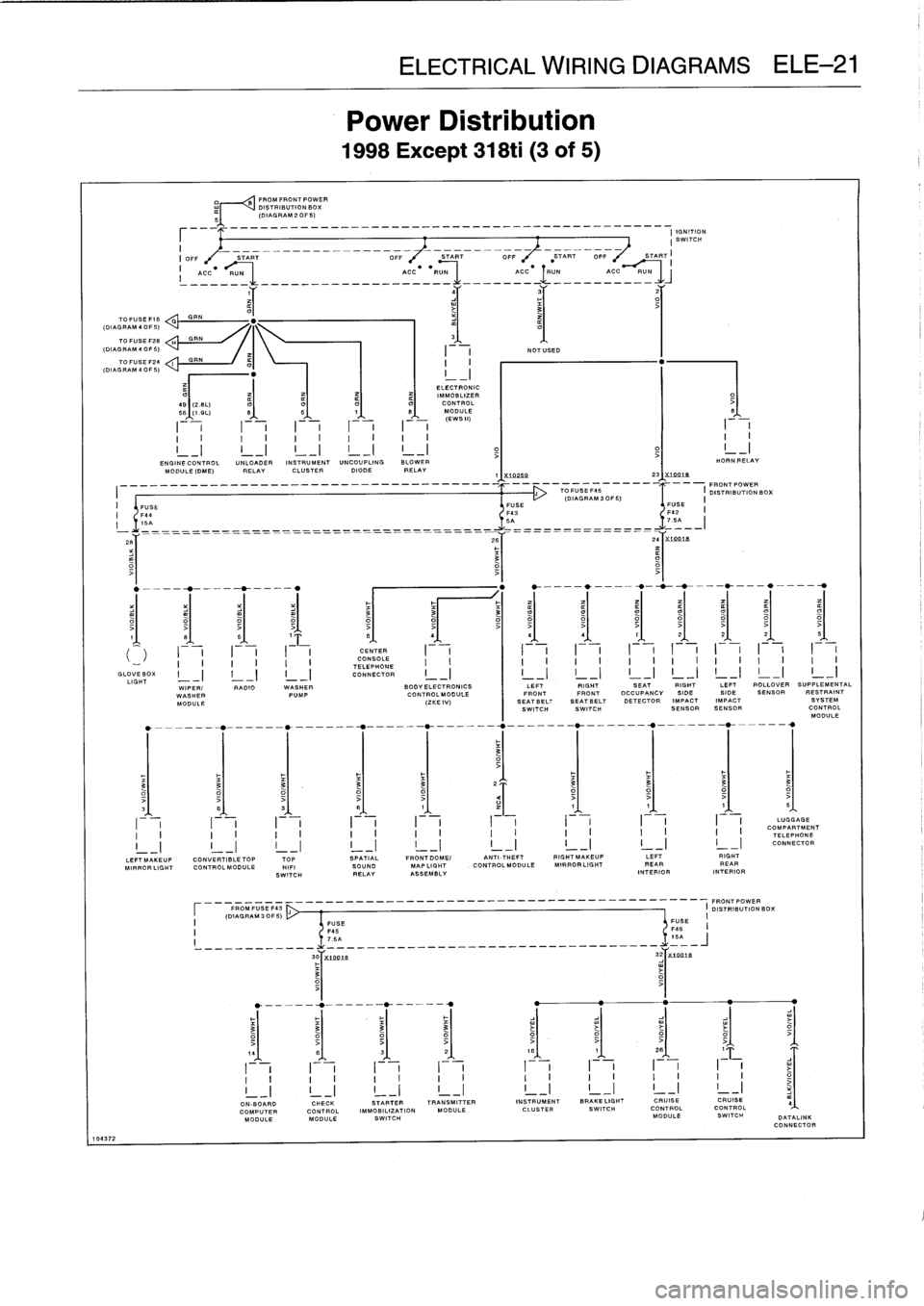
ELECTRICAL
WIRING
DIAGRAMS
ELE-21
Power
Distribution
1998Except
318ti
(3
of
5)
2B
NOTUSED
0259
231X
7Oat8
5I
4151
51
5
;
4
4
1
2
O
16
I
I
I
I
I
I
I
I
I
II
I
I
I
I
I
f
I
I
I
ON-BOARD
CHECK
STARTER
TRANSMITTER
INSTRUMENT
BRAKE
LISHT
COMPUTERCONTROL
IMMOBILIZATION
MODULE
CLUSTER
SWITCH
MODULE
MODULE
SWITCH
---
-
-
------
--
FRONT
POWER
TOFUSEF45
I
DISTRIBUTION
BOX
'DIAGRAM
S
CPS)
FUSE
"
FUSE
HORN
RELAY
CRUISECRUISE
CONTROLCONTROL
MODULE
SWITCH
I
I
I
I
I
II
I
I
I
I
I
I
I
I
I
I
I
I
I
I
I
I
I
I
I
I
II
II
II
LUGGAGECOMPARTMENT
II
II
II
TELEPHONE
CONNECTOR
DATALINK
CONNECTOR
Page 532 of 759
ELE-48
ELECTRICAL
WIRING
DIAGRAMS
TRANSMISSION
r
I
ENGINE
(HALL
CON
TROL
I
CONTROL
I_
(
I
EFFECT
I
(
MODULE
I
(
MODULE
I
(
CAMSHAFT
I
_____y
_
I
11"S)
1
--
j
(DIE)
I
(SENSOR
B'f
28
y_
1
..'r
BY
3ar
BET
26
~
3
8907
2
PASSENGERS
PASSENGERSPASSENGERS
PASSENGERS
SUPPRESSION
DRIVERS
DOOR
DRIVER
I
(DOOR
I
(
SEAT
I
(SEAT
I
I
SEATBACK
I
(
FILTER
I
(
WINDOW
I
(
LOCK
I
(
DOOR
I
(JAMB
I
(CONTROL
I
(HEATER
I
(HEATER
II
I
(MOTOR
I
(HEATER
I
(HANDLE
RIGHT
RIGHT
RIGHT
CD
I---
m
I
-
I_
i
II
REAR
REAR
REAR
CHANGER
(
INTERIOR
I
I
(
WINDOW
ml
I
(
INTERIOR
ml
I
I
1
G313
G302
(4
DOOR)
(1996)
ROLLOVER
CONVERTIBLE
CONVERTIBLECONVERTIBLE
CONVERTIBLE
WINDSCREEN
HIFI
RADIO
I
(
SENSOR
I
---
(
TOP
I
(
TOP
I
(
TOP-END
I
---
(
TOP
I
I
CoWLPANEL
I
(
AMPLIFIER
I
II
I
I
(
ACTUATING
I
I
OONTROL
I
(
POSITION
I
(
POSITION
I
(
LOCK
I
i
I
I
SWITCH
I
-(
MODULE
I
-(
SWITCH
I
,
---(
SWITCH
I
,-(
SWITCH
I
-I
1
-I
IGNITION
F---
CRANKSHAFT
I
(HOT
I
I
UNLOADER
1
'CYL1
IOYL3
COIL
POSITION
FILM
RELAY
IGNITIONIGNITION
I
I
(
AIR
I
(
(1997)
I
(
COIL
I
(
COILCOILSHIELD
_
SENSOR
SHIELD
MASS
METER
S
1
(
I
I
I
I
1
I
___
1
r
(
1996
)
.T
2T
21"
,
.-------
.
.W_-*---___--7-----__-41"
-
----___--0-f---_---7
1
.1
m
SEAT
CHECK
LEFT
ANTI-
RIGHT
DRIVERS
PASSENGERS
I
(
OCCUPANCY
I
(
CONTROL
I
(
REAR
I
(
THEFT
I
(
REAR
I
(
SEATBELT
I
(
SEAT
I
1
DETECTOR
I
(
MODULE
I
(
DOOR
I
(
CONTROL
I
(
DOOR
I
I
SWITCH
I
T
HEATER
1
_I
I
-I
L-1
CONTACT
I
-I
MODULE
I
-I
CONTACT
I
-I
I
_
I
SWITCH
I
PASSENGERS
9
I
'
DRIVERS
4
PASSENGERS
DRIVERS
1
PASSENGERS
1
4
DRIVERS
(
WINDOW
WINDOW
I
(
SIDE
I
(
SIDE
I
(
SEATBELT
I
(
SEA
2
T
I
I
MONITIORING
I
I
MONITIORING
I
(
IMPACT
I
(
IMPACT
I
(
SWITCH
I
(
HEATER
1
(
SWITCH
I-.(
SWITCH
I
V
I
SENSOR
I
v
I
SENSOR
I
5I
I
I
-(
-
(1997)
--
(1997)
--
(1997)
T
--
(1997)
SWITCH
-
Y
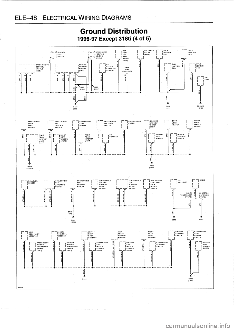
Ground
Distribution
1996-97
Except
318ti
(4
of
5)
i
997
__~
1996
m)
ONLYONLY
G123
GI9
GROUND
(318)
(318)
(318)
y
1
1
G203
G202
G202
(1996)
DATA
LINK
CONNECTOR
O
-___-___0_-t--__--_
.,---0__--_---`__
.,-_--_-_-*_--0
.-____-
CYL2
DYLa
I
I
IGNITION
I
I
IGNITION
I
I
m
COIL
l
I
I
COIL
1
'
o~
t
G302
(1996)
1
AIR
I
PUMP
31
3
aIaI¢~
W/HIFI
.
,I
W/STEREOTENSPEAKER6SPEAKER
SYSTEMSYSTEM