check engine BMW M3 1998 E36 Repair Manual
[x] Cancel search | Manufacturer: BMW, Model Year: 1998, Model line: M3, Model: BMW M3 1998 E36Pages: 759
Page 91 of 759
CYLINDER
HEAD
AND
VALVETRAIN,
RECONDITIONING
Thís
section
provides
the
specifications
and
special
recon-
ditioning
information
necessary
to
repair
the
cylinder
heads
covered
by
this
manual
.
If
machine
shop
services
are
not
readily
available,
one
al-
ternative
is
to
install
a
remanufactured
cylinder
head
froman
authorized
BMW
dealer
.
Cylinder
head
NOTE-
When
replacing
the
cylinder
headon
engines
with
re-
movablecamshaft
carriers,
be
sure
to
check
the
cam-
shaft
carrier
bearing
surfaces
for
warpage
.
4-cylinder
1
140
.0
mm
(5
.512
in)
1
139
.55
mm
(5
.494
in)
6-cylinder
1
140
.0
mm
(5
.512
in)
1
139
.7
mm
(5
.500
in)
CYLINDER
HEAD
AND
VALVETRAIN
116-
7
A
The
disassembled
cylinder
head
should
be
inspected
for
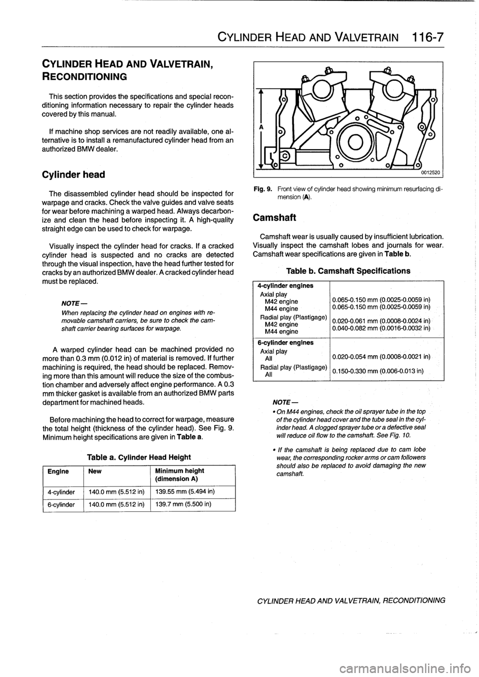
Fig
.
9
.
Front
víew
of
cylinder
head
showing
minimum
resurfacing
di-
warpage
and
cracks
.
Check
the
valve
guides
and
valveseats
mension
(A)
.
for
wear
before
machining
a
warped
head
.
Always
decarbon-
ize
and
clean
the
head
before
inspectiog
it
.
A
high-quality
Camshaft
straíght
edge
can
be
used
to
check
for
warpage
.
Camshaft
wear
is
usually
caused
by
insufficient
lubrication
.
Visually
inspect
the
cylinder
head
for
cracks
.
If
acracked
Visually
inspect
the
camshaft
lobes
and
journals
for
wear
.
cylinder
head
is
suspected
and
no
cracks
are
detected
Camshaftwear
specifications
are
given
in
Table
b
.
through
the
visual
inspection,
have
the
head
further
tested
for
cracks
byan
authorized
BMW
dealer
.
A
cracked
cylinder
head
Table
b
.
Camshaft
Specifications
must
be
replaced
.
4-cylinder
engines
Axialplay
M42
engine
0
.065-0
.150
mm
(0
.0025-0
.0059
in)
M44
engine
0
.065-0
.150
mm
(0
.0025-0
.0059
in)
Radial
play(Plastigage)
0
.020-0.061
mm
(0
.0008-0
.0024
in)
M42
engine
M44
engine
0
.040-0
.082
mm
(0
.0016-0
.0032
in)
6-cylinder
engines
A
warped
cylinder
head
can
be
machined
provided
no
Axial
pla
y
more
than
0
.3
mm
(0
.012
in)
of
material
is
removed
.
If
further
All
0
.020-0.054
mm
(0
.0008-0
.0021
in)
machining
is
required,
the
head
should
be
replaced
.
Remov-
Radial
play(Plastigage)
0
.150-0.330
mm
(0
.006-0.013
in)
ing
more
than
this
amount
will
reduce
the
size
of
the
combus-
All
tion
chamber
and
adversely
affect
engine
performance
.
A
0
.3
mm
thicker
gasket
is
available
from
an
authorized
BMW
parts
department
for
machined
heads
.
NOTE-
-
On
M44
engines,
check
the
oil
sprayer
tube
in
the
top
Before
machining
the
head
to
correct
for
warpage,
measure
of
the
cylinder
head
coverand
the
tubesea¡
in
the
cyl-
the
total
height(thicknessof
the
cylinder
head)
.
See
Fig
.
9
.
inderhead
.Acloggedsprayertubeoradefectiveseal
Minimum
height
specifications
are
given
in
Table
a
.
will
reduce
oil
flowto
the
camshaft
.
See
Fig
.
10
.
-
If
the
camshaft
is
being
replaced
due
to
cam
lobe
Table
a
.
Cylinder
Head
Height
wear,
the
corresponding
rockerarms
orcam
followers
Engine
New
Minimum
height
shouId
also
be
replaced
to
avofd
damaglng
the
new
(dimension
A)
camshaft
.
CYLINDER
HEAD
AND
VALVETRAIN,
RECONDITIONING
Page 92 of 759
116-
8
CYLINDER
HEAD
AND
VALVETRAIN
0012502
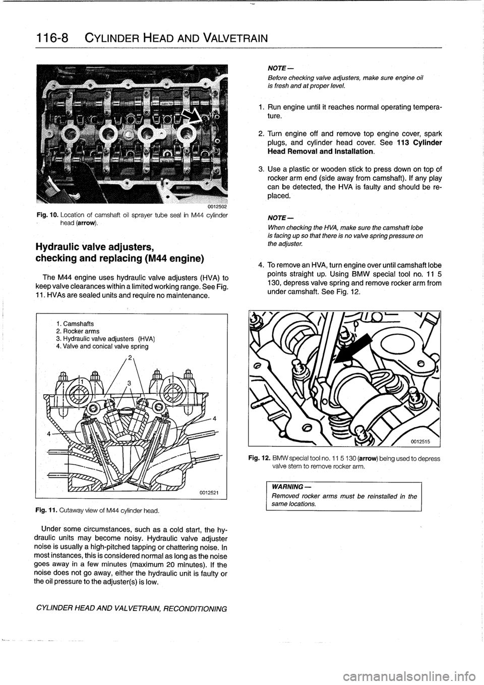
Fig
.
10
.
Location
of
camshaft
oil
sprayer
tube
sea¡
in
M44
cylinder
head
(arrow)
.
Hydraulic
valve
adjusters,
checking
and
replacing
(M44
engine)
The
M44
engine
uses
hydraulic
valveadjusters
(HVA)
to
keep
valve
clearances
within
a
limited
working
range
.
See
Fig
.
11
.
HVAs
are
sealed
units
and
require
no
maintenance
.
1
.
Camshafts
2
.
Rocker
arms
3
.
Hydraulic
valve
adjusters
(HVA)
4
.
Valve
and
conical
valve
spring
Fig
.
11
.
Cutaway
view
of
M44
cylinder
head
.
Under
some
circumstances,
such
as
a
cold
start,
thehy-
draulic
units
may
become
noisy
.
Hydraulic
valve
adjusternoise
is
usually
ahigh-pitched
tapping
or
chattering
noise
.
In
most
instances,
this
is
consídered
normal
aslong
as
the
noise
goes
away
in
a
few
minutes
(maximum20
minutes)
.
If
thenoise
does
not
go
away,
either
the
hydraulic
unit
is
faulty
orthe
oil
pressure
tothe
adjuster(s)
is
low
.
CYLINDER
HEAD
AND
VALVETRAIN,
RECONDITIONING
NOTE-
8efore
checking
valveadjusters,
make
sure
engine
oil
is
fresh
and
at
proper
level
.
1
.
Run
engine
until
it
reaches
normal
operating
tempera-
ture
.
2
.
Turn
engine
off
and
remove
top
engine
cover,
spark
plugs,
and
cylinder
head
cover
.
See
113
Cylinder
Head
Removal
and
Installation
.
3
.
Use
a
plastic
or
wooden
stick
to
press
down
on
top
of
rocker
armend
(side
away
from
camshaft)
.
If
any
play
can
be
detected,the
HVA
is
faulty
and
should
be
re-
placed
.
NOTE-
When
checking
the
HVA,
make
sure
the
camshaft
lobe
is
facing
upso
that
there
is
no
valve
spring
pressure
on
the
adjuster
.
4
.
To
remove
an
HVA,
turn
engine
over
until
camshaft
lobe
points
straight
up
.
Using
BMW
special
tool
no
.
11
5
130,
depress
valvespring
and
remove
rocker
arm
from
under
camshaft
.
See
Fig
.
12
.
Fig
.
12
.
BMW
special
tool
no
.
115
130
(arrow)
being
used
to
depress
valve
stem
to
remove
rocker
arm
.
WARNING
-
Removed
rocker
armsmustbe
reinstalled
in
the
same
locations
.
Page 93 of 759
5
.
Pull
hydraulic
valve
adjuster
straight
out
of
cylinder
head
.
See
Fig
.
13
.
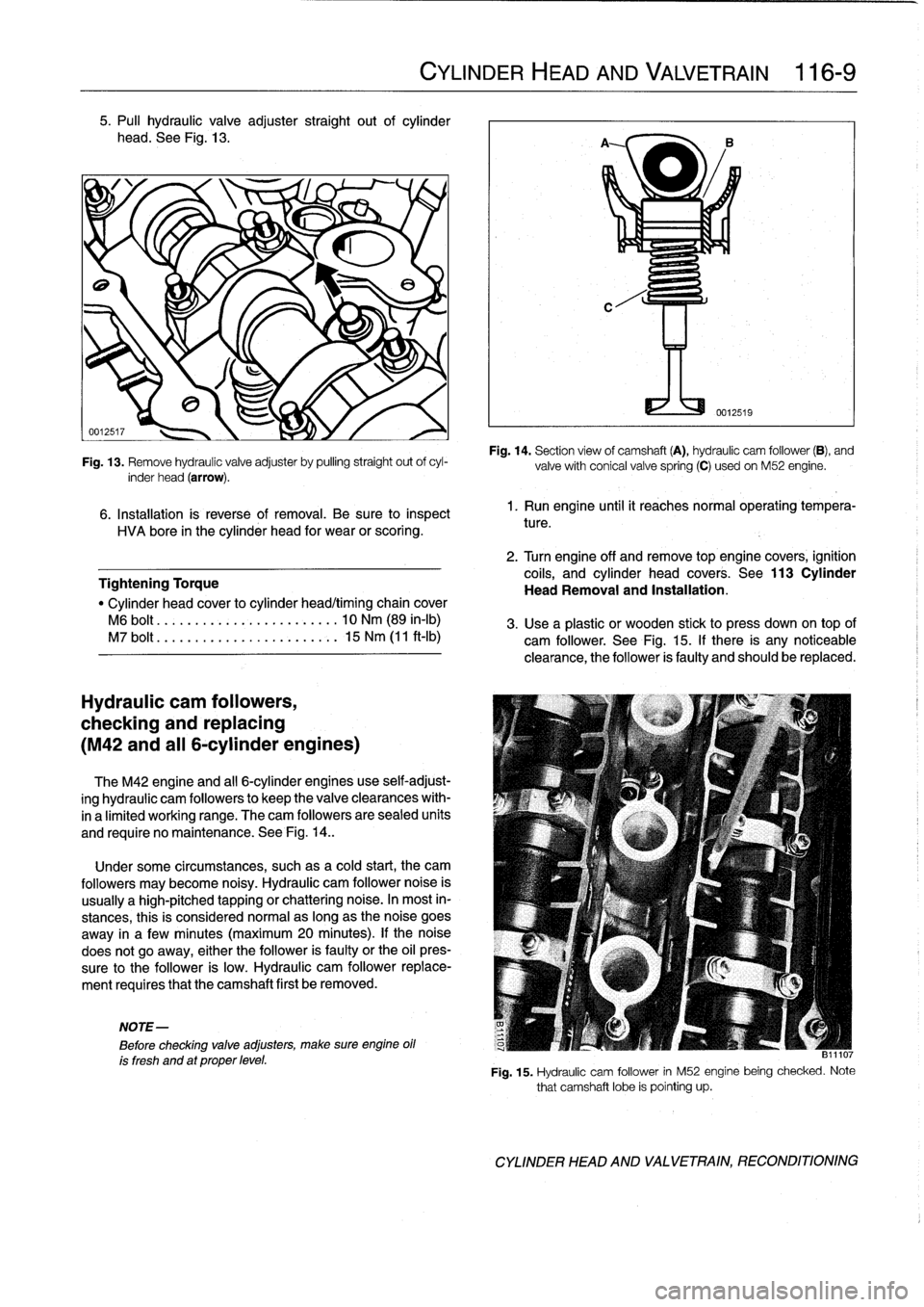
Fig
.
13
.
Remove
hydraulic
valve
adjuster
by
pulling
straight
out
ofcyl-
inder
head
(arrow)
.
6
.
Installation
is
reverse
of
removal
.
Be
sure
to
inspect
HVA
bore
in
the
cylinder
head
for
wear
or
scoring
.
Tightening
Torque
"
Cylinder
head
cover
to
cylinder
head/timing
chain
cover
M6
bolt
.........
..
..
...
........
10
Nm
(89
in-lb)
M7
bolt
.......
.
.
..
...
.
...
.
.....
15
Nm
(11
ft-Ib)
Hydraulic
cam
followers,
checking
and
replacing
(M42
and
al¡
6-cylinder
engines)
The
M42
engine
and
al¡
6-cylinder
engines
use
self-adjust-
ing
hydraulic
cam
followers
to
keep
the
valveclearances
with-
ina
limited
working
range
.
The
cam
followers
are
sealed
units
and
require
no
maintenance
.
See
Fig
.
14
.
.
Under
some
circumstances,
suchasa
cold
start,
the
cam
followers
may
become
noisy
.
Hydraulic
cam
follower
noise
is
usually
a
high-pitched
tapping
or
chattering
noise
.
In
most
in-
stances,
this
is
considered
normalas
long
as
the
noise
goes
away
in
a
fewminutes
(maximum
20
minutes)
.
lf
the
noise
does
not
go
away,
either
the
follower
is
faulty
or
the
oil
pres-
sure
to
the
follower
is
low
.
Hydraulic
cam
follower
replace-
ment
requires
that
the
camshaft
first
be
removed
.
NOTE-
Before
checking
valve
adjusters,
make
sure
engine
oil
ís
fresh
and
at
proper
level
.
CYLINDER
HEAD
AND
VALVETRAIN
116-
9
Fig
.
14
.
Section
view
of
camshaft
(A),
hydraulic
cam
follower
(B),
and
valvewith
conical
valvespring
(C)
usedon
M52
engine
.
1.
Run
engine
until
it
reachesnormal
operating
tempera-
ture
.
2
.
Turn
engine
off
and
remove
top
engine
covers,
ignition
coils,
and
cylinder
head
covers
.
See
113
Cylinder
Head
Removal
and
Installation
.
3
.
Use
a
plastic
or
wooden
stickto
press
down
on
top
of
cam
follower
.
See
Fig
.
15
.
If
there
is
any
noticeable
clearance,
the
follower
is
faulty
and
should
be
replaced
.
811107
Fig
.
15
.
Hydraulic
cam
follower
in
M52
enginebeing
checked
.
Note
that
camshaft
lobe
is
pointing
up
.
CYLINDER
HEAD
AND
VALVETRAIN,
RECONDITIONING
Page 94 of 759
116-
1
0
CYLINDER
HEADAND
VALVETRAIN
NOTE-
When
checking
a
cam
follower,
make
sure
the
corre-
sponding
camshaft
lobe
ís
facing
up
so
that
there
is
no
valve
spring
pressure
on
the
follower
.
4
.
To
replace
a
cam
follower,
remove
appropriate
cam-
shaft
.
Refer
to
camshaft
removal
procedures
given
ear-
lier
.
5
.
Once
camshaft
is
out
of
way,
withdraw
faulty
cam
fol-
lower
and
replace
with
new
one
.
Inspect
cam
follower
bores
for
wear
and
scoring
.
6
.
Camshaft,
timing
chain
and
cylinder
head
cover
reas-
sembly
is
reverse
of
disassembly
.
Tightening
Torques
"
Camshaft
bearing
caps
to
cylinder
head
M7
....
.
..
.
......
.
.....
...
.
..
.
15
Nm
(11
ft-Ib)
"
Cylinder
head
cover
to
cylinder
headltiming
chain
cover
M6
....
.
..
.
.
.
..........
...
.
.
..
10
Nm
(89
in-lb)
"
Timing
chain
hydraulic
tensioner
to
cylinder
head-see
117
Camshaft
Timing
Chain
"
Timing
chain
sprocket
to
camshaft
flange
(M6)-see
117
Camshaft
Timing
Chain
CYLINDER
HEAD
AND
VALVETRAIN,
RECONDITIONING
Table
c
.
Valve
Guide
Specifications
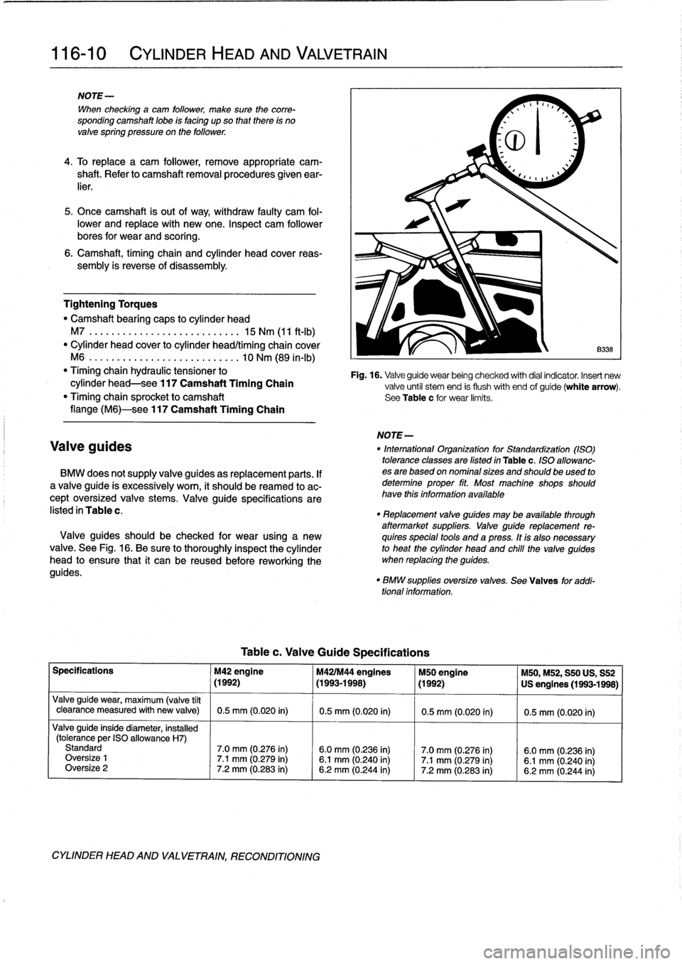
Fig
.
16
.
Valveguide
wear
being
checked
with
dial
indicator
.
Insert
new
valve
until
stem
end
is
flush
with
end
of
guide(white
arrow)
.
See
Table
c
for
wear
limits
.
NOTE-
Valve
guides
"
Intemational
Organization
for
Standardization
(ASO)
tolerance
classes
are
Gsted
in
Table
c
.
ISO
allowanc
BMW
does
notsupply
valve
guides
as
replacement
parts
.
If
esare
based
on
nominal
sizes
and
should
beused
to
a
valve
guide
is
excessively
worn,
it
should
be
reamed
to
ac-
determine
proper
fit
.
Most
machine
shops
should
cept
oversized
valve
stems
.
Valve
guide
specifications
are
have
thís
informationavailable
listed
in
Table
c
.
"
Replacement
valve
guides
may
be
available
through
aftermarket
suppliers
.
Valve
guide
replacement
re-
Valve
guides
should
be
checked
for
wear
using
a
new
quires
specíal
tools
and
a
press
.
It
is
also
necessary
valve
.
See
Fig
.
16
.
Be
sure
to
thoroughly
inspect
the
cylinder
to
heat
the
cylinder
head
and
chile
the
valve
guides
head
to
ensure
that
it
can
be
reused
before
reworking
the
when
replacing
the
guides
.
guides
.
"
BMW
suppllesoversize
valves
.
Sea
Valves
for
addi-
tional
information
.
Specifications
M42
engine
M421M44
engines
M50
engine
M50,M52,
S50
US,
S52
~
(1992)
~
(1993-1998)
~
(1992)
~
US
engines
(1993-1998)
Valve
guide
wear,
maximum
(valve
tílt
clearance
measured
with
new
valve)
0
.5
mm
(0
.020
in)
0
.5
mm
(0
.020
in)
0
.5
mm
(0
.020
in)
0
.5
mm
(0
.020
in)
Valveguide
inside
diameter,
installed
(tolerance
per
ISO
allowance
H7)
Standard
7
.0
mm
(0
.276
in)
6
.0
mm
(0
.236
in)
7
.0
mm
(0.276
in)
6
.0
mm
(0
.236
in)
Oversize
1
7
.1
mm
(0
.279
in)
6
.1
mm
(0
.240
in)
7
.1
mm
(0.279
in)
6
.1
mm
(0
.240
in)
Oversize
2
7
.2
mm
(0
.283
in)
6
.2
mm
(0
.244
in)
7
.2
mm
(0
.283
in)
6
.2
mm
(0
.244
in)
Page 95 of 759
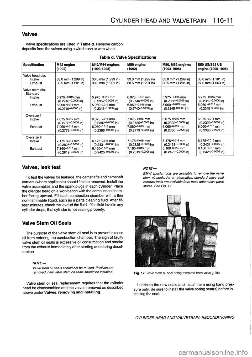
Valves
Valve
specifications
are
listed
in
Table
d
.
Remove
carbon
deposits
from
thevalves
using
a
wire
brush
or
wire
wheel
.
Specification
M42
engine
M42IM44
engines
M50
engine
M50,
M52
engines
S50
USIS52
US
(1992)
(1993-1998)
(1992)
(1993-1998)
I
engine
(1995-1998)
Valve
head
dia
.
Intake
133
.0
mm
(1
.299
in)
133
.0
mm
(1
.299
in)
33
.0
mm
(1
.299
in)
33
.0
mm
(1
.299
in)
130
.0
mm
(1
.181
in)
Exhaust
30
.5
mm
(1
.201
in)
30
.5
mm
(1
.201
in)
30
.5
mm
(1
.201
in)
~
30
.5
mm
(1
.201
in)
27
.0
mm
(1
.063
in)
Valve
stem
dia
.
Standard
Intake
6
.975-0
.015
mm
5
.975-0
.015
mm
6
.975-0
.015
mm
5
.975-0
.015
mm
5
.975-0015
mm
(0
.2746-00006
in)
(0
.2352-00006
in)
(0
.2746-00006
in)
(0
.2352-00006
in)
(0
.2352
-
00006
in)
Exhaust
6
.960-0015
mm
5
.960-0
.015
mm
6
.960
--0
.015
mm
5
.960
-0
.015
mm
5
.960-0
.015
mm
(0
.2740-00006
in)
(0
.2345-0
.0006
in)
(0
.2740--0
.0006
in)
(0
.2345-0
.0006
in)
(0
.2345-0
.0006
in)
Intake
7
.075-0
.015
mm
6
.075-0
.015
mm
7
.075-0
.015
mm
6
.075-0
.015
mm
6
.075-0
.015
mm
(0
.2785-00006
in)
(0
.2392-0
.0006
in)
(0
.2785-00006
in)
(0
.2392
-
00006
in)
(0
.2392-00006
in)
Exhaust
7
.060-0015
mm
6
.060-0015
mm
7
.060-0
.015
mm
6
.060-0015
mm
6
.060-0015
mm
(0
.
2779-0
.0006
in)
(0
.2386-00006
in)
(0
.2779-00006
in)
(0
.2386-00006
in)
(0
.2386-00006
in)
Oversize
2
Intake
7
.175-0
.015
mm
6
.175-0
.015
mm
7
.175-0
.015
mm
6
.175-0
.015
mm
6
.175-0
.015
mm
(0
.2825-00006
in)
(0
.2431-00006
in)
(0
.2825-00006
in)
(0
.2431--0
.0006
in)
(0
.2431-00006
in)
Exhaust
7
.160-0015
mm
6
.160-0015
mm
7
.160-0
.015
mm
6
.160-0015
mm
6
.160-0-015
mm
(0
.2819
-
00006
i
n
)
(0
.2425-00006
in)
(0
.2819-00006
in)
(0
.2425-00006
in)
(0
.2425-00006
in)
Valves,
leak
test
NOTE-
BMW
speclal
tools
are
available
to
remove
the
valve
To
test
thevalves
for
leakage,
the
camshafts
and
camshaft
stem
oil
seals
.
As
an
alternative,
standard
valvesea¡
carriers
(where
applicable)
should
first
be
removed
.
Instali
the
removal
tools
are
available
from
most
automotive
parts
valve
assemblies
and
the
spark
plugs
in
each
cylinder
.
Place
stores
.
See
Flg
.
17
.
the
cylinder
head
on
a
workbench
with
the
combustion
cham-
ber
facing
upward
.
Fill
each
combustion
chamber
with
a
thin
non-flammable
liquid,
suchas
a
parts
cleaning
fluid
.
After
fif-
teenminutes,
check
the
leve¡
of
the
fluid
.
If
the
fluid
level
in
any
cylinder
drops,
thatcylinder
is
not
sealing
properly
.
Valve
Stem
Oil
Seals
The
purpose
of
the
valve
stem
oil
sea¡
is
to
prevent
excess
oil
from
entering
the
combustion
chamber
.
The
sign
offautty
valve
stem
oil
seals
is
excessive
oil
consumption
and
smoke
from
the
exhaust
immediately
after
starting
and
during
decel-
erat¡on
NOTE-
Valve
stem
oil
seals
should
not
be
reused
.
ff
valves
are
removed,
new
valve
stem
oil
seals
should
be
installed
.
Valve
stem
oil
sea¡
replacement
requires
that
the
cylinder
head
be
disassembled
and
thevalves
removed
as
described
above
under
Valves,
removing
and
installing
.
CYLINDER
HEAD
AND
VALVETRAIN
116-
11
Table
d
.
Valve
Specifications
Fig
.
17
.
Valve
stem
oil
sea¡
being
removed
from
valve
guide
.
Lubricate
the
new
seals
and
insta¡]
them
using
hand
pres-
sure
only
.
Be
sure
to
install
the
valve
spring
seat(s)
before
in-
stalling
the
sea¡
.
CYLINDER
HEAD
AND
VALVETRAIN,
RECONDITIONING
Page 96 of 759
116-12
CYLINDER
HEADAND
VALVETRAIN
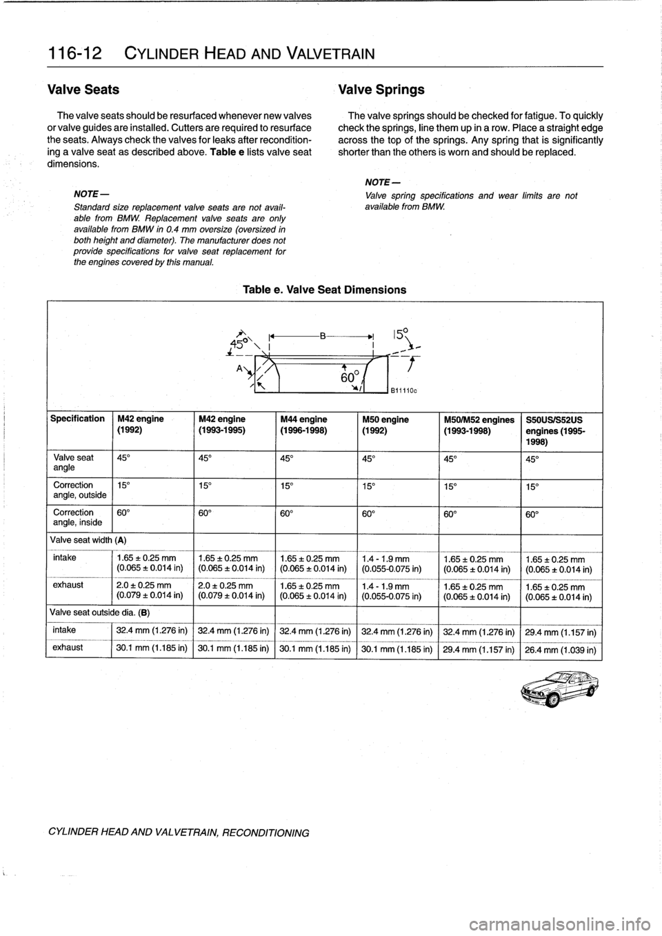
Valve
Seats
Valve
Springs
The
valve
seats
should
be
resurfaced
whenever
new
valves
The
valvesprings
should
be
checked
for
fatigue
.
To
quickly
or
valve
guides
are
installed
.
Cutters
are
required
to
resurface
check
the
springs,
line
them
up
in
a
row
.
Place
a
straight
edge
the
seats
.
Always
check
thevalves
for
leaks
after
recondition-
across
thetop
of
the
springs
.
Any
spring
that
is
significantly
ing
a
valve
seat
as
described
above
.
Table
e
lists
valve
seat
shorter
than
theothers
is
worn
and
should
be
replaced
.
dimensions
.
NOTE-
NOTE-
Valve
spring
specifications
and
wear
límits
arenot
Standard
size
replacement
valve
seats
are
not
avail-
available
from
BMW
.
ablefrom
BMW
.
Replacement
valve
seats
are
only
available
from
BMW
in
0
.4
mm
oversize
(oversized
in
both
height
and
diameter)
.
The
manufacturer
does
not
provide
specífications
for
valve
seat
replacement
for
the
enginescovered
by
this
manual
.
Table
e
.
Valve
Seat
Dimensions
"Y
Valve
seat
outside
dia
.
(B)
CYLINDER
HEAD
AND
VALVETRAIN,
RECONDITIONING
60
°
yl
1
B11110c
Specification
M42
engine
M42
engine
M44
engine
M50
engine
M501M52
engines
S50USIS52US
(1992)
(
(1993-1995)
I
(1996-1998)
(1992)
I
(1993-1998)
I
engines
(1995-
1998)
Valve
seat
45°
451
145°
145°
(
45°
145°
angle
Correction
1
15°
15°
115°
(
15°
15°
15
angle,
outside
Correction
60°
60°
I60°
60°
I60°
I60°
angle,
inside
Va
lve
seat
width
(A)
intake
1
1
.65
±0
.25
mm
1
1.65
±0
.25
mm
1
1
.65
t
0
.25
mm
1
1
.4
-1
.9
mm
1
1
.65
±0
.25
mm
1
1
.65
±
0
.25
mm
(0
.065
+0
.014
in)
I
(0.065
t
0
.014
in)
(0
.065
:E
0
.014
in)
(0
.055-0.075
in)
(0
.065
t
0
.014
in)
l(0
.065t0
.014
in)
____
___
exhaust
12
.0
±0
.25
mm
12
.0
t
0
.25
mm
1
1
.65
t
0
.25
mm
1
1
.4
-
1
.9
mm
11
.65
±
0
.25
mm
1
1
.65
:t
0
.25
mm
(0.079
±
0
.014
in)
1
(0
.079
t0
.014
in)
1
(0
.065
±
0
.014
in)
1
(0
.055-0.075
in)
1
(0
.065
t
0
.014
in)
1
(0.065
t0
.014
in)
intake
32
.4
mm
(1
.276
in)
32
.4
mm
(1
.276m)
32
.4
mm
(1
.276
in)
32
.4
mm
(1
.276
in)
32
.4
mm
(1
.276
in)
29
.4
mm
(1
.157
in)
exhaust
30
.1
mm
(1
.185
in)
30
.1
mm
(1
.185
in)
30
.1
mm
(1
.185
in)
30
.1
mm
(1
.185
in)
29
.4
mm
(1
.157
in)
26
.4
mm
(1
.039
in)
Page 99 of 759
NOTE-
The
vibration
damper
center
bolt
is
very
tight
.
A
heavy
duty
holding
device,
such
as
BMW
special
tool
no
.
112
150,
should
be
used
to
hold
the
vibration
damper
hub
V
stationary
while
the
bolt
is
loosened
.
v
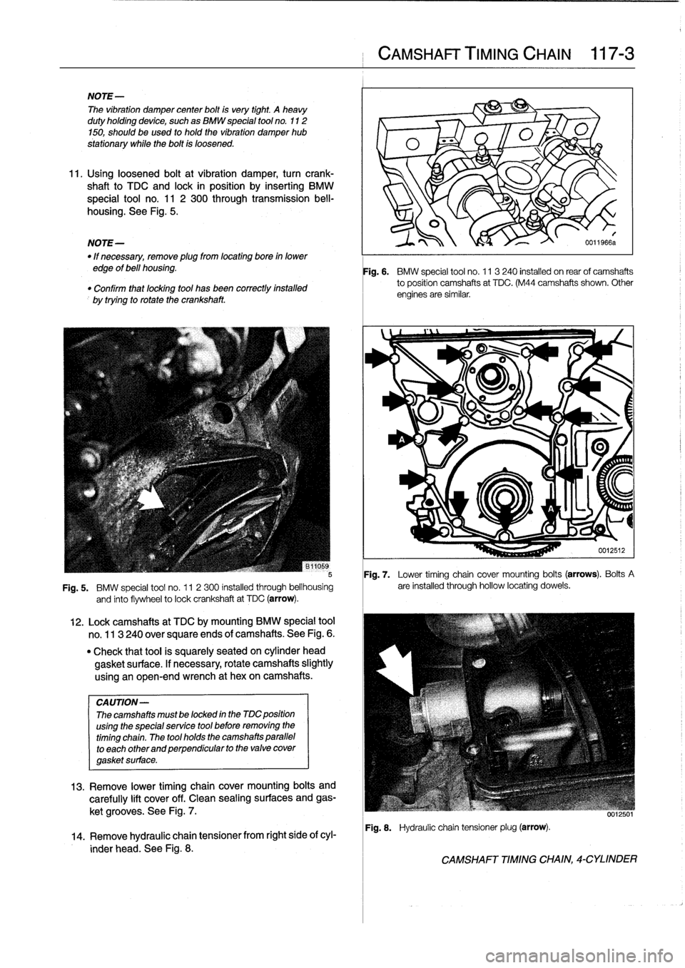
11
.
Usingloosened
bolt
at
vibration
damper,
turn
crank-
shaft
to
TDC
and
lock
in
position
by
inserting
BMW
special
tool
no
.
11
2
300
through
transmission
bell-
-
p
housing
.
See
Fig
.
5
.
v
O
NOTE-
I\
0011966a
"
If
necessary,
remove
plugfrom
locating
boye
in
lower
edge
of
bell
housing
.
"
Confirm
that
locatng
tool
has
been
correctlyinstalled
by
trying
to
rotate
the
crankshaft
.
Fig
.
7
.
Lower
timing
chain
cover
mounting
bolts
(arrows)
.
Bolts
A
Fig
.
5
.
BMW
special
tool
no
.
11
2300
installed
through
bellhousing
are
installed
through
hollow
locating
dowels
.
and
finto
flywheel
to
lock
crankshaft
at
TDC
(arrow)
.
CA
UTION-
Thecamshafts
mustbe
locked
in
the
MC
position
using
the
specialservice
tool
before
removing
the
timing
chain
.
The
tool
holds
the
camshafts
parallel
to
each
other
and
perpendicular
to
the
valve
cover
gasket
surface
.
12
.
Lockcamshafts
at
TDC
bymounting
BMW
special
tool
no
.
113
240
over
square
ends
of
camshafts
.
See
Fig
.
6
.
"
Check
that
tool
is
squarely
seated
on
cylinder
head
gasket
surface
.
If
necessary,
rotate
camshafts
slightly
using
an
open-end
wrench
at
hexon
camshafts
.
13
.
Remove
lower
timing
chaincover
mounting
bolts
and
carefully
lift
cover
off
.
Clean
sealing
surfaces
and
gas-
ket
grooves
.
See
Fig
.
7
.
14
.
Remove
hydraulic
chaintensioner
from
right
side
of
cyl-
inder
head
.
See
Fig
.
8
.
CAMSHAFT
TIMING
CHAIN
117-
3
Fig
.
6
.
BMW
special
tool
no
.
11
3240
installed
on
rearof
camshafts
to
position
camshafts
at
TDC
.
(M44
camshafts
shown
.
Other
engines
are
similar
.
Fig
.
8
.
Hydraulic
chain
tensionerplug
(arrow)
.
CAMSHAFT
TIMING
CHAIN,
4-CYLINDER
Page 101 of 759
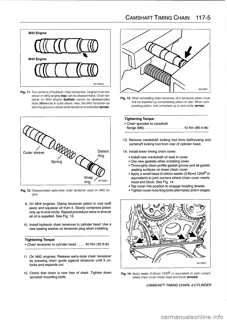
M42
Engine
CL
(EM
Fig
.
11
.
Two
versionsof
hydraulic
chaintensioners
.
Original
chain
ten-
sioner
on
M42
engine
(top)
canbe
disassembled
.
Chain
ten-
sioner
on
M44
engine
(bottom)
cannot
be
disassembled
.
Note
differences
in
outer
sleeve
.
Also,
the
M42
tensioner
de-
tent
ring
groove
is
visible
when
tensioner
is
extended
(arrow)
.
Outer
sleeve
Spring
0013024a
Detent
ring
9
.
On
M44
engines
:
Clamp
tensioner
piston
in
vice
(soft
jaws)
and
squeeze
oil
from
it
.
Slowly
compress
piston
only
up
to
end
círclip
.
Repeat
procedure
twice
to
ensure
al¡oil
is
expelled
.
See
Fig
.
13
.
10
.
Insta¡¡
hydraulic
chain
tensioner
lo
cylinder
head
.
Usea
new
sealing
washer
on
tensionerplug
when
installing
.
Tightening
Torque
"
Chain
tensioner
to
cylinder
head
....
40
Nm
(30
ft-Ib)
11
.
On
M42
engines
:
Release
early-style
chain
tensioner
by
pressing
chain
guide
against
tensioner
until
it
un-
locks
and
expands
out
.
CAMSHAFT
TIMING
CHAIN
117-
5
0012507
Fig
.
13
.
When
reinstalling
chain
tensiones,
oil
in
tensioner
piston
must
first
be
expelled
by
compressing
piston
in
vise
.
When
com-
pressing
piston,
only
compress
up
to
and
circlip
(arrow)
.
Tightening
Torque
"
Chain
sprocket
lo
camshaft
flange
(M6)
..
.
..
.............
.
..
10
Nm
(89
in-lb)
13
.
Remove
crankshaft
locking
tool
from
bellhousing
and
camshaft
locking
tool
from
rear
of
cylinder
head
.
14
.
Install
lower
timingchain
cover
:
"
Insta¡¡
new
crankshaft
oil
seal
in
cover
.
"
Use
new
gaskets
when
installing
cover
.
"
Thoroughly
clean
profile
gasketgroove
and
all
gasket
sealing
surfaces
on
lowerchaincover
.
"
Apply
a
small
bead
of
silicon
sealer
(3-Bond
1209
or
Snap
equivalent)
lo
joint
corners
where
chaincover
meets
ring
0013024
head
and
block
.
See
Fig
.
14
.
"
Tap
cover
into
position
to
engage
locating
dowels
.
Fig
.
12
.
Disassembled
early-style
chain
tensioner
usadon
M42
en-
"
Tighten
cover
mounting
bolts
alternately
and
in
stages
.
gine
.
12
.
Check
that
chain
is
now
free
of
siack
.
Tighten
down
sprocket
mounting
bolts
.
where
chain
cover
meets
head
and
block
(arrows)
.
Fig
.
14
.
Apply
sealer
(3-Bond
1209
0
or
equivalent)
to
joint
corners
CAMSHAFT
TIMING
CHAIN,
4-CYLINDER
Page 102 of 759
117-
6
CAMSHAFT
TIMING
CHAIN
15
.
Insta¡¡
upper
timing
chaincover
:
17
.
Remove
crankshaft
locking
tool
from
transmission
bell-
"
Thoroughly
clean
profile
gasketgroove
and
all
sealing
housing
and
camshaft
locking
tool
from
rear
of
cylinder
surfaces
.
head
.
"
Applya
small
bead
ofsilicon
sealer
(3-Bond
1209®
or
equivalent)
to
upper
and
lower
joint
comers
where
18
.
Turn
engine
over
by
hand
in
direction
of
rotation
at
least
chaincover
meets
cylinder
head
.
two
full
rotations
.
Reinstall
camshaft
and
crankshaft
"
Insta¡¡
new
profile
gasket
to
groove
in
lowerchain
cover
.
locking
tools
to
check
engine
timing
.
Repeat
cam
timing
"
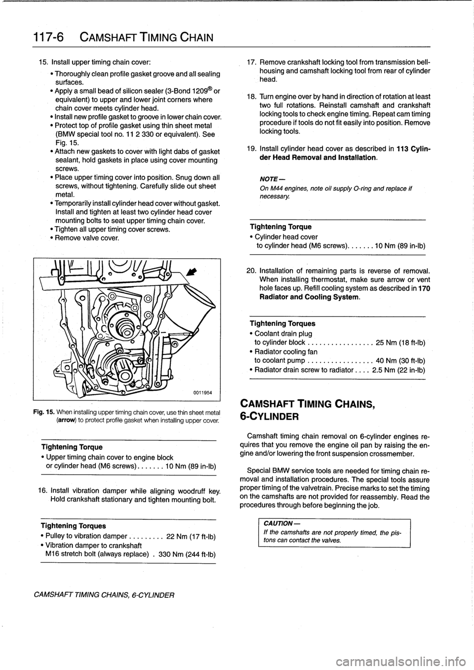
Protect
top
of
profile
gasket
using
thin
sheetmetal
procedure
if
tools
do
not
fit
easily
into
position
.
Remove
(BMW
special
tool
no
.
11
2
330
or
equivalent)
.
See
locking
tools
.
Fig
.
15
.
"
Attach
new
gaskets
to
cover
with
light
dabs
of
gasket
19
.
Install
cylinder
head
cover
as
described
in
113
Cylin-
sealant,
hold
gaskets
in
placeusing
cover
mounting
der
HeadRemoval
and
Installation
.
screws
.
"
Place
upper
timing
cover
into
position
.
Snug
down
al¡
NOTE-
screws,
without
tightening
.
Carefully
slide
out
sheet
OnM44
engines,
note
oil
supply
O-ring
and
replace
ff
metal
.
necessary
.
"
Temporarily
install
cylinder
head
cover
without
gasket
.
Insta¡¡
and
tighten
at
least
two
cylinder
head
cover
mounting
bolts
to
seat
upper
timing
chaincover
.
"
Tighten
all
upper
timing
cover
screws
.
Tightening
Torque
"
Remove
valve
cover
.
"
Cylinder
head
cover
to
cylinder
head
(M6
screws)
...
..
.
.
10
Nm
(89
ín-Ib)
-
CAMSHAFT
TIMING
CHAINS,
Fig
.
15
.
When
installing
upper
timing
chain
cover,
use
thin
sheetmetal
6-CYLINDER
(arrow)
to
protect
profile
gasket
when
installing
uppercover
.
Tightening
Torque
"
Upper
timing
chaincover
to
engine
block
or
cylinder
head
(M6
screws)
....
.
..
10
Nm
(89
in-lb)
16
.
Install
vibration
damper
while
aligning
woodruff
key
.
Hold
crankshaft
stationary
and
tighten
mounting
bolt
.
Tightening
Torques
I
CAUTION-
"
Pulley
to
vibration
damper
..
.
.
.
....
22
Nm
(17
ft-Ib)
lf
the
camshaftsare
not
properly
timed,
the
1
pis-
tons
can
contact
thevalves
.
"
Vibration
damper
tocrankshaft
M16
stretch
bolt
(always
replace)
.
330
Nm
(244
ft-Ib)
CAMSHAFT
TIMINGCHAINS,
6-CYLINDER
20
.
Installation
of
remaining
parts
is
reverse
of
removal
.
When
installing
thermostat,
make
sure
arrow
or
vent
hole
faces
up
.
Refill
cooling
system
as
described
in
170
Radiator
and
Cooling
System
.
Tighteníng
Torques
"
Coolant
drain
plug
to
cylinder
block
.
..
.
.
.
...
.
..
.....
25
Nm
(18
ft-Ib)
"
Radiator
cooling
fan
to
coolant
pump
.
..
.
...
...
..
.....
40
Nm
(30
ft-Ib)
"
Radiator
drain
screw
to
radiator
....
2
.5
Nm
(22
in-lb)
Camshaft
timing
chainremovalon
6-cylinder
engines
re-
quires
that
you
Rmove
the
engine
oil
pan
by
raising
the
en-
gine
and/or
lowering
the
front
suspension
crossmember
.
Special
BMW
service
tools
are
needed
for
timing
chain
re-
moval
and
installation
procedures
.
The
special
tools
assure
proper
timing
of
the
valvetrain
.
Precise
marks
to
setthe
timing
on
the
camshafts
arenot
provided
for
reassembly
.
Read
the
procedures
through
before
beginning
thejob
.
Page 103 of 759
Camshaft
timing
chains,
removing
(6-cylinder
engines)
1
.
Disconnect
negative
(-)
cable
from
battery
.
CA
UTION-
Disconnecting
the
battery
may
erase
fault
codes)
stored
in
control
module
memory
.
Check
for
fault
codes
using
special
BMW
diagnostic
equipment
.
2
.
Drain
engine
coolant
.
Drain
engine
block
by
removing
block
drain
.
Remove
radiator
cooling
fan
shroud
and
cooling
fan
.
See170
Radiator
and
Cooling
System
.
.
WARNING
-
Allow
the
engine
to
cool
before
openingor
draining
the
system
.
CAUTION-
Radiator
fan
has
left
hand
threads
.
NOTE-
The
block
drain
plug
is
located
on
the
exhaust
side
of
the
engine,
below
cylinder
no
.
4
.
3
.
Drain
engine
oíl
andremove
oil
pan
.
See
119
Lubrica-
tion
System
.
4
.
Remove
alternator
cooling
duct
.
5
.
Remove
two
large
coolant
hoses
from
thermostat
housing
.
Remove
engine
lifting
bracket
and
thermostat
housing
from
front
of
cylinder
head
.
6
.
Loosen
bolts
for
coolant
pump
pulley
.
Then
remove
drive
belts
for
alternator
andA/C
compressor
.
See
020
Maintenance
Program
.
Remove
coolant
pump
pulley
.
Fig
.
16
.
NOTE-
OnM50
engines
with
a
two-roller
drive
belt
tensioner,
remove
the
upper
rollerto
access
thetensioner
mount-
ing
bolts
.
NOTE-
Make
note
of
the
arrangement
of
the
rubber
insulators
when
removing
the
cylinder
head
cover
mounting
bolts
.
CAMSHAFT
TIMING
CHAIN
117-
7
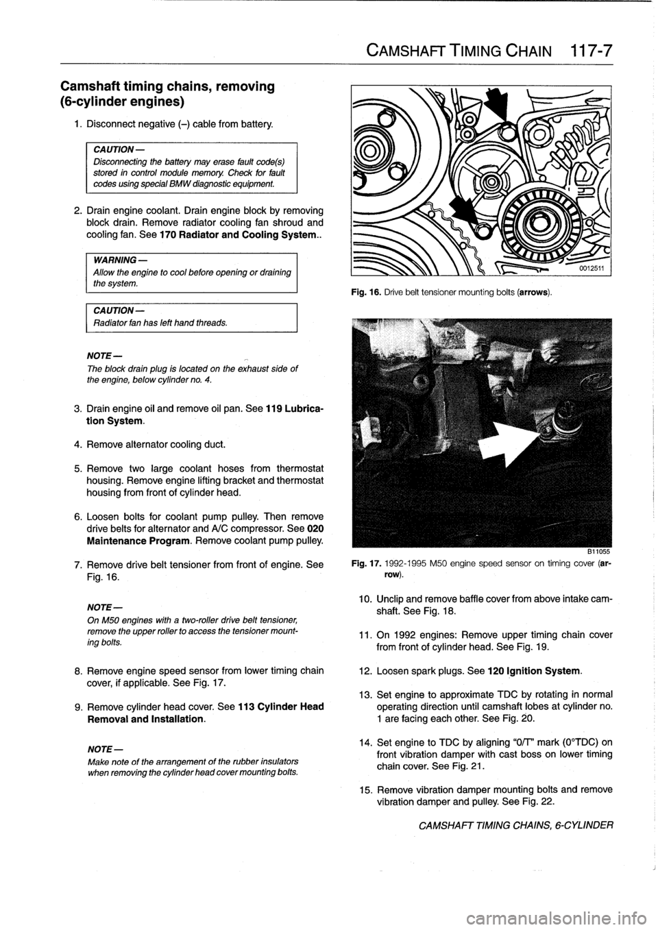
Fig
.
16
.
Drive
belt
tensioner
mounting
bolts
(arrows)
.
B11055
7
.
Remove
drive
belt
tensioner
from
front
of
engine
.
See
Fig
.
17
.
1992-1995
M50
engine
speed
sensor
on
timing
cover
(ar-
row)
.
10
.
Unclip
andremove
baffle
cover
from
above
intake
cam-
shaft
.
See
Fig
.
18
.
11
.
On
1992
engines
:
Remove
upper
timing
chain
cover
from
front
of
cylinder
head
.
See
Fig
.
19
.
8
.
Remove
engine
speed
sensor
from
lower
timing
chain
12
.
Loosen
spark
plugs
.
See
120
Ignition
System
.
cover,
if
applicable
.
See
Fig
.
17
.
13
.
Set
engine
to
approximate
TDC
by
rotating
in
normal
9
.
Remove
cylinder
head
cover
.
See
113
Cylinder
Head
operating
direction
until
camshaft
lobes
at
cylinder
no
.
Removal
and
Installatíon
.
1
are
facing
each
other
.
See
Fig
.
20
.
14
.
Set
engine
to
TDC
by
aligning
"0/T'
mark
(0°TDC)on
front
vibration
damper
with
cast
bosson
lower
timing
chain
cover
.
See
Fig
.
21
.
15
.
Remove
vibration
damper
mounting
bolts
and
remove
vibration
damper
and
pulley
.
See
Fig
.
22
.
CAMSHAFT
TIMING
CHAINS,
6-CYLINDER