Timing BMW M3 1998 E36 Workshop Manual
[x] Cancel search | Manufacturer: BMW, Model Year: 1998, Model line: M3, Model: BMW M3 1998 E36Pages: 759
Page 3 of 759
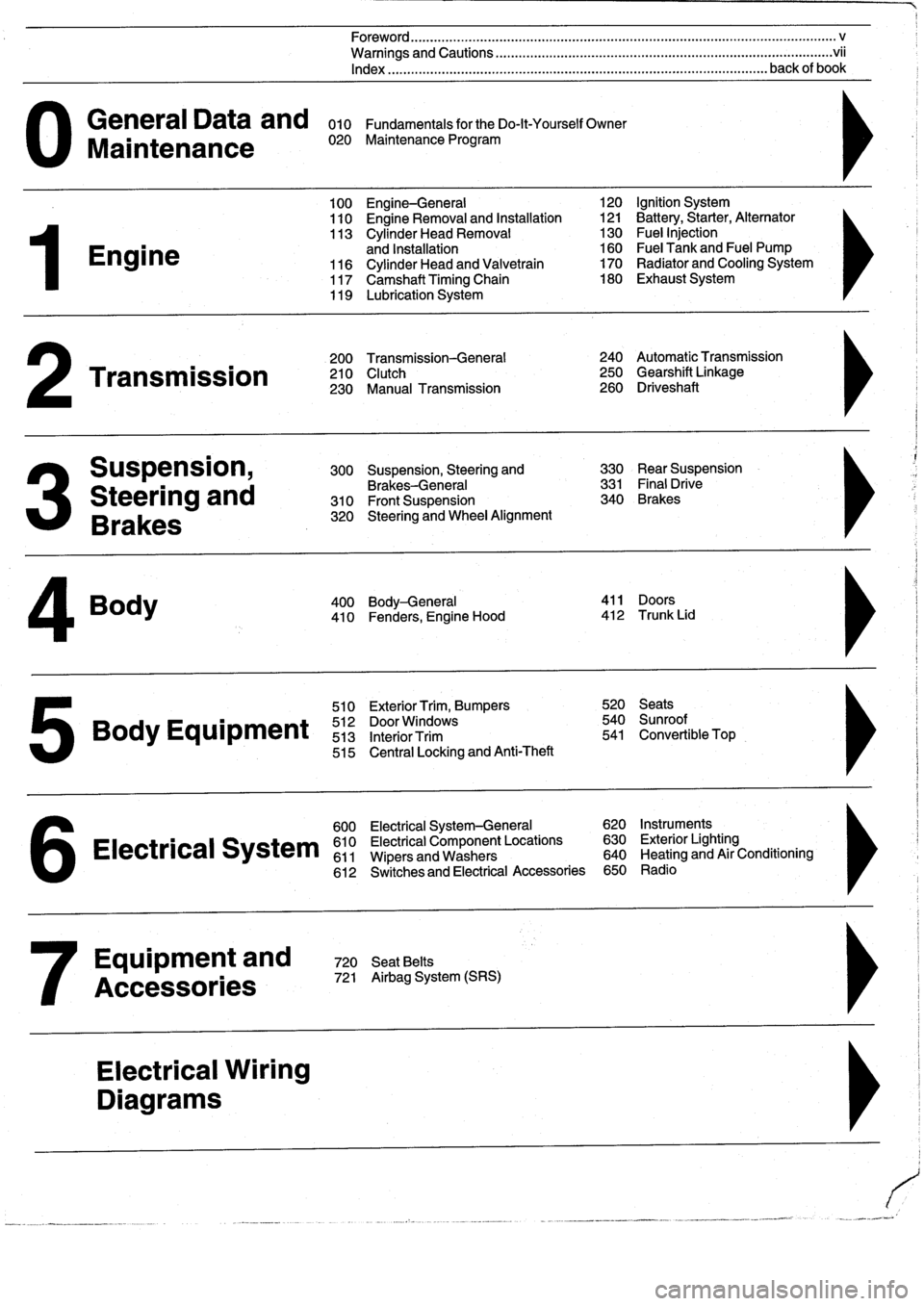
General
Data
and
010
FundamentalsfortheDo-lt-YourselfOwner
Maintenance
020
Maintenance
Program
Engine
Transmission
Suspension,
Steering
and
Brakes
4
Body
100
Engine-General
110
Engine
Removal
and
Installation
113
Cylinder
Head
Removal
and
Installation
116
Cylinder
Head
and
Valvetrain
117
Camshaft
Timing
Chain
119
Lubrication
System
200
Transmission-General
210
Clutch
230
Manual
Transmission
510
Exterior
Trim,
Bumpers
520
Seats
Bo
y
Equipment
512
DoorWTdws
540
nr
t
513
InteriorTrim
541
Convertible
Top
515
Central
Locking
and
Anti-Theft
600
Electrical
System-General
620
Instruments
Electrical
S
stem
610
Electrical
Component
Locations
630
Exterior
Lighting
611
Wipers
and
Washers
640
Heating
and
Air
Conditioning
6
612
Switches
and
Electrical
Accessories
650
Radio
Equipment
and
720
SeatBelts
Accessories
721
Airbag
System
(SRS)
Electrical
Wiring
Diagrams
Foreword
.
...
.
.
.
..................
.
.
.
.....
.
............
.
...
.
.
.
.
.
................
.
.
.
.....
.
......
.
................
.
.
.
.....
v
Warnings
and
Cautions
.....
.
...
.
.
.
.
.
..........
.
...
.
.
.
.
.
......
.
.........
.
.
.
...
.
.
.
......
.
.
.
.
.
............
.
.
.
.
.
.
.vii
Index
..............
.
.
.
.....
.
............
.
...
.
.
.
.
.
........
.
...
.
.
.
.
.
.......
.
......
.
...
.
.
.
.
.
.
.
........
.
.
.
..
back
of
book
300
Suspension,
Steering
and
330
RearSuspension
Brakes-General
331
Final
Drive
310
Front
Suspension
340
Brakes
320
Steering
and
Wheel
Alignment
400
Body-General
411
Doors
410
Fenders,
Engine
Hood
412
Trunk
Lid
120
Ignition
System
121
Battery,Starter,
Alternator
130
Fue¡
Injection
160
Fuel
Tank
and
Fuel
Pump
170
Radiator
and
Cooling
System180
Exhaust
System
240
Automatic
Transmission
250
Gearshift
Linkage
260
Driveshaft
Page 43 of 759
GENERAL
.
.....
.
.
.
.
.
.
.
...
.
.
.
.
.
.
.
.
.
...
100-1
Cylinder
Block
and
Crankshaft
.
.
.
.
.
.
.
.
.
...
100-1
Connecting
Rods
and
Pistons
.
.
.
.
.
.
.
.
.
.
.
.
.
100-1
Cylinder
Head
and
Valvetrain
.
.
.
.
.
.
.
.
.
.
.
.
.
100-2
VANOS
(Variable
Valve
Timing)
.
.
.
.
.
.
.
.
...
100-2
DISA
(Dual
Resonance
Intake
System)
.
.
.
.
.
100-3
Engine
Management
System
.
.
.
.
.
.
.
.
.
.
.
.
.
100-3
Ignition
......
.
.
.
.........
.
.
.
.
.
.
.
.
.
.
.
.
100-5
Fuel
Delivery
..
.
.
.
.....
.
...
.
.
.
.
.
.
.
.
.
.
.
.
100-5
Cooling
System
.
...........
.
.
.
.
.
.....
.
.
100-5
Lubrication
System
.........
.
.
.
.
.
.
.
.
.
.
.
.
100-5
MECHANICALTROUBLESHOOTING
.
.
.
.
100-5
Warnings
and
Cautions
..
.
...
.
.
.
.
.
.
.
.
.
.
.
.
100-5
Cylinder
compression,
checking
.
.
.
.
.
.
.
.
.
.
.
100-6
EngineMechanical
Troubleshooting
Table
.
.
.
100-7
DRIVEABILITY
TROUBLESHOOTING
...
100-8
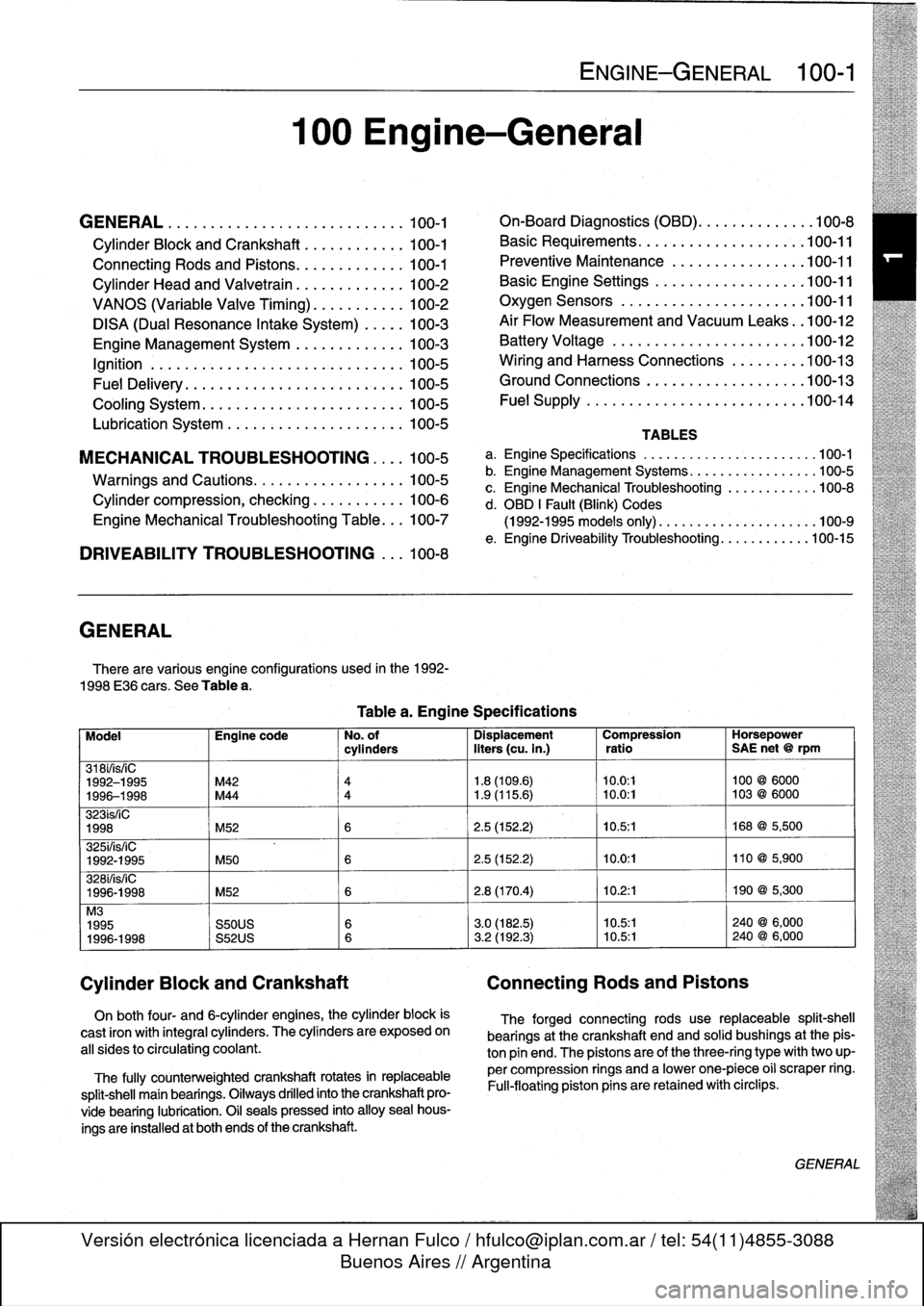
GENERAL
There
are
various
engíne
configurations
used
in
the
1992-
1998
E36
cars
.
See
Table
a
.
On
both
four-
and
6-cylinder
engines,
the
cylinder
block
is
cast
¡ron
with
integral
cyiinders
.
The
cyiinders
are
exposed
on
all
sides
to
circulating
coolant
.
The
fully
counterweighted
crankshaft
rotates
in
replaceable
split-shell
main
bearings
.
Oiiways
drilled
into
the
crankshaft
pro-
vide
bearing
lubrication
.
O¡I
seals
pressed
into
alloy
sea¡
hous-
ings
are
installedat
both
ends
of
the
crankshaft
.
100
Engine-General
Tablea
.
Engine
Specifications
ENGINE-GENERAL
100-1
On-Board
Diagnostics
(OBD)
...
.
.
.
.
.
.
.
.
.
.
.
100-8
Basic
Requirements
....
.
.
.
...
.
.
.
.
.
....
.100-11
Preventive
Maintenance
......
.
.
.
.
.
.....
100-11
Basic
Engine
Settings
..
.
.....
.
.
.
.
.
.....
100-11
Oxygen
Sensors
.
.
.
...
.
.
.
...
.
.
.
.
.
....
.100-11
Air
Flow
Measurement
and
Vacuum
Leaks
.
.100-12
Battery
Voltage
.
.
...........
.
.
.
.
.
.....
100-12
Wiring
and
Harness
Connections
.
.
.
.
.....
100-13
Ground
Connections
...
.
.....
.
.
.
.
.
.....
100-13
Fue¡
Supply
....
.
...........
.
.
..
.....
.100-14
TABLES
a
.
Engine
Specifications
...
...
...........
.
..
..
.100-1
b
.
Engine
Management
Systems
..
..
...........
..
100-5
c
.
Engine
Mechanical
Troubleshooting
..........
.
.
100-8
d
.
OBD
1
Fault
(Blink)
Codes
(1992-1995
models
only)
.
...
..
..
..........
..
.100-9
e
.
Engine
Driveability
Troubleshooting
...........
.100-15
Model
Engine
code
No
.
of
Dispiacement
Compression
Horsepower
cyiinders
liters
(cu
.
in
.)
ratio
SAE
net
@
rpm
318i/is/¡C
1992-1995
M42
4
1
.8
(109
.6)
10
.0
:1
100
@
6000
1996-1998
M44
4
1
.9
(115
.6)
~
10
.0
:1
103
@
6000
323ís/iC
1998
M52
6
2
.5
(152
.2)
10
.5
:1
168
@
5,500
325i/is/iC
1992-1995
M50
6
2
.5
(152
.2)
10
.0
:1
110
@
5,900
328i/is/iC
1996-1998
M52
6
2
.8
(170
.4)
10
.2
:1
190
@
5,300
M3
1995
S50US
6
3
.0
(182
.5)
10
.5:1
240
@
6,000
1996-1998
S52US
6
3
.2
(192
.3)
10
.5:1
240
@
6,000
Cylinder
Block
and
Crankshaft
Connecting
Rods
and
Pistons
The
forged
connecting
rods
use
replaceable
split-shell
bearings
at
the
crankshaft
endand
solid
bushings
at
the
pis-
ton
pin
end
.
The
pistonsare
of
the
three-ring
typewith
two
up-
per
compression
rings
and
a
lowerone-piece
o¡i
scraper
ring
.
Fui¡-floating
piston
pins
are
retained
with
circlips
.
GENERAL
Page 44 of 759
100-2
ENGINE-GENERAL
Cylinder
Head
and
Valvetrain
The
aluminum
cylinder
head
uses
chain-driven
double
overhead
camshafts
and
four
valves
per
cylinder
.
See
Fig
.
1
.
The
cylinder
head
employs
a
crossflow
design
for
greater
power
and
efficiency
.
Intake
air
enters
the
combustion
cham-
ber
from
one
side
while
exhaust
gasses
exit
from
the
other
.
Oílways
in
the
head
provide
lubrication
for
the
camshafts)
and
valvetrain
.
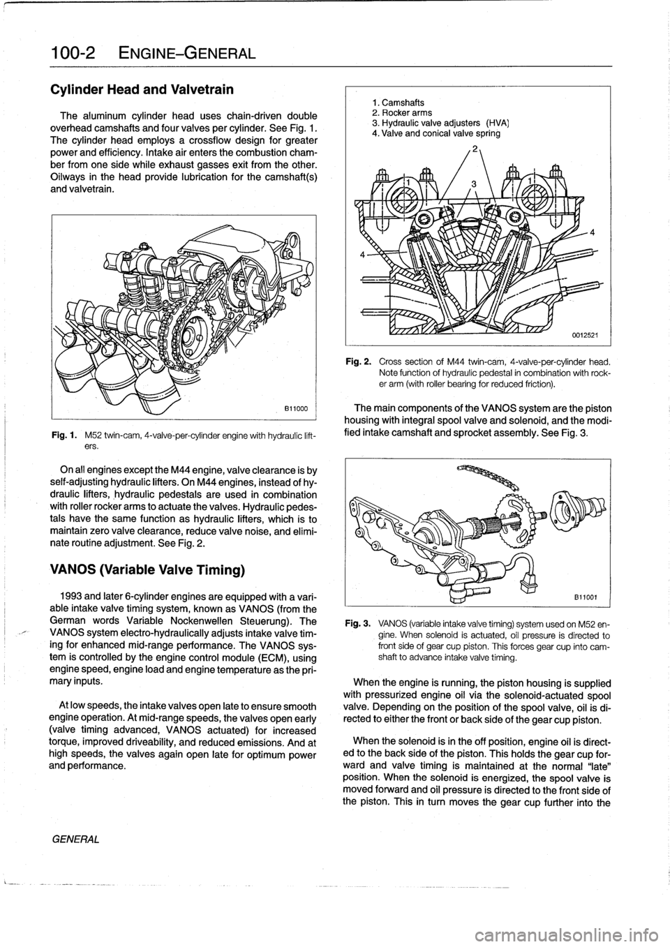
Fig
.
1
.
M52
twin-cam,
4-valve-per-cylinder
engine
with
hydraulíc
lift-
ers
.
On
all
engines
exceptthe
M44
engine,
valveclearance
is
by
seif-adjusting
hydraulic
lifters
.
On
M44
engines,
instead
of
hy-
draulic
lifters,
hydraulic
pedestaisare
used
in
combination
with
roller
rocker
arms
to
actuate
the
valves
.
Hydraulic
pedes-
tals
have
the
same
function
as
hydraulic
lifters,
which
ís
to
maintain
zero
valve
clearance,
reduce
valve
noise,
and
elimí-
nate
routíne
adjustment
.
See
Fig
.
2
.
VANOS
(Variable
Valve
Timing)
GENERAL
1
.
Camshafts
2
.
Rocker
arms
3
.
Hydraulic
valve
adjusters
(HVA)
4
.
Valve
and
conical
valve
spring
4
Fig
.
2
.
Cross
sectionof
M44
twin-cam,
4-valve-per-cylinder
head
.
Note
function
of
hydraulíc
pedestal
in
combination
with
rock-er
arm
(with
roller
bearing
for
reduced
friction)
.
The
main
components
of
the
VANOS
system
arethe
piston
housing
with
integral
spool
valve
and
solenoid,
and
the
modi-
fied
intake
camshaft
and
sprocket
assembly
.
See
Fig
.
3
.
1993
and
later
6-cylinder
engines
are
equipped
with
a
vari-
B11001
able
intake
valve
timing
system,
known
as
VANOS
(from
the
German
words
Variable
Nockenwellen
Steuerung)
.
The
Fig
.
3
.
VANOS
(variable
intake
valve
timing)
systemusedon
M52
en-
VANOS
system
electro-hydraulically
adjusts
intake
valve
tim-
gine
.
When
solenoid
is
actuated,
oíl
pressure
is
directed
to
ingfor
enhanced
mid-range
performance
.
The
VANOS
sys-
front
side
of
gear
cup
piston
.
This
forces
gear
cup
finto
camtem
is
controlled
by
the
engine
control
module
(ECM),
using
shaft
to
advance
intake
valve
timing
.
enginespeed,engine
load
and
engine
temperature
asthe
pri-
mary
inputs
.
When
the
engine
is
running,
the
piston
housing
is
supplied
with
pressurized
engine
oil
víathe
solenoid-actuatedspool
At
low
speeds,
the
intake
valves
open
late
to
ensure
smooth
valve
.
Depending
on
the
position
of
the
spool
valve,
oil
isdi
engine
operation
.
At
mid-rangespeeds,
thevalves
open
early
rected
to
either
the
front
or
back
side
of
the
gear
cup
piston
.
(valvetiming
advanced,
VANOS
actuated)
for
increased
torque,
improved
driveability,
and
reduced
emissions
.
And
at
When
the
solenoid
isin
the
off
position,
engine
oíl
is
direct-
high
speeds,
the
valves
again
open
late
for
optimum
power
ed
to
the
back
side
of
the
piston
.
This
holds
the
gear
cup
for-
and
performance
.
ward
and
valve
timing
is
maintained
at
the
normal
"late"
position
.
When
the
solenoid
is
energized,
the
spoolvalve
is
moved
forward
and
oil
pressure
is
directed
to
the
front
side
of
the
piston
.
This
in
turn
moves
thegear
cup
further
into
the
Page 45 of 759
camshaft
secondary
drive,
causing
thecamshaft
to
"advance"
12
.5°
.
The
helical
gears
are
cut
so
that
forward
motion
of
the
gear
cup
is
transiated
into
rotational
motion
of
the
camshaft
.
See
117
Camshaft
Timing
Chain
for
testing
and
repair
infor-
mation
on
the
VANOS
system
.
DISA
(Dual
Resonance
Intake
System)
DISA,usedon
4-cylinder
engines,
is
a
dual
intake
runner
system
that
effectively
provides
the
advantages
of
both
short
and
long
intake
runners
within
the
same
engine
.
For
best
per-
formance,
long
intake
runners
aremost
beneficial
atlow-
and
mid-engine
speeds
(below
4,200
rpm),
and
short
intake
run-
ners
enhance
torque
at
high
engine
speeds
(above4,200
rpm)
.
NOTE-
The
term
DISA
comes
from
the
German
words
Differ-
enzierte
Sauganlage,
and
can
roughty
be
transiated
as
a
differing
intake
manifold
configuration
.
The
DISA
solenoid
valve
is
controlled
by
the
DME
control
module,
using
engine
speed
as
the
primary
input
.
The
main
components
of
the
system
are
the
modified
twin-section
in-
takemanifoldwith
change-over
valve,
the
twin-barrel
throttle
body,
and
the
electrical/pneumatic
actuating
components
.
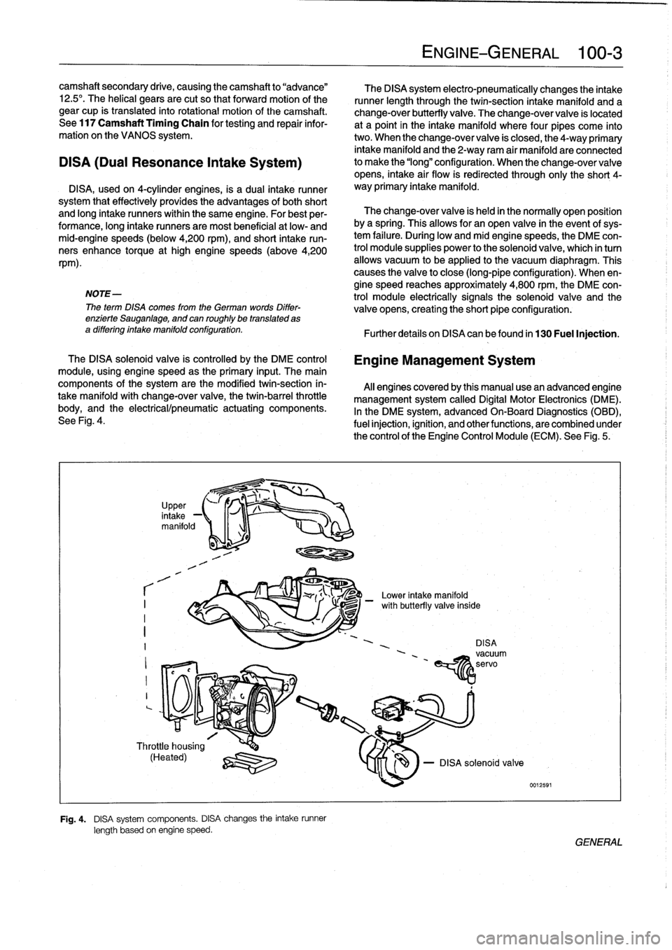
See
Fig
.
4
.
r
I
I
I
?
,
in
UpPer,
take
-1
manifold
1
-1
Throttle
housing
(Heated)
q
:lZU
Fig
.
4
.
DISA
system
components
.
DISA
changes
the
intake
runner
length
based
on
engine
speed
.
The
DISA
system
electro-pneumatically
changes
the
intake
runner
length
through
the
twin-section
intake
manifold
and
a
change-over
butterfly
valve
.
The
change-over
valve
is
located
at
a
point
in
the
intake
manifold
where
four
pipes
come
into
two
.
When
the
change-over
valve
is
closed,
the
4-way
primary
intake
manifold
and
the
2-way
ram
air
manifold
areconnected
to
make
the
"long"
configuration
.
When
the
change-overvalve
opens,
intake
air
flow
is
redirected
through
only
the
short
4-
way
primary
intake
manifold
.
The
change-over
valve
is
held
in
the
normally
open
position
bya
spring
.
Thisallows
for
an
open
valve
in
the
event
of
sys-
tem
failure
.
During
low
andmid
enginespeeds,
the
DME
con-
trol
module
supplies
power
to
the
solenoid
valve,
which
in
turn
allows
vacuum
to
be
applied
lo
the
vacuum
diaphragm
.
This
causes
the
valve
to
close
(long-pipe
configuration)
.
When
en-
gine
speed
reaches
approximately
4,800
rpm,
the
DME
con-
trol
module
electrically
signals
the
solenoid
valve
and
the
valve
opens,
creating
the
short
pipe
configuration
:
Further
detafs
on
DISA
canbefound
in
130
Fuel
Injection
.
Engine
Management
System
Al¡
enginescoveredby
this
manual
usean
advanced
engine
management
system
called
Digital
Motor
Electronics
(DME)
.
In
the
DME
system,
advancedOn-Board
Diagnostics
(OBD),
fuel
injection,
ignition,
and
otherfunctions,
are
combined
under
the
control
of
theEngine
Control
Module
(ECM)
.
See
Fig
.
5
.
-
Lower
intake
manifold
DISAvacuum
'
~servo
EíY1z
ENGINE-GENERAL
100-
3
le
-
DISA
solenoid
valve
0012591
/
with
butterfly
va¡
GENERAL
Page 50 of 759
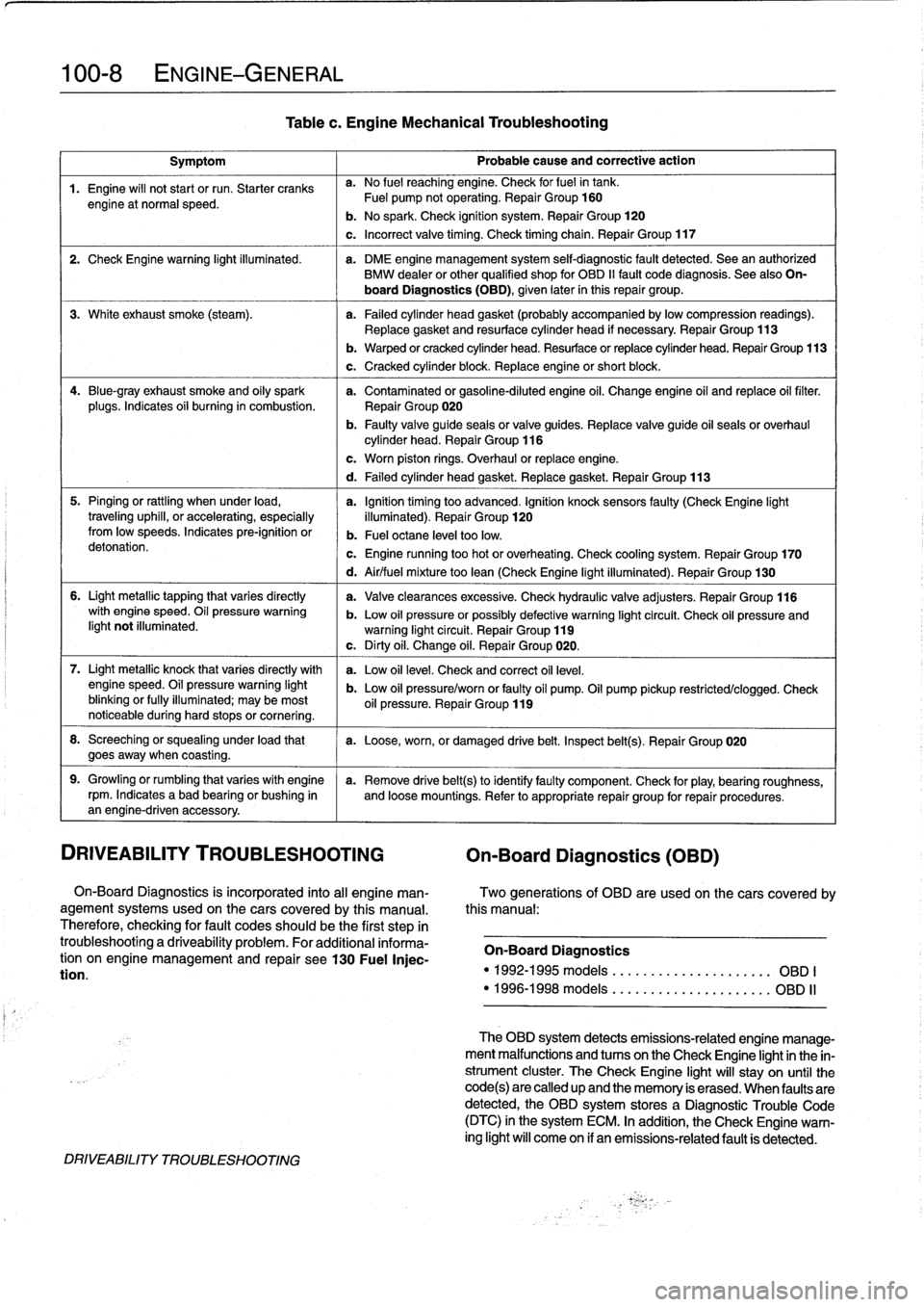
100-8
ENGINE-GENERAL
Symptom
1
Probable
cause
and
correctiveaction
1
.
Engine
will
not
start
or
run
.
Starter
cranks
a
.
No
fuel
reaching
engine
.
Check
forfuelin
tank
.
engine
at
normal
speed
.
Fuel
pump
notoperating
.
Repair
Group
160
b
.
No
spark
.
Check
ignition
system
.
Repair
Group
120
c
.
Incorrect
valve
timing
.
Check
timing
chain
.
Repair
Group
117
2
.
Check
Engine
warning
light
illuminated
.
a
.
DME
engine
management
system
self-diagnostic
fault
detected
.
Sea
an
authorized
BMW
dealer
or
other
qualified
shop
for
OBD
II
fault
code
diagnosis
.
See
also
On-
board
Diagnostics(OBD),
given
later
inthis
repair
group
.
3
.
White
exhaust
smoke
(steam)
.
a
.
Failed
cylinder
head
gasket
(probably
accompanied
bylowcompression
readings)
.
Replace
gasket
and
resurface
cylinder
head
if
necessary
.
Repair
Group
113
4
.
Blue-gray
exhaust
smoke
and
oily
spark
a
.
Contaminated
or
gasoline-diluted
engine
oil
.
Change
engine
oil
and
replace
oil
filter
.
plugs
.
Indicates
oii
burning
in
combustion
.
Repair
Group
020
b
.
Faulty
valve
guide
seals
or
valve
guides
.
Replace
valve
guide
oil
seals
or
overhaul
cylinder
head
.
Repair
Group
116
5
.
Pinging
or
rattling
when
under
load,
a
.
Ignition
timing
too
advanced
.
Ignition
knocksensors
faulty
(CheckEngine
light
traveling
uphill,
or
accelerating,
especially
illuminated)
.
Repair
Group
120fromlow
speeds
.
Indicates
pre-ignition
or
b
.
Fuel
octane
leve¡
toolow
.
detonation
.
c
.
Engine
running
too
hot
or
overheating
.
Check
cooling
system
.
Repair
Group
170
6
.
Light
metallic
tapping
that
varies
directly
with
engine
speed
.
Oil
pressure
warning
light
not
illuminated
.
7
.
Light
metallic
knock
that
varies
directly
with
enginespeed
.
Oil
pressure
warning
light
blinking
or
fully
illuminated
;
may
be
most
noticeable
during
hard
stops
or
cornering
.
8
.
Screeching
or
squealing
under
load
that
a
.
Loose,worn,
or
damaged
drive
belt
.
Inspect
belt(s)
.
Repair
Group
020
goesaway
when
coasting
.
9
.
Growling
or
rumbling
that
varieswith
engine
a
.
Remove
drive
belt(s)toidentifyfaulty
component
.
Check
for
play,
bearing
roughness,
rpm
.
Indicates
abad
bearing
or
bushing
in
and
loose
mountings
.
Refer
to
appropriate
repair
group
for
repair
procedures
.
an
engine-driven
accessory
.
DRIVEABILITY
TROUBLESHOOTING
On-Board
Diagnostics
(OBD)
On-Board
Diagnostics
is
incorporated
into
al¡
engine
man-
Two
generations
of
OBD
are
usedon
thecars
covered
by
agement
systems
used
on
the
cars
covered
by
this
manual
.
this
manual
:
Therefore,
checking
for
fault
codes
should
be
the
first
step
in
troubleshootinga
driveability
problem
.
For
additional
informa-
On-Board
Diagnostics
tion
on
engine
management
and
repair
see130
Fuel
Injec-
tion
.
"
1992-1995models
....
.
..
....
.
..
.......
OBD
I
"
1996-1998models
.
....
..
.
.
.
..
.
........
OBD
II
DRIVEABILITY
TROUBLESHOOTING
Tablec
.
Engine
Mechanical
Troubleshooting
b
.
Warped
or
cracked
cylinder
head
.
Resurface
or
replace
cylinder
head
.
Repair
Group
113
c
.
Cracked
cylinder
block
.
Replace
engine
or
short
block
.
c
.
Worn
piston
rings
.
Overhaul
or
replace
engine
.
d
.
Failed
cylinder
head
gasket
.
Replace
gasket
.
Repair
Group
113
d
.
Air/fuel
mixture
too
lean
(Check
Engine
light
illuminated)
.
Repair
Group
130
a
.
Valveclearances
excessive
.
Check
hydraulic
valve
adjusters
.
Repair
Group
116
b
.
Low
oil
pressure
orpossibly
defective
warning
light
circuit
.
Check
oil
pressure
andwarning
light
circuit
.
Repair
Group
119
c
.
Dirty
oil
.
Change
oil
.
Repair
Group
020
.
a
.
Low
oil
leve¡
.
Check
and
correct
oil
leve¡
.
b
.
Low
oil
pressure/worn
or
faulty
oil
pump
.
Oil
pump
pickup
restricted/clogged
.
Check
oil
pressure
.
Repair
Group
119
The
OBD
system
detects
emissions-related
engine
manage-
ment
malfunctions
and
tucos
on
the
Check
Engíne
lightin
the
in-
strument
cluster
.
TheCheck
Engine
light
will
stay
on
until
the
code(s)are
called
up
and
the
memory
is
erased
.
When
faulty
are
detected,
the
OBD
system
stores
a
Diagnostic
Trouble
Code
(DTC)
in
the
system
ECM
.
In
addition,
the
Check
Engine
warn-
ing
light
will
come
on
if
an
emissions-related
fault
is
detected
.
Page 53 of 759
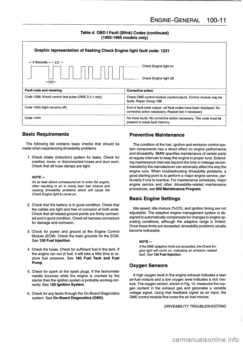
Graphic
representation
of
flashing
Check
Engine
light
fault
code
:
1221
-
;
5
Seconds
.
~-
2
.5;-
Fault
code
and
meaning
Corrective
action
Code
1286
:
Knock
control
test
pulse
(DME
3
.3
.1
only)
Check
DME
control
module
inputs/outputs
.
Control
module
may
be
faulty
Repair
Group
130
Code
1000
(light
remains
off)
:
End
of
fault
code
output-all
fault
codes
have
been
displayed
.
No
~
corrective
action
necessary
.
Repeat
test
if
necessary
Code
1444
:
No
more
faults
.
No
corrective
action
necessary
.
This
code
must
be
present
lo
erase
fault
memory
Basic
Requirements
Preventive
Maintenance
The
following
list
contains
basic
checks
that
should
be
made
when
experiencing
driveability
problems
.
1
.
Check
intake
(induction)
system
for
leaks
.
Check
for
cracked,
loose,
or
disconnected
hoses
and
duct
work
.
Check
that
all
hose
clamps
are
tight
.
NOTE-
An
air
leak
allows
unmeasured
airto
enter
the
engine,
offen
resulting
in
an
in
overly
lean
fuel
mixture
and
causing
driveability
problems
which
will
cause
the
Check
Engine
light
to
come
on
.
Table
d
.
OBD
I
Fault
(Blink)
Codes
(continued)
(1992-1995
models
only)
7
-
1
--------------
Check
Engine
light
on
ENGINE-GENERAL
100-
1
1
Check
Engine
light
off
The
condition
of
the
fuel,
ignition
and
emission
controlsys-
tem
components
has
a
directeffect
onengineperformance
and
driveability
.
BMW
specifies
maintenance
of
certain
parts
at
regular
intervals
lo
keep
the
engine
in
proper
tune
.
Extend-
ing
maintenance
intervals
beyond
the
time
or
mileagerecom-
mended
bythe
manufacturer
can
adversely
affect
the
way
the
engine
runs
.
When
troubleshooting
driveability
problems,
a
good
starting
point
is
to
perform
a
major
engine
service,par-
ticularly
if
one
is
overdue
.
For
maintenance
schedules,
major
engine
service
and
other
driveability-related
maintenance
procedures,
see020
Maintenance
Program
.
Basic
Engine
Settings
2
.
Check
that
the
battery
isin
good
condition
.
Check
that
the
cables
are
tight
and
free
of
corrosion
at
both
ends
.
Idle
speed,
idle
mixture
(%CO),
and
ignition
timing
are
not
Check
that
all
related
ground
points
are
firmly
connect-
adjustable
.
The
adaptive
engine
management
system
is
de-
ed
and
in
good
condition
.
Check
al¡
harness
connectors
signed
lo
automatically
compensate
for
changes
in
engine
op-
for
damage
and
corrosion
.
erating
conditions,
although
the
adaptive
range
is
limited
.
Once
these
limits
are
exceeded,
driveability
problems
usually
3
.
Check
for
prwer
and
ground
at
the
Engine
Control
become
noticeable
.
Module
(ECM)
.
Check
the
main
grounds
for
the
ECM
.
See130
Fuel
Injection
.
NOTE-
If
the
DME
adaptive
limits
are
exceeded,
the
Check
En-
4
.
Check
the
fuses
.
Check
for
sufficient
fuel
in
the
tank
.
If
gine
light
will
come
on,
indicating
an
emission
related
the
engine
ranout
of
fuel,
it
will
take
a
little
time
to
re-
fault
.
See
130
Fuel
Injection,
store
fuel
pressure
.
See
160
Fuel
Tank
and
Fuel
Pump
.
Oxygen
Sensors
5
.
Check
for
spark
at
the
spark
plugs
.
If
the
tachometer
needle
bounces
while
the
engine
is
crankedby
the
A
high
oxygen
level
in
the
engine
exhaust
indicates
a
lean
starter
then
the
ignition
system
is
probably
working
cor-
air-fuel
mixture
and
a
low
oxygen
level
indicates
a
rich
mix
rectly
.
See
120
Ignition
System
.
ture
.
The
oxygen
sensor,
shown
in
Fig
.
10,
measures
the
oxy-
gen
content
in
the
exhaust
gasand
generates
a
variable
6
.
Check
for
any
faults
through
the
On-Board
Diagnostics
voltage
signal
.
Using
that
feedback
signal
asan
input,
the
system
.
See
On-Board
Diagnostics
(OBD)
.
DME
control
module
fine
tunes
the
air-fuel
mixture
.
DRIVEABILITY
TROUBLESHOOTING
Page 62 of 759
110-
4
ENGINE
REMOVAL
AND
INSTALLATION
Engine,
removing
and
installing
(6-cylinder
engines)
Engineremoval
procedures
for
the
various
6-cylinder
en-
gines
arecovered
in
this
section
.
Most
steps
in
theproce-
dures
are
similar
or
the
same
for
al¡
engines
.
Specific
differences
that
apply
are
noted
at
the
beginning
of
each
step
.
Be
sure
to
cover
all
painted
surfaces
before
beginning
the
removal
procedure
.
As
an
aid
to
installation,
label
all
compo-
nents,wires,
and
hoses
before
removing
them
.
Do
not
reuse
gaskets,
O-rings
or
seals
during
reassembly
.
WARNING
-
Due
to
risk
of
personal
injury,
be
sure
the
engine
is
cold
before
beginning
the
removalprocedure
.
1
.
Disconnect
negative
(-)
battery
cable
in
luggage
com-
partment
.
CAUTION-
Prior
to
disconnecting
the
battery,
read
the
battery
disconnection
cautions
given
at
the
front
of
this
manual
onpage
vi¡¡
.
2
.
Remove
engine
hood
or
place
hood
in
service
position
.
See410
Fenders,
Engine
Hood
.
NOTE-
1t
is
not
necessary
to
remove
the
engine
hood,
but
it
is
helpful
and
will
make
engine
removal
and
installation
easier
.
3
.
Remove
splash
guardunder
engine,
if
applicable
.
4
.
Remove
transmission
from
car
.
See
230
Manual
Transmission
or
240Automatic
Transmission
.
5
.
Remove
vacuum
hosefrom
brake
booster
on
bulkhead
.
Cover
hole
in
booster
and
plug
hose
end
.
6
.
Remove
intake
air
plenum
panel
in
rear
of
engine
com-
partment
.
See
640
Heating
and
AirConditioning
.
7
.
Remove
ground
strap
from
timing
case
cover,
if
appli-
cable
.
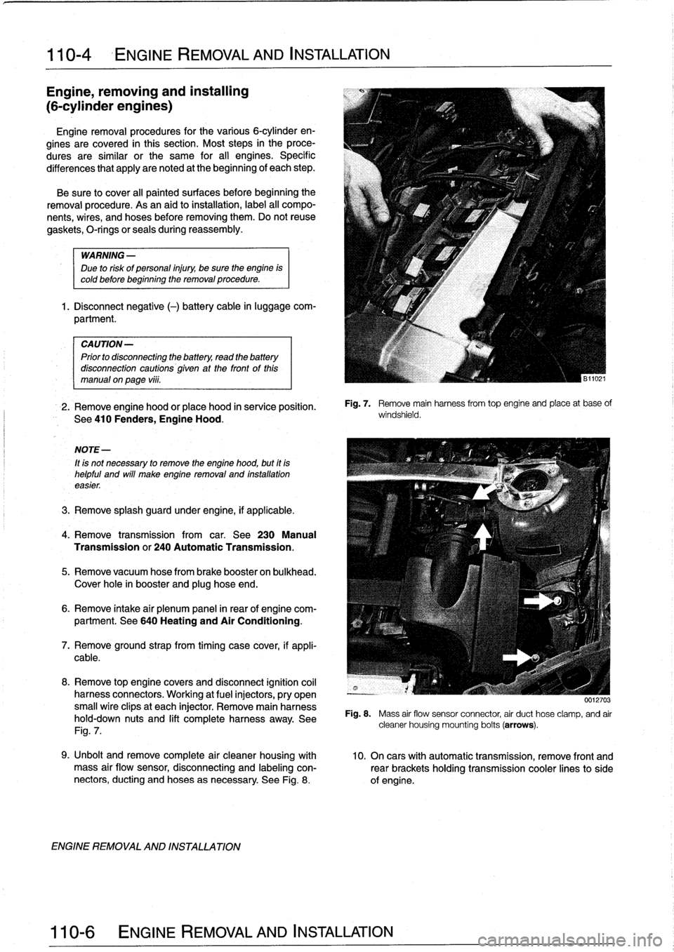
8
.
Remove
top
enginecovers
and
disconnect
ignition
coil
harness
connectors
.
Working
at
fuel
injectors,
pry
open
small
wire
clipsat
each
injector
.
Remove
main
harness
hold-down
nuts
and
lift
completeharness
away
.
See
Fig
.
7
.
ENGINE
REMOVAL
AND
INSTALLATION
Fig
.
7
.
Remove
mainharnessfrom
top
engine
and
place
at
base
of
windshield
.
0012703
Fig
.
8
.
Mass
air
flow
sensor
connector
air
duct
hose
clamp,
and
air
cleaner
housing
mounting
bolts
(arrows)
.
9
.
Unbolt
andremove
complete
air
cleaner
housing
with
10
.
On
cars
with
automatic
transmission,
remove
front
and
mass
air
flow
sensor,
disconnecting
and
labeling
con-
rearbrackets
holding
transmission
cooler
linesto
side
nectors,
ducting
and
hoses
asnecessary
.
See
Fig
.
8
.
of
engine
.
Page 67 of 759
113
Cylinder
Head
Removal
and
Installation
GENERAL
.
...............
.
.
.
.
.
.......
113-1
CYLINDER
HEAD,
6-CYLINDER
.
.
.
.
.
.
.
113-10
Cylinder
head,
removing
(6-cylinder
engine)
..
113-10
CYLINDER
HEAD,
4-CYLINDER
..
.
...
.
.
113-1
Cylinder
head,
installing
(6-cylinder
engine)
...
113-15
Cylinder
head,
removing
(4-cylinder
engine)
...
113-1
E
Cylinder
head,
installing
(4-cylinder
engine)
...
113-6
GENERAL
CYLINDER
HEAD,
4-CYLINDER
The
information
given
inthis
repair
group
assumes
that
the
engine
is
installed
in
the
engine
bay
.
For
cylinder
head,
cam-
Cylinder
head,
removing
shaft,
and
valvetrain
disassembly
and
reconditioning
informa-
(4-cylinder
engine)
tion,
see116
Cylinder
Head
and
Valvetrain
.
For
ease
of
use
this
removal
procedure
is
broken
into
sub-
In
the
procedures
given
below,
engines
are
referred
to
by
sections,
as
follows
:
engine
code
.
If
necessary,
see100
Engine-General
for
en-
gine
code
and
application
information
.
NOTE-
If
a
head
gasket
problem
is
suspected,
acompression
test
will
usually
detectthe
fault
.
See
100
Engine-Gen-
eral
for
compression
testing
information
.
Special
BMW
service
tools
are
required
to
properly
remove
and
install
the
cylinder
head
on
both
the
4-cylinder
and
6-cyl-
inder
engines
.
The
special
tools
are
used
to
time
the
val-
vetrain
to
the
crankshaft
and
to
remove
the
Torx
(El
2)
head
bolts
.
Read
the
procedure
through
before
beginning
thejob
.
Cover
al¡
painted
surfaces
before
beginning
the
removal
procedure
.
As
an
aid
to
installation,
label
all
components,
wires,
and
hoses
before
removing
them
.
Do
not
reuse
gas-
kets,
O-rings
or
seals
during
reassembly
.
WARNING
-
Due
to
risk
of
personal
injury,
be
sure
the
engine
is
cold
before
beginning
the
removalprocedure
.
CYLINDER
HEAD
REMOVAL
AND
INSTALLATION
113-1
General
Coolingsystem,
draining
Cylinder
head
cover,
removing
Intake
manifold,
removing
Timing
chains,
uncoupling
Cylinder
head
assembly,
removing
WARNING
-
Allow
engine
to
cool
before
beginning
this
proce-
dure
.
General
1
.
Disconnect
negative
(-)
cable
from
battery
.
CAUTION
-
"
Prior
to
disconnectiog
the
battery,
read
the
bat-
tery
disconnection
cautions
given
at
the
front
of
this
manual
on
page
viii
.
"
Disconnecting
the
battery
may
erase
fault
codees)
stored
in
control
module
memory
.
Check
for
fault
codes
using
special
BMW
diagnostic
equipment
.
NOTE-
The
battery
is
mounted
in
the
luggage
compartment
behind
the
right
side
trim
panel
.
2
.
Working
underneath
vehicle,
remove
front
exhaust
pipe
from
exhaust
manifold
.
See
Fig
.
1
.
3
.
Disconnect
vacuum
hose
fitting
from
brake
booster
on
rear
bulkhead
.
Plug
opening
in
booster
and
hose
end
.
CYLINDER
HEAD,
4-CYLINDER
Page 70 of 759
113-4
CYLINDER
HEAD
REMOVAL
AND
INSTALLATION
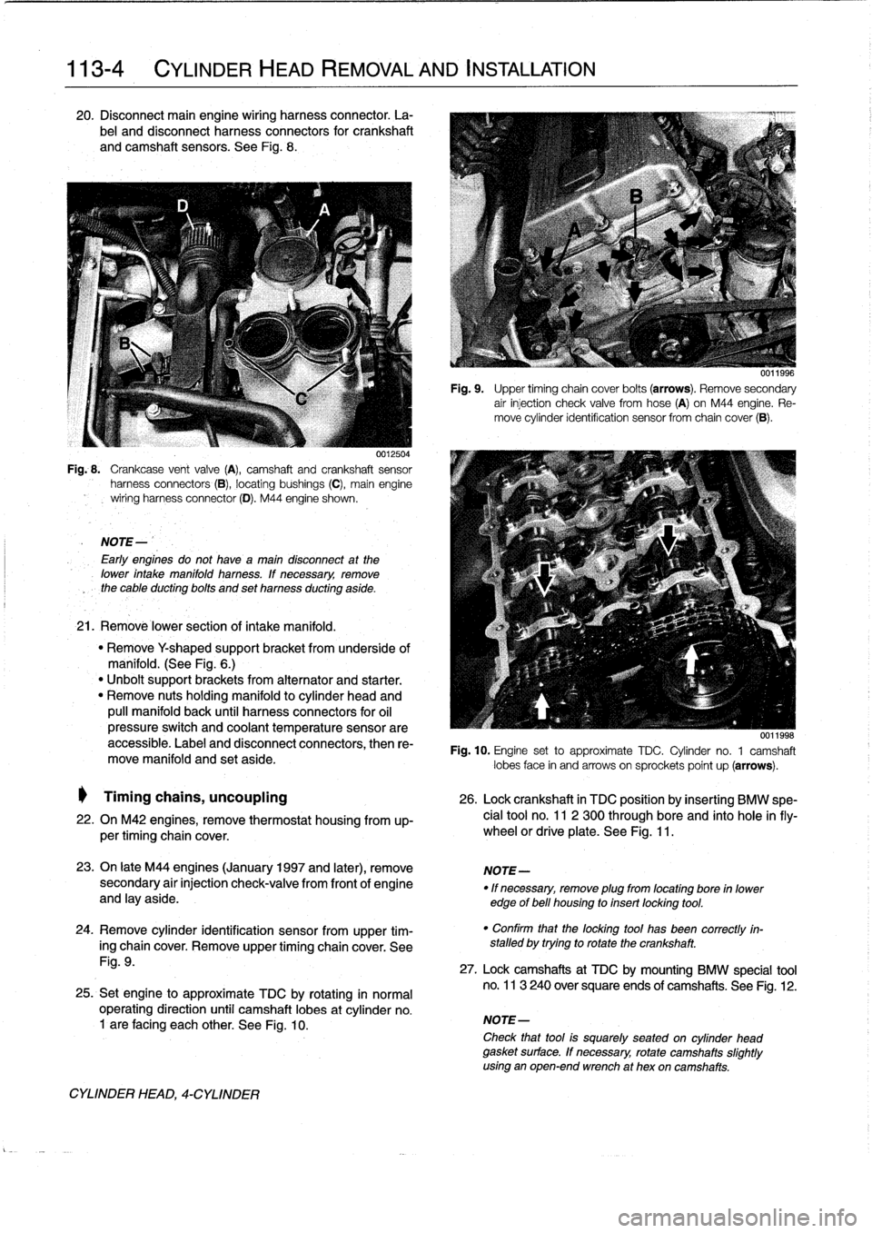
20
.
Disconnect
main
engine
wiring
harness
connector
.
La-
bel
and
disconnect
harness
connectors
for
crankshaft
and
camshaft
sensors
.
See
Fig
.
8
.
0012504
Fig
..
Crankcase
vent
valve
(A),
camshaft
and
crankshaft
sensor
harness
connectors
(B),
locating
bushings
(C),
main
engine
wiring
harnessconnector
(D)
.
M44
engine
shown
.
NOTE-
Early
engines
do
not
havea
maín
disconnect
at
the
lower
intake
manifold
harness
.
lf
necessary,
remove
the
cable
ducting
bolts
and
set
harness
ducting
aside
.
21
.
Remové
lower
section
of
intake
manifold
.
"
Remove
Y
shaped
supportbracket
from
underside
of
manifold
.
(See
Fig
.
6
.)
"
Unbolt
support
brackets
from
alternator
and
starter
.
"
Remove
nuts
holding
manifold
to
cylinder
head
and
pull
manifold
back
until
harness
connectors
for
oil
pressure
switch
and
coolant
temperature
sensorare
accessible
.
Label
and
disconnect
connectors,
then
re-
move
manifold
and
set
aside
.
Timing
chains,
uncoupling
26
.
Lock
crankshaft
in
TDC
position
by
insertíng
BMW
spe-
22
.
On
M42
engines,
remove
thermostat
housing
from
up-
cial
tool
no
.
11
2
300
through
bore
and
into
hole
infly-
per
timing
chaincover
.
wheel
or
driveplate
.
See
Fig
.
11
.
23
.
On
late
M44
engines
(January
1997
and
later),
remove
NOTE-
secondary
air
injection
check-valve
from
front
of
engine
"
If
necessary,
remove
plug
from
locating
bore
in
lower
and
lay
aside
.
edge
of
bell
housing
to
insert
locking
tool
.
24
.
Remove
cylinder
identification
sensor
from
upper
tim-
ing
chaincover
.
Remove
upper
timing
chaincover
.
See
Fig
.
9
.
25
.
Set
engine
to
approximate
TDC
by
rotating
in
normal
operating
direction
until
camshaft
lobes
at
cylinder
no
.
1
are
facing
each
other
.
See
Fig
.
10
.
CYLINDER
HEAD,
4-CYLINDER
Fig
.
9
.
Upper
timing
chain
cover
bolts
(arrows)
.
Remove
secondary
air
injection
check
valve
fromhose
(A)
on
M44
engine
.
Re-
move
cylinder
identification
sensor
from
chaincover
(B)
.
0011998
Fig
.
10
.
Engine
set
to
approximate
TDC
.
Cylinder
no
.
1
camshaft
lobes
face
in
and
arrows
on
sprockets
poínt
up
(arrows)
.
"
Confirm
that
the
locking
tool
has
been
correctly
in-
stalled
by
trying
to
rotate
the
crankshaft
.
27
.
Lock
camshafts
at
TDC
by
mounting
BMW
specíal
tool
no
.
113
240
over
square
ends
of
camshafts
.
See
Fig
.
12
.
NOTE-
Check
that
tool
is
squarely
seated
on
cylinder
head
gasket
surface
.
If
necessary,
rotate
camshafts
slightly
using
an
open-end
wrench
at
hex
oncamshafts
.
Page 71 of 759
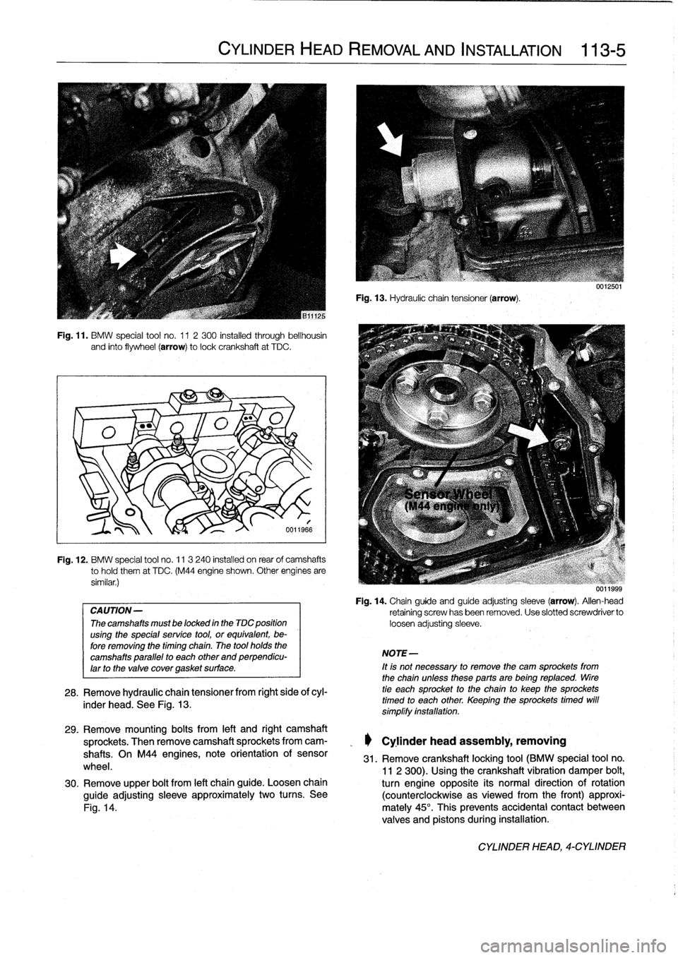
Fig
.
11
.
BMW
special
tool
no
.
11
2300
installed
through
bellhousin
and
finto
flywheel
(arrow)
tolockcrankshaft
at
TDC
.
Fig
.
12
.
BMW
special
tool
no
.
11
3
240
installed
on
rear
of
camshafts
tohold
them
at
TDC
.
(M44
engine
shown
.
Other
engínes
are
similar
.)
CAUTION-
The
camshafts
must
be
locked
in
the
TDC
position
using
the
special
service
tool,
or
equivalent,
be-
fore
removing
the
timing
chaín
.
The
tool
holds
the
camshafts
parallel
to
each
other
and
perpendicu-
larto
the
valve
covergasket
surface
.
CYLINDER
HEAD
REMOVAL
AND
INSTALLATION
113-5
6011966
28
.
Remove
hydraulic
chain
tensiones
from
right
side
ofcyl-
inder
head
.
See
Fig
.
13
.
Fig
.
13
.
Hydraulic
chain
tensioner
(arrow)
.
NOTE-
It
is
not
necessary
to
remove
the
cam
sprockets
from
the
chainuntessthese
parts
are
being
reptaced
.
tire
tie
each
sprocket
to
the
chain
to
keep
the
sprockets
timed
to
each
other
.
Keeping
the
sprockets
timed
will
símplífy
instaftation
.
uu
11999
Fig
.
14
.
Chainguide
and
guide
adjusting
sleeve
(arrow)
.
Allen-head
retaining
screwhasbeen
removed
.
Use
slotted
screwdriver
to
loosen
adjusting
sleeve
.
29
.
Remove
mounting
bolts
from
left
and
right
camshaft
sprockets
.
Then
remove
camshaft
sprockets
from
cam-
_
Cylinder
head
assembly,
removing
shafts
.
On
M44
engines,
note
orientation
of
sensor
31
.
Remove
crankshaft
locking
tool
(BMW
special
tool
no
.
wheel
.
11
2
300)
.
Usingthe
crankshaft
vibration
damper
bolt,
30
.
Remove
upper
bolt
from
left
chainguide
.
Loosen
chain
turn
engine
opposite
its
normal
direction
of
rotation
guide
adjusting
sleeve
approximately
two
turns
.
See
(counterclockwise
asviewed
from
the
front)
approxi
Fig
.
14
.
mately
45°
.
This
prevents
accidental
contact
between
valves
and
pistons
during
installation
.
CYLINDER
HEAD,
4-CYLINDER