coolant temp sensor BMW M3 1998 E36 Workshop Manual
[x] Cancel search | Manufacturer: BMW, Model Year: 1998, Model line: M3, Model: BMW M3 1998 E36Pages: 759
Page 46 of 759
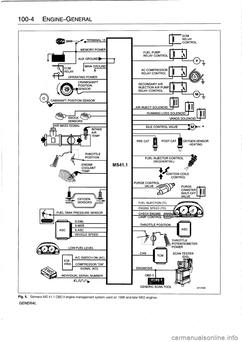
100-4
ENGINE-GENERAL
'
TEMP
PRECAT
POST
CAT
OXYGENSENSOR
HEATING
#
.
THROTTLE
POSITION
FUEL
INJECTOR
CONTROL
(SEQUENTIAL)
OPERATING
POWER
00
CAMSHAFT
POSITION
SENSOR
ECM
I
MAIN
GROUND
RELAY
J_
-
AC
COMPRESSOR
RELAY
CONTROL
TERMINAL
15
MEMORY
POWER
FUEL
PUMP
RELAY
CONTROL
AUX
GROUND
P
CRANKSHAFT
POSITION
dESENSOR
INTAKE
AIR
ENGINE
COOLANT
TEMP
FUEL
TANK
PRESSURE
SENSOR
S-EML
S-MSR
ASC
S-ASC
VEHICLE
SPEED
LOW
FUEL
LEVEL
A/C
SWITCH
ON
(AC)
E36
IHKA
COMPRESSOR"ON"
SIGNAL
(KO)
INDIVIDUAL
SERIAL
NUMBER
MS41
.1
SECONDARY
AIR
1NJECTION
AIR
PUMP®
RELAY
CONTROL
IDLE
CONTROL
VALVE
'M
FUEL
INJECTION
(TI)
ENGINE
SPEED
(TD)
Fig
.
5
.
Siemens
MS
41
.1
OBD
II
engine
management
systemusedon
1996
and
later
M52
engines
.
GENERAL
IGNITION
COILS
CONTROL
L
r"Q
if~
CIYVFIYC
CHE
AMP
CONTROL
ENGINE
THROTTLE
POSITION
6
ECM
RELAY
CONTROL
ASC
THROTTLE
..
:
.
.
..
-11
1Q\\\
POTENTIOMETER
POWER
CAN
TCM
II
SCAN
(DES
;
ER
DIAGNOSIS
OBD
II
I
II
GENERIC
SCANTOOL
0012596
Page 51 of 759
NOTE-
"
On
carswith
OBD
ti,
specialized
OBD
11
scan
tool
equipment
must
be
used
to
access
the
DTCs,
either
using
the
BMW
special
tool
ora
`generic"
OBD
11
scan
tool
.
See
130
Fuel
Injection
.
"
The
08D
11
fault
memory
(including
an
iiluminated
Check
Engine
light)
can
only
be
reset
using
the
spe-
cial
scan
tool
.
Removing
the
connector
from
the
ECM
or
disconnecting
the
battery
will
not
erase
the
fault
memory
.
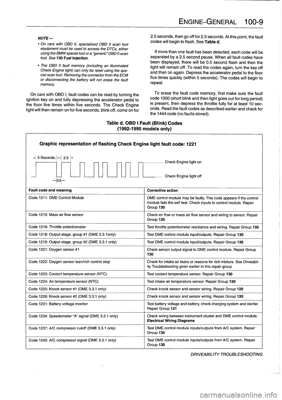
Table
d
.
OBD
1
Fault
(Blink)
Codes
(1992-1995
modeis
only)
Graphic
representation
of
flashing
Check
Engine
light
fault
code
:
1221
5
Seconds
.
:-
2
.5~-
--05--
Fault
code
and
meaning
1
Corrective
action
Code
1216
:
Throttle
potentiometer
Code
1218
:
Output
stage,
group#1
(DME
3
.3
.ionly)
Code
1219
:
Output
stage,
group
#2
(DME
3
.3.1
only)
Code
1221
:
Oxygen
sensor
#1
Code
1224
:
Air
temperature
sensor
(NTC)
Code
1226
:
Knock
sensor
#2
(DME
3
.3
.1
only)
130
ENGINE-GENERAL
100-
9
2
.5
seconds,
then
go
off
for
2
.5
seconds
.
At
thispoint,
the
fault
codes
will
begin
to
flash
.
See
Table
d
.
If
more
than
one
fault
has
been
detected,
eachcode
will
be
separated
by
a2
.5
second
pause
.
When
al¡
fault
codes
havebeen
displayed,
there
will
be0
.5
second
flash
and
thenthe
light
will
remain
off
.
To
read
the
codes
again,
turn
the
key
off
and
then
on
again
.
Depress
theaccelerator
pedal
to
the
floor
five
times
quickly
(within
5
seconds)
.
The
codes
will
begin
to
repeat
.
On
cars
with
OBD
I,
fault
codes
can
be
read
by
turning
the
To
erase
the
fault
code
memory,
first
make
sure
the
fault
ignition
key
on
and
fully
depressing
theaccelerator
pedal
to
code
1000
(short
blink
and
then
light
goes
out
for
long
period)
the
floor
five
times
within
five
seconds
.
TheCheck
Engine
is
present,
then
depress
the
throttle
fully
for
at
least
10
sec-
light
will
then
remain
on
for
five
seconds,
blink
off,
come
on
for
onds
.
Read
the
fault
codes
as
described
earlier
and
check
for
the
1444
code
(no
faults
stored)
.
-,--------------
Check
Engine
light
on
Check
Engine
light
off
Code
1211
:
DM
E
Control
Module
DME
control
module
may
be
faulty
.
This
code
appears
if
the
control
module
fails
the
self
test
.
Check
inputsto
control
module
.
Repair
Group
130
Code
1215
:
Mass
air
flow
sensor
Check
air
flow
or
mass
air
flow
sensor
and
wiring
to
sensor
.
Repair
Group
130
Test
throttle
potentiometer
resistance
and
wiring
.
Repair
Group
130
Test
DME
control
module
input/outputs
.
Repair
Group
130
Test
DME
control
module
input/outputs
.
Repair
Group
130
Check
sensor
output
signal
to
DME
control
module
.
Repair
Group
Code
1222
:
Oxygen
sensor
lean/rich
control
stop
Check
for
intake
air
leaks
or
reasons
forrich
míxture
.
See
Driveabil-
ity
Troubleshooting
given
earlier
in
this
repair
group
Code
1223
:
Coolant
temperaturesensor
(NTC)
1
Test
coolant
temperature
sensor
.
Repair
Group
130
Test
intake
air
temperature
sensor
.
Repair
Group
130
Code
1225
:
Knock
sensor#1
(DME
3
.3
.1
only)
1
Check
knocksensorand
sensor
wiring
.
Repair
Group
120
Check
knocksensor
and
sensor
wiring
.
Repair
Group
120
Code
1231
:
Batteryvoltage
monitor
Test
battery
voltage
and
battery
check
charging
system
and
starter
.
Repair
Group
121
Code
1234
:
Speedometer
"A"signal
(DME
3
.3
.1
only)
Check
wiring
between
instrument
cluster
and
DME
control
module
.
Electrical
Wiring
Diagrams
Code
1237
:
A/C
compressor
cutoff
(DME
3
.3
.1
only)
Test
DME
control
module
inputs/outputs
from
A/C
system
.
Repair
Group
130
Code
1242
:
A/C
compressor
signal
(DME
3
.3.1
only)
Test
DME
control
module
inputs/outputs
from
A/C
system
.
Repair
Group
130
DRIVEABILITY
TROLIBLESHOOTING
Page 70 of 759
113-4
CYLINDER
HEAD
REMOVAL
AND
INSTALLATION
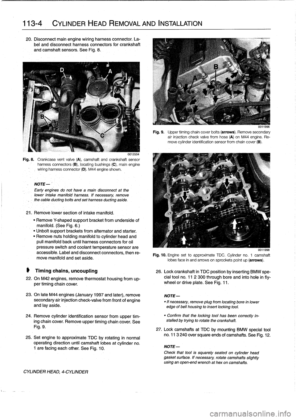
20
.
Disconnect
main
engine
wiring
harness
connector
.
La-
bel
and
disconnect
harness
connectors
for
crankshaft
and
camshaft
sensors
.
See
Fig
.
8
.
0012504
Fig
..
Crankcase
vent
valve
(A),
camshaft
and
crankshaft
sensor
harness
connectors
(B),
locating
bushings
(C),
main
engine
wiring
harnessconnector
(D)
.
M44
engine
shown
.
NOTE-
Early
engines
do
not
havea
maín
disconnect
at
the
lower
intake
manifold
harness
.
lf
necessary,
remove
the
cable
ducting
bolts
and
set
harness
ducting
aside
.
21
.
Remové
lower
section
of
intake
manifold
.
"
Remove
Y
shaped
supportbracket
from
underside
of
manifold
.
(See
Fig
.
6
.)
"
Unbolt
support
brackets
from
alternator
and
starter
.
"
Remove
nuts
holding
manifold
to
cylinder
head
and
pull
manifold
back
until
harness
connectors
for
oil
pressure
switch
and
coolant
temperature
sensorare
accessible
.
Label
and
disconnect
connectors,
then
re-
move
manifold
and
set
aside
.
Timing
chains,
uncoupling
26
.
Lock
crankshaft
in
TDC
position
by
insertíng
BMW
spe-
22
.
On
M42
engines,
remove
thermostat
housing
from
up-
cial
tool
no
.
11
2
300
through
bore
and
into
hole
infly-
per
timing
chaincover
.
wheel
or
driveplate
.
See
Fig
.
11
.
23
.
On
late
M44
engines
(January
1997
and
later),
remove
NOTE-
secondary
air
injection
check-valve
from
front
of
engine
"
If
necessary,
remove
plug
from
locating
bore
in
lower
and
lay
aside
.
edge
of
bell
housing
to
insert
locking
tool
.
24
.
Remove
cylinder
identification
sensor
from
upper
tim-
ing
chaincover
.
Remove
upper
timing
chaincover
.
See
Fig
.
9
.
25
.
Set
engine
to
approximate
TDC
by
rotating
in
normal
operating
direction
until
camshaft
lobes
at
cylinder
no
.
1
are
facing
each
other
.
See
Fig
.
10
.
CYLINDER
HEAD,
4-CYLINDER
Fig
.
9
.
Upper
timing
chain
cover
bolts
(arrows)
.
Remove
secondary
air
injection
check
valve
fromhose
(A)
on
M44
engine
.
Re-
move
cylinder
identification
sensor
from
chaincover
(B)
.
0011998
Fig
.
10
.
Engine
set
to
approximate
TDC
.
Cylinder
no
.
1
camshaft
lobes
face
in
and
arrows
on
sprockets
poínt
up
(arrows)
.
"
Confirm
that
the
locking
tool
has
been
correctly
in-
stalled
by
trying
to
rotate
the
crankshaft
.
27
.
Lock
camshafts
at
TDC
by
mounting
BMW
specíal
tool
no
.
113
240
over
square
ends
of
camshafts
.
See
Fig
.
12
.
NOTE-
Check
that
tool
is
squarely
seated
on
cylinder
head
gasket
surface
.
If
necessary,
rotate
camshafts
slightly
using
an
open-end
wrench
at
hex
oncamshafts
.
Page 75 of 759
Fig
.
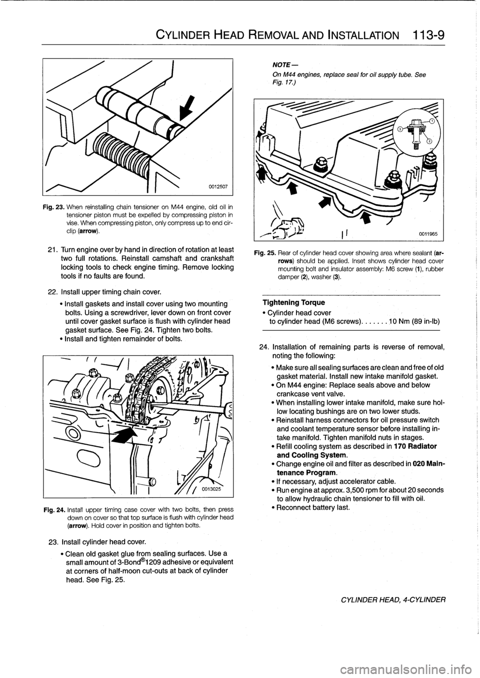
23
.
When
reinstalling
chain
tensioner
on
M44
engine,
old
oil
in
tensioner
piston
mustbe
expelled
bycompressing
piston
in
vise
.
When
compressing
piston,
only
compress
up
to
end
cir-
clip
(arrow)
.
21
.
Turn
engine
overby
hand
in
direction
of
rotation
at
least
two
fui¡
rotations
.
Reinstall
camshaft
and
crankshaft
locking
tools
to
check
engíne
timing
.
Remove
locking
tools
if
no
faults
are
found
.
22
.
Insta¡¡
upper
timingchain
cover
.
"
Install
gaskets
and
instan
cover
using
two
mounting
Tightening
Torque
bolts
.
Using
a
screwdriver,
lever
down
on
front
cover
"
Cylinder
head
cover
until
cover
gasket
surface
is
flush
with
cylinder
head
to
cylinder
head
(M6
screws)
.......
10
Nm
(89
in-lb)
gasket
surface
.
See
Fig
.
24
.
Tighten
two
bolis
.
"
Insta¡¡
and
tighten
remainder
of
bolis
.
23
.
Install
cylinder
head
cover
.
CYLINDER
HEAD
REMOVAL
AND
INSTALLATION
113-
9
0012507
Fig
.
24
.
Install
upper
timing
case
cover
with
two
bolis,
then
press
down
on
cover
so
that
top
surface
is
flush
withcylinder
head
(arrow)
.
Hold
cover
in
position
and
tighten
bolis
.
"
Clean
old
gasket
glue
from
sealing
surfaces
.
Usea
small
amount
of
3-Bond
®
1209
adhesive
or
equivalent
at
corners
of
half-moon
cut-outs
at
back
of
cylinder
head
.
See
Fig
.
25
.
NOTE-
OnM44
engines,
reptace
sea¡
for
oil
supply
tube
.
See
Fig
.
17
.)
Fig
.
25
.
Rear
of
cylinder
head
cover
showing
area
where
sealant
(ar-
rows)
should
be
applied
.
Inset
shows
cylinder
head
cover
mounting
bolt
and
insulator
assembly
:
M6
screw
(1),
rubber
damper
(2),
washer
(3)
.
24
.
Installation
of
remaining
parts
is
reverseofremoval,
noting
the
following
:
"
Make
sure
al¡
sealing
surfaces
are
clean
and
free
of
old
gasket
material
.
Install
new
intake
manifold
gasket
.
"
On
M44
engine
:
Replace
seals
above
and
below
crankcase
ventvalve
.
"
When
installing
lower
intake
manifold,
make
sure
hol-
low
locating
bushings
are
on
two
lower
studs
.
"
Reinstall
harness
connectors
for
oil
pressure
switch
and
coolant
temperature
sensor
before
installing
in-
take
manifold
.
Tighten
manifold
nuts
in
stages
.
"
Refill
cooling
system
as
described
in
170
Radiator
and
Cooling
System
.
"
Change
engine
oil
and
filter
as
described
in
020
Main-
tenance
Program
.
"
If
necessary,
adjust
accelerator
cable
.
"
Run
engine
at
approx
.
3,500
rpm
for
about
20
seconds
to
allow
hydraulic
chain
tensioner
to
fill
with
oil
.
"
Reconnect
battery
last
.
CYLINDER
HEAD,-CYLINDER
Page 84 of 759
113-
1
8
CYLINDER
HEAD
REMOVAL
AND
INSTALLATION
CYLINDER
HEAD,
6-CYLINDER
Fig
.
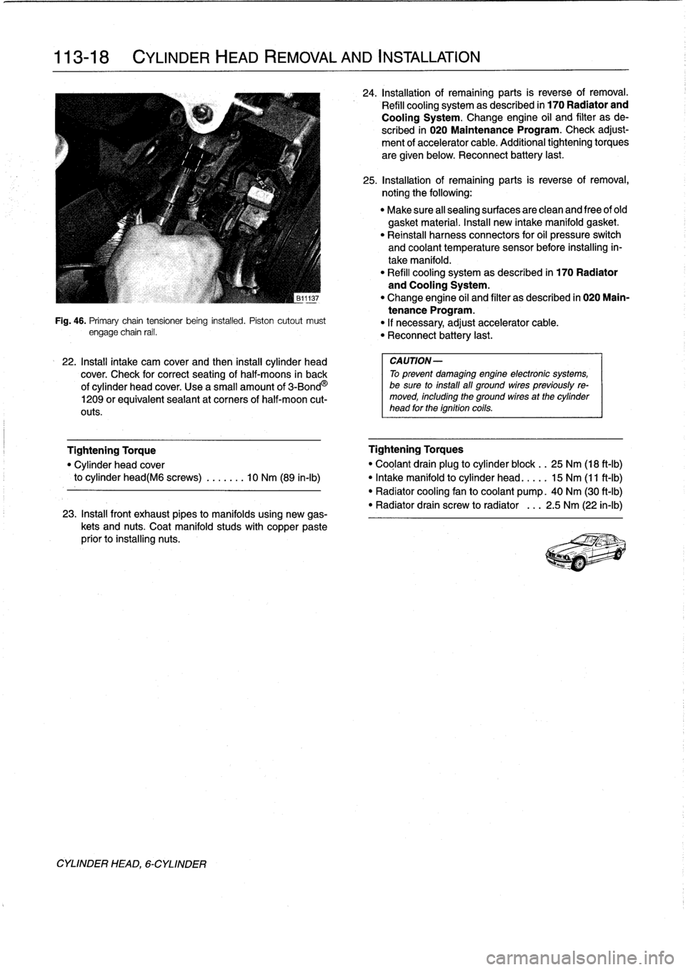
46
.
Primary
chaintensioner
being
installed
.
Piston
cutout
must
engage
chain
rail
.
22
.
Install
intake
cam
cover
and
then
install
cylinder
head
cover
.
Check
for
correct
seating
of
half-moons
in
back
of
cylinder
head
cover
.
Use
a
small
amount
of
3-Bond
O
1209
orequivalent
seaiant
at
corners
of
half-moon
cut-
outs
.
23
.
Install
front
exhaust
pipes
to
manifolds
using
new
gas-
kets
and
nuts
.
Coat
manifold
studs
with
copper
paste
prior
to
installing
nuts
.
24
.
Installationof
remaining
parts
is
reverse
of
removal
.
Refill
cooling
system
as
described
in
170
Radiator
and
Cooling
System
.
Change
engine
oil
and
filter
as
de
scribed
in
020
Maintenance
Program
.
Check
adjust-
ment
of
accelerator
cable
.
Additional
tightening
torques
are
given
below
.
Reconnect
battery
last
.
25
.
Installationof
remaining
parts
is
reverse
of
removal,
noting
the
following
:
"
Make
sure
all
sealing
surfaces
are
clean
and
free
of
old
gasket
material
.
Insta¡¡
new
intake
manifold
gasket
.
"
Reinstall
harness
connectors
for
oil
pressure
switch
and
coolant
temperature
sensor
before
installing
in-
take
manifold
.
"
Refill
cooling
systemas
described
in
170
Radiator
and
Cooling
System
.
"
Change
engine
oil
and
filter
as
described
in
020
Main-
tenance
Program
.
"
If
necessary,
adjust
accelerator
cable
.
"
Reconnect
battery
last
.
CAUTION-
To
prevent
damaging
engine
electronic
systems,
be
sure
to
install
all
ground
wirespreviously
re-
moved,
including
the
ground
wires
at
the
cylinder
head
for
the
ignition
coils
.
Tightening
Torque
Tightening
Torques
"
Cylinder
head
cover
"
Coglant
drain
plug
to
cylinder
block
.
.
25
Nm
(18
ft-Ib)
to
cylinder
head(M6
screws)
.
.
.....
10
Nm
(89
in-lb)
"
Intake
manifold
to
cylinder
head
.
...
.
15
Nm
(11
ft-Ib)
"
Radiator
cooling
fan
to
coolant
pump
.
40
Nm
(30
ft-Ib)
"
Radiator
drain
screw
to
radiator
.
..
2
.5
Nm
(22
in-lb)
Page 125 of 759
GENERAL
.
........
.
...........
.
.
.
.
.
.
.
120-1
Camshaft
Position
(CMP)
Sensor
....
.
.
.
...
120-6
Disabling
Ignition
System
.
.
.
.
.....
.
.
.
.
.
.
.
120-2
Camshaft
position
(CMP)
sensor,
replacing
Warnings
and
Cautions
.
.
.
.
.
.
.....
.
.
.
.
.
.
.
120-2
(4-cylinder
engine)
..
.
.
.
.
.
.
.
.
.
.
.
.
.
.
.
...
120-6
Camshaft
position
(CMP)
sensor,
replacing
IGNITION
SYSTEM
DIAGNOSTICS
.
.
.
.
.
.
120-3
(6-cylinder
engine)
..
.
.
.
.
.
.
.
.
.
.
.
.
.
.
.
.
.
.
120-7
Basic
Troubleshooting
Principles
...
.
.
.
.
.
.
.
120-3
Knock
sensors,
replacing
.
.
...
.
.
.
.
.
.
.
.
.
.
.
.
120-7
Ignition
Firing
Order
.....
.
...
.
.
.
.....
.
.
.
.120-7
IGNITION
SYSTEM
SERVICE
.
.........
.
120-3
Checking
for
Spark
..
.
.
.
.
.
.
.
.
.
.......
.
.
.
120-3
Ignition
coil,
testing
and
replacing
(4-cylinder
engine)
.
.
.
.
.
.
.
.
.
.
.........
.
120-3
Ignition
coil,
testing
and
replacing
(6-cylinder
engine)
.........
.
..........
120-4
Crankshaft
Positionlrpm
Sensor
.......
.
...
120-5
Crankshaft
position/rpm
sensor,
testing
and
replacing
(front
mounted)
.........
.
.
.
.
.
.
120-6
Crankshaft
position/rpm
sensor,replacing
(rear
mounted)
.....
.
.....
.
.....
.
.
.
.
.
.
120-6
GENERAL
Troubleshooting
and
testing
of
the
engine
management
system
should
be
carried
out
using
the
BMW
specialized
ser
This
repair
group
covers
repair
andcomponent
replace-
vice
tester
(scan
tool)
.
ment
information
for
the
ignition
system
.
All
engines
use
a
distributorless
ignition
system
with
indívid-
ual
ignitioncoils
for
each
cylinder
.
There
is
no
distributor
cap
NOTE-
or
ignition
rotor
.
Each
coil
can
be
selectively
controlled
by
the
"
Spark
plug
replacement
is
covered
in
020
Mainte-
engine
control
module
on
a
cylinder-by-cylinder
basis
.
On
later
nance
Program
.
systems,
knock
sensors
are
used
to
monitor
and
control
igni-
"
For
fuel
related
troubleshooting
and
testing,
see
130
tion
knock
(ping)
and
adjusttiming
accordingly
.
Fuel
lnjection
.
Ignition
timing
is
electronically
controlled
and
not
adjust-
All
engines
covered
by
this
manual
use
an
advanced
en-
able
.
The
engine
control
module
(ECM)
usesengine
load,
en-
gine
management
system
.
The
engine
management
system
gine
speed,
coolant
temperature,
and
intake
air
temperature
incorporates
on-board
diagnostics,
fuel
injection,
ignition
and
as
the
basic
inputs
for
timing
control
.
Knock
detection
is
also
other
advanced
engine
control
functions
.
an
input
to
the
control
module,
where
applicable
.
Table
a
.
Engine
Management
System
Variants
Engine
code
1
System
4-cylinder
M42
(1.8
I)
Bosch
DME
Ml
.7
M44
(1
.9
I)
Bosch
DME
M5
.2
(OBD
II)
6-cylinder
M50
1992
(2.5
I)
Bosch
DME
M8
.1
1993-1995
(2
.5
I)
Bosch
DME
M33
.1
M52
1996-1998
(2.8
I)
Siemens
MS
41
.1
(OBD
II)
1998
(2
.5
I)
Siemens
MS
41
.1
(013D
11)
S50US
(3.0
I)
Bosch
DME
M3
.3.1
S52US
(3.2
I)
Siemens
MS
41
.1
(OBD
II)
120
Ignition
System
IGNITION
SYSTEM
120-1
IGNITION
SYSTEM
SCHEMATICS
...
.
.
.
.120-7
TABLES
a
.
Engine
Management
System
Variants
......
120-1
b
.
Ignition
Coil
Resistance
(M42
engine)
......
120-4
c
.
Ignition
Coil
Resistance
(M44
engine)
......
120-4
d
.
Ignition
Coil
Resistance
(6-cylinder
engine)
..
.
.
.
.
.
.
.
.
.
.
.
.....
.
..
120-5
NOTE-
All
engines
coveredby
this
manual,
with
theexception
of
the
1992
M50,
incorporate
knocksensors
as
part
of
the
engine
management
system
.
The
initial
ignition
point
is
determined
by
the
crankshaft
po-
sition/rpm
sensor
during
cranking
.
Once
the
engine
is
run-
ning,
timing
is
continually
adjusted
based
on
operating
conditions
.
A
characteristic
ignition
map
is
shown
in
Fig
.
1
.
A
map
similar
to
the
one
shown
is
digitally
stored
in
the
engine
control
module
.
GENERAL
Page 147 of 759
GENERAL
.
.
.
.
.
.
.
.
.
...
.
.
.
.
.
.
.
.........
130-2
Intake
air
temperature
(IAT)
sensor,
Principles
of
Operatinn
.
.
.
.
.
.
.
.
.
.........
130-2
testing
and
replacing
...
.
...
.
.
.
.......
.
130-19
Basic
Engine
Settings
.
.
.
.
.
.
.
.
.
.
.
.
.
.
...
:
.
130-3
Throttle
position
sensor
(TPS),
DISA
(Dual
Resonance
Intake
System)
.
.
.
.
.
130-3
testing
and
replacing
...
.
...
.
.
.
.
.
...
.
.
.130-19
On-Board
Diagnostics
(OBD)
Idle
speed
control
valve,
testing
.
.
.
.
.
.
.
.
.
.
130-20
and
Fault
Diagnosis
.
.
....
.
......
.
.
.
...
130-4
Idle
speed
control
valve,
replacing
.
.
.
.
.
.
..
130-21
SecondaryAir
Injection
.
.
.....
.
.........
.
130-5
BOSCH
DME
M5
.2
COMPONENT
Warnings
and
Cautions
.
.
...
.
.
.
.........
.
130-6
REPLACEMENT
.....
.
......
.
....
.
.
.
..
130-21
ELECTRICAL
CHECKSAND
Mass
air
flow
sensor,
replacing
.
.
....
.
....
130-22
COMPONENT
TESTING
.
.
.
.
.
.
.
.
...
.
.
.
.
.
130-7
Engine
coolant
temperature
(ECT)
Main
sensor,
replacing
..
.
.
.
.
.
.
.
.
.
.
.
.
.
.
.
.
.
.
130-22
rela
y
testing
130
-7
,...
.
.
.
.
.
.
.
.
.
...
.
.
.
.
.
.
.
Intake
air
temperature
(IAT)
sensor,
Fuel
pump
relay,
testing
.
.
.
.
.
.
.
...
.
.
.
.
.
.
.
130-7
rep
lacin
.
.
.
.
.
.
.
.
.
.
.g
.
.
.
.
.
.
.
...
.
.
.
..
.130-22
Oxygen
sensor,
testing
(Boschsystems
only)
130-8
Throttle
poson
sensor
(TPS)
replacing
13022
,
..
.-
FUEL
DELIVERY
TESTS
...
.
....
.
.
.
...
.
130-9
Idle
speed
control
valve,
replacing
...
.
....
.130-23
Operating
fuel
pump
for
tests
.
.
.......
.
...
130-9
SIEMENS
MS
41
.1
COMPONENT
Relieving
fuel
pressure
and
REPLACEMENT
.
...
.
.
.
.
.
.......
.
....
.130-23
connecting
fuel
pressure
gauge
......
.
..
130-10
Residual
fuel
pressure,
testing
.
.....
.
.
.
.
.
130-10
Mass
air
flow
sensor,
replacing
.
.......
.
.
.130-25
Fuel
pressure
regulator
response
Engine
coolant
temperature
(ECT)
to
engine
load,
testing
.
.
.
.
.
.
.
.
.
.
.
.
.
.
.
.
130-11
sensor,
replacing
.....
.
.
.
.
.
.........
.130-25
Fuel
rail
and
injectors,
checking
...
.
.
.
.
.
.
.
130-11
Intake
air
temperature
(IAT)
sensor,
replacing
.
.
.
.
.
.....
.
.
.
.
.
.
.
.......
.
.
.130-25
Fuel
rail
and
injectors,
replacing
..
.
.
.
.
.
.
.
130-12
Throttleposition
sensor
(TPS),
replacing
.
.
.
130-26
Fuel
PressureRegulator
.........
.
.
.
.
.
.
.
130-13
Idle
s
eed
control
valve,
re
lacin
130-26
Fuel
pressure
regulatorreplacing
p
p
g
.'''...
.
'
,
(fuel
rail
mount)
...
.
.
.
.
.
.............
130-13
ECM
PIN
ASSIGNMENTS
.............
.
.
130-26
Fuel
pressure
regulator,
replacing
Engine
control
module
(ECM),
accessing
...
130-26
(undercar
mount)
.
.
.
.
.
.
.
.
.........
.
.
130-14
BOSCH
DME
M1
.7
COMPONENT
TESTS
AND
REPAIRS
.
.
.
.
.
...
.
.
.
.
.
.
.
.
130-14
Air
flow
sensor,
testing
and
replacing
.
.
.
.
.
.
130-14
Engine
coolant
temperature
(ECT)
sensor,
testing
and
replacing
...
.
.
.
.
.
.
.
.
130-15
Throttle
position
sensor
(TPS),
testing
and
replacing
.
..........
.
.....
130-16
Idle
speed
control
valve,
testing
and
replacing
.
.
.
.
.
............
130-16
BOSCH
DME
M3
.1
AND
M33
.1
COMPONENT
TESTS
AND
REPAIRS
.
.
.
130-17
Mass
Air
Flow
Sensor
.
.
.
.
.
.
.
.
.....
.
.
.
.
.130-17
Mass
air
flow
sensor
(hotwire),testing
and
replacing
.
.
.
.
.
.....
.
.
.
.
.
.
.
130-17
Mass
air
flow
sensor
(hot
film),
testíng
and
replacing
.
.
.
.....
.
.
.
.
.
.
.
.
.
130-18
Engine
coolant
temperature
(ECT)
sensor,
testing
and
replacing
..
.
.
.
.
.
...
.
130-18
130
Fuel
i
n
jection
FUEL
INJECTION
130-1
TABLES
a
.
Engine
Management
System
Variants
.........
.130-2
b
.
Mass
Air
Flow
Sensor
Variants
..
.
..
..........
.130-2
c
.
Fuel
Pressure
Specifications
..
.
.
...
..........
130-11
d
.
Engine
Coolant
Temperature
Sensor
or
Intake
Air
Temperature
Sensor
Test
Values
(DME
1
.7)
...
.
130-15
e
.
ThrottlePosition
Sensor
Tests
(DME
1
.7)
......
.130-16
f
.
Engine
Coolant
Temperature
Sensor
or
Intake
Air
Temperature
Sensor
Test
Values
(DME
3
.1/3
.3
.1)130-19
g
.
Throttle
Position
Sensor
Tests
(DME
3
.1/3.3
.1)
.
.130-20
h
.
ECM
Pin
Assignment-Bosch
DME
M1
.7
....
.
..
.130-28
i.
ECM
Pin
Assignment-Bosch
DME
M3
.1
.......
.130-30
j
.
ECM
Pin
Assignment-Bosch
DME
M3
.3
.1
.....
.130-32
k
.
ECM
Pin
Assignment-Bosch
DME
M5
.2
.......
.
130-34
I.
ECM
Pin
Assignment-Siemens
DME
MS
41
.1
..
.
130-36
Page 148 of 759
130-2
FUEL
INJECTION
GENERAL
This
repair
group
covers
fuel
injection
system
component
testing
and
repair
.
Special
equipment
is
necessary
for
some
of
the
procedures
given
in
this
repair
group
.
If
you
do
not
have
the
equipment
required
to
do
the
job,
it
is
recommended
that
these
repairs
be
left
to
an
authorized
BMW
dealer
.
The
BMW
dealer
is
equipped
with
sophisticated
diagnostic
test
equip-
ment
that
is
capable
of
quicklypinpointing
hard-to-find
fuel
in-
jection
problems
.
NOTE-
"
Wiring
diagrams
for
the
engine
management
system,
can
be
found
at
the
rear
of
the
manual
under
Electri-
cal
Wiring
Diagrams
.
"
For
ignition
system
repairinformation,
see120
Igni-
tion
System
.
"
For
fuel
supply
system
testing
and
repair,
see160
The
engine
control
module
(ECM)
uses
electrical
signals
Fuel
Tank
and
Fuel
Pump
.
from
the
mass
air
flow
sensor,
the
air
and
coolant
temperature
sensors,
the
crankshaft
position/rpm
sensor,
the
knock
sen
Principies
Of
Operation
sors
and
the
oxygen
sensorsas
the
primary
inputs
to
electron-
ically
control
fuel
delivery
and
ignition
timing
.
There
are
five
versions
of
engine
management
systems
usedon
the
E36
cars
.
Each
has
the
same
basic
components
and
operating
principles
.
The
most
notable
difference
is
that
1996
and
later
cars
use
a
sophisticated
OBD
II-compliant
sys-
tem
.
See
Table
a
.
Table
a
.
Engine
Management
System
Variants
Engine
code/year
1
System
4-cy1inder
M42
(1
.8
I)
1992-1995
Bosch
DME
Ml
.7
M44
(1
.91)
1996-1998
~
Bosch
DME
M5
.2
(OBD
II)
6-cylinder
M50
1992
(2.5
I)
Bosch
DME
M3
.1
1993-1995
(2.5
I)
Bosch
DME
M3
.3.1
(VANOS)
M52
1996-1998
(3281-
2
.8
I)
Siemens
MS
41
.1
(OBD
II)
1998
(3231
-
2
.5
I)
Siemens
MS
41
.1
(OBD
II)
M-Power
S50US
(M3
-
3
.01)
1995
Bosch
DME
M3
.3
.1
S52US
(M3
-
3
.21)
1997-1998
Siemens
MS
41
.1
(0131)
11)
NOTE-
-
Descriptions
and
procedures
in
the
first
partof
this
re-
pairgroup
refer
to
all
the
various
engine
management
systems
.
"
Particulars
of
each
fuel
injection
system
are
treated
in
separate
sections
in
the
second
part
of
this
repair
group
.
GENERAL
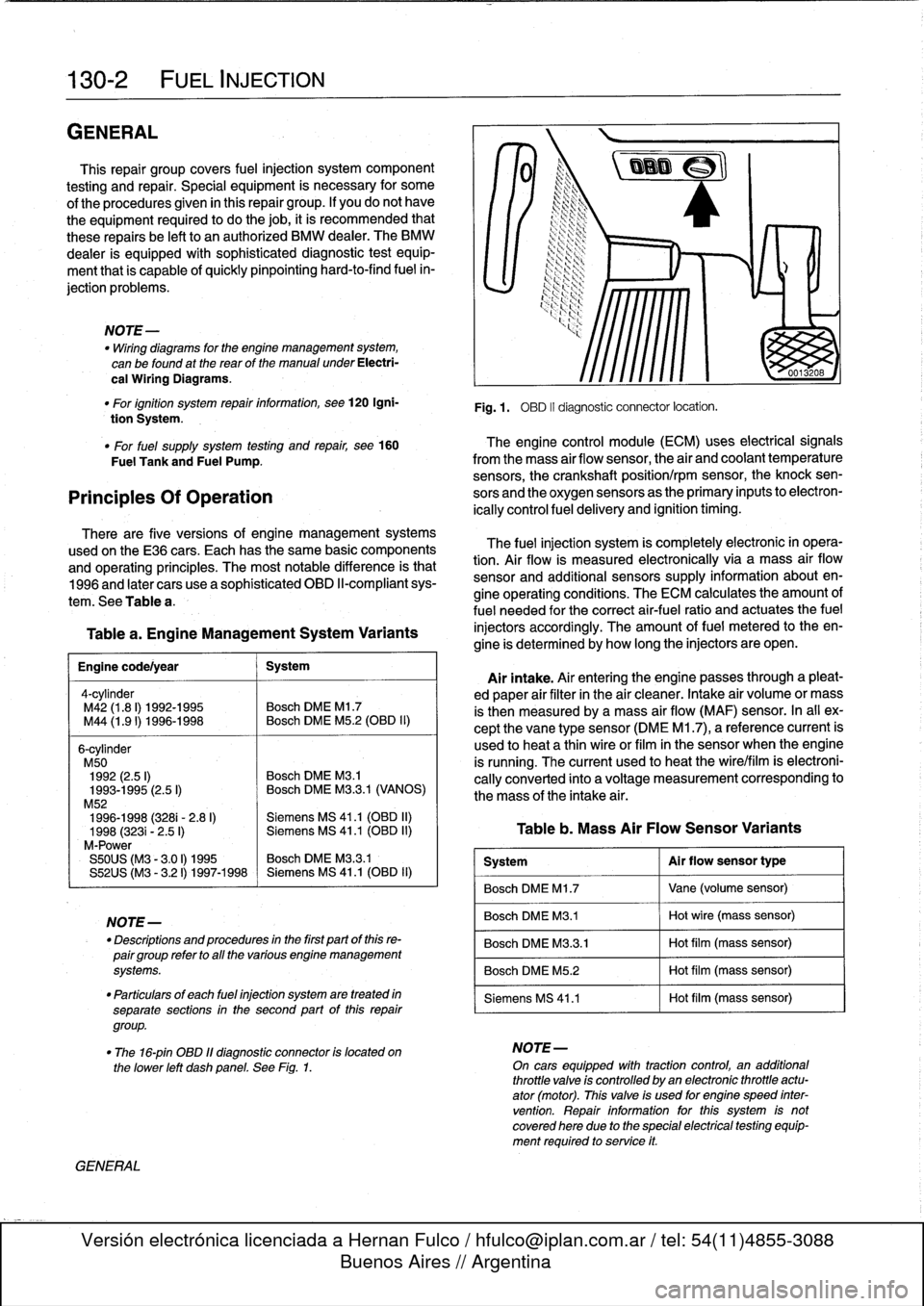
Fig
.1
.
OBD
II
diagnostic
connector
locatíon
.
The
fuel
injection
system
is
completely
electronic
in
opera-
tion
.
Air
flow
is
measured
electronically
via
a
mass
air
flow
sensor
and
additional
sensors
supply
information
about
en-
gine
operating
conditions
.
The
ECM
calculates
the
amount
of
fuel
needed
for
the
correct
air-fuel
ratio
and
actuates
the
fuel
injectors
accordingly
.
The
amount
offuel
metered
to
theen-
gine
is
determined
by
how
long
the
injectors
are
open
.
Airintake
.
Air
entering
the
engine
passes
through
a
pleat-
ed
paper
air
filter
in
the
air
cleaner
.
Intake
air
volume
or
mass
is
then
measured
bya
mass
air
flow
(MAF)
sensor
.
In
al¡
ex-
cept
the
vane
type
sensor
(DME
M1
.7),
a
reference
current
is
used
to
heat
a
thin
wireor
film
in
the
sensor
when
the
engine
is
running
.
The
current
used
to
heat
the
wire/film
is
electroni-
cally
converted
into
a
voltage
measurement
corresponding
to
the
mass
of
the
intake
air
.
Table
b
.
Mass
Air
Flow
Sensor
Variants
System
Al
r
flow
sensor
type
Bosch
DME
M1
.7
Vane
(volume
sensor)
Bosch
DME
M3
.1
Hot
wire
(mass
sensor)
Bosch
DME
M3
.3
.1
Hot
film
(mass
sensor)
Bosch
DME
M5
.2
Hot
film
(mass
sensor)
Siemens
MS
41
.1
Hot
film
(mass
sensor)
"
The
16-pin
OBD
11
diagnostic
connector
is
located
on
NOTE-
the
lower
left
dashpanel
.
See
Fig
.
1
.
On
cars
equipped
wíth
tractioncontrol,
an
additional
throttle
valve
is
controlled
by
an
electronic
throttle
actu-
ator
(motor)
.
This
valve
is
used
for
engine
speed
inter
vention
.
Repair
information
forthis
system
is
notcovered
here
due
to
the
special
electrical
testing
equip-
ment
required
to
service
it
.
Page 161 of 759
u0
I
.[
Ia
Fig
.
21
.
Air
flow
sensor
harness
connector
terminal
identification
.
4
.
Replacing
air
flow
sensor
:
"
Remove
large
band
clamp
attaching
air
boot
to
sensor
.
"
Remove
airfiltertop
cover,
then
remove
airflow
sensor
mounting
nuts
inside
cover
.
"
Reconnect
air
boot
and
harness
connector
.
Engine
coolant
temperature
(ECT)
sensor,
testing
and
replacing
The
engine
coolant
temperature
(ECT)
sensor
sends
con-
tinuous
engine
coolant
temperature
information
to
the
ECM
.
As
temperature
increases,
sensor
resistance
decreases
.
"
With
harness
connector
disconnected,
check
resis-
tance
across
sensor
terminals
.
"
Compare
tests
results
to
values
in
Table
d
.
FUEL
INJECTION
130-
1
5
0011984
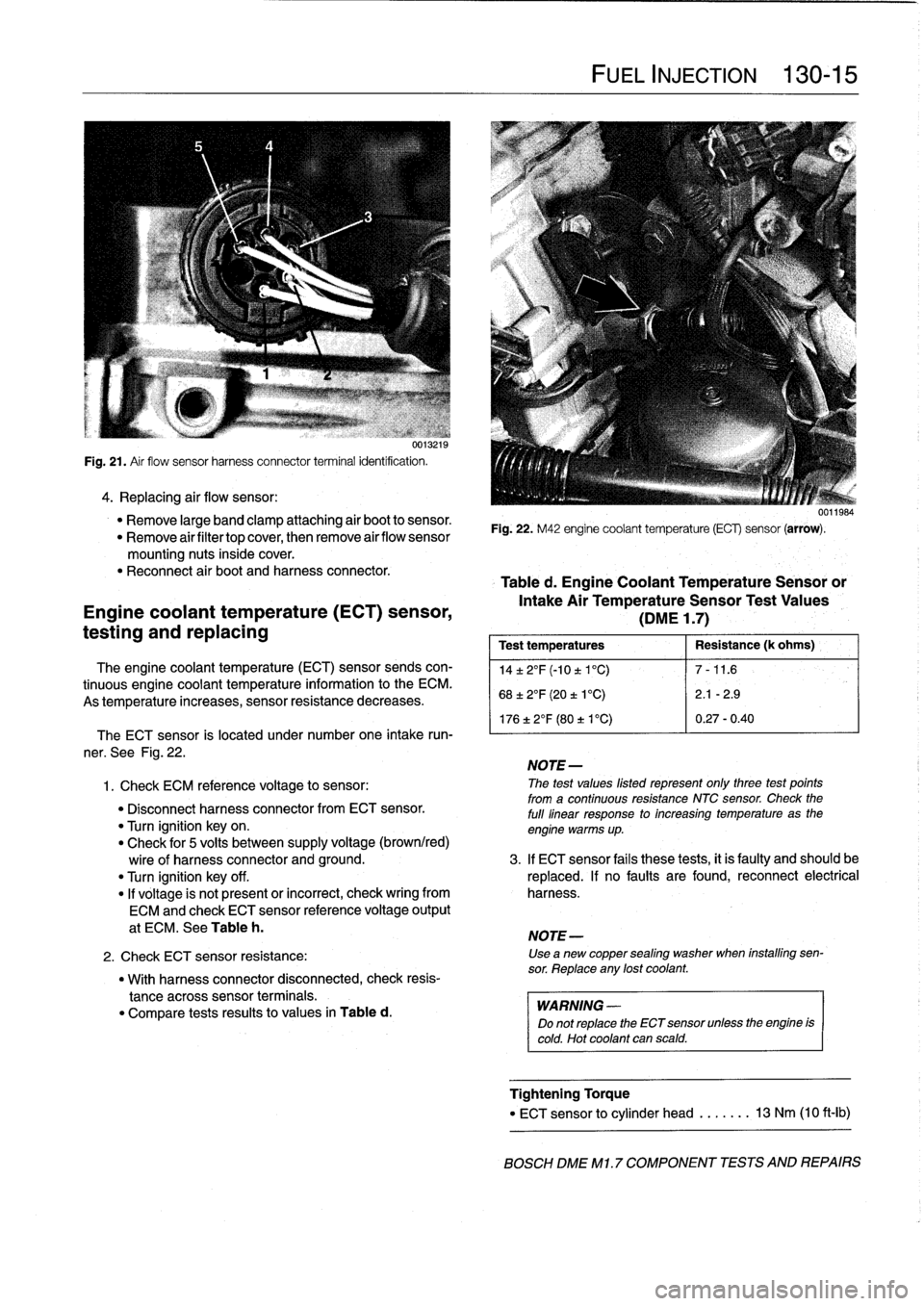
Fig
.
22
.
M42
engine
coolant
temperature
(ECG
sensor
(arrow)
.
Table
d
.
Engine
Coolant
Temperature
Sensoror
Intake
Air
TemperatureSensor
Test
Values
(DME
1
.7)
Test
temperatures
Resistance
(k
ohms)
',
14±2°F(-10t1°C)
7-11
.6
68±2°F
(20
t
1
°C)
2
.1
-2
.9
176
±
2°F
(80
t
V
C)
0
.27-0
.40
The
ECT
sensor
is
located
under
number
one
intake
run-
'
ner
.
See
Fig
.
22
.
NOTE-
1
.
Check
ECM
referente
voltage
to
sensor
:
The
test
values
listed
represent
only
three
test
points
from
a
continuous
resistance
NTC
sensor
.
Check
the
"
Disconnect
harness
connectorfrom
ECT
sensor
.
full
linear
response
to
increasing
temperature
as
the
"
Turn
ignition
key
on
.
engine
warms
up
.
"
Check
for
5
volts
between
supply
voltage
(brown/red)
wire
of
harness
connector
and
ground
.
3
.
If
ECT
sensor
fails
these
tests,
it
is
faulty
and
should
be
"
Turn
ignition
key
off
.
replaced
.
If
no
faults
are
found,
reconnect
electrical
"
If
voltage
is
not
present
or
incorrect,
check
wring
from
harness
.
ECM
and
check
ECT
sensor
reference
voltage
output
at
ECM
.
See
Table
h
.
NOTE-
2
.
Check
ECT
sensor
resistance
:
Use
a
new
copper
sealing
washer
when
installing
sen-
sor
.
Reptace
any
lost
coolant
.
WARNING
-
Do
not
replace
the
ECT
sensor
unlessthe
engine
is
cold
.
Hot
coolant
can
scald
.
Tightening
Torque
"
ECT
sensor
to
cylinder
head
.....
..
13
Nm
(10
ft-Ib)
BOSCH
DME
M1
.7
COMPONENT
TESTS
AND
REPAIRS
Page 164 of 759
130-18
FUEL
INJECTION
The
engine
coolant
temperature
(ECT)
sensor
sends
con-
tinuous
engine
coolant
temperature
information
to
the
ECM
.
Fig
.
26
.
Mass
air
flow
sensor
terminalidentifcation
on
carswith
DME
As
temperature
increases
sensor
resistance
decreases
.
M3
.1
fuel
injection
.
Mass
air
flow
sensor
(hot
film),
testing
and
replacing
MOTE-
A
burn-off
cycle
is
not
used
on
hot
film
sensors
.
8
.
With
ignition
off,
disconnect
harness
connector
from
air
ECT
Sensor
Location
flow
sensor
.
Using
a
digital
multimeter,
check
resis-
"
M50/S50US
engine
............
left
side
of
cylinder
tance
at
terminals
listed
.
head
under
intake
manifold
Air
Flow
Sensor
Test
Values
(DMEM3
.1)
"
Terminals
5
and
6
.
.
.
.........
..
.
..
....
3-4
ohms
If
any
faults
are
found,
check
wiring
lo
and
from
the
ECM
.
Make
ECM
pinout
test
as
listed
in
See
Table
i
.
Main
power
to
air
flow
sensor
comes
from
DME
main
relay
.
On
cars
with
DME
M3
.3
.1
a
hot
film
mass
air
flow
sensor
is
used
.
When
the
engine
is
running,
a
current
is
used
lo
heat
a
thinfilm
in
the
center
of
the
sensor
.
This
current
is
electroni-
cally
converted
into
a
voltage
measurement
corresponding
to
the
mass
of
intake
air
.
If
thehot
film
breaks
or
if
there
is
no
output
from
the
air
flow
sensor,
the
ECM
automatically
switches
to
a
"limp-home"
mode
and
tucos
on
the
Check
Engine
light
.
The
engine
can
usually
be
started
and
driven
.
The
air
flow
sensor
has
no
inter-
nal
moving
parts
and
cannot
be
senricedor
adjusted
.
CA
UTION-
Use
only
a
digital
multimeter
when
checking
the
mass
air
flow
sensor
.
An
analogmetercan
dam-
age
the
air
flow
sensor
.
BOSCH
DME
M3
.
1
AND
M32
.1
COMPONENT
TESTS
AND
REPAIRS
1
.
Disconnect
harnessconnector
from
air
flow
sensor
.
2
.
Turn
ignition
on
and
check
for
voltage
and
ground
at
connector
.
There
should
beground
at
pin
1
.
There
should
be
positive
(+)
battery
voltage
at
pin
3
.
If
any
faults
are
found,
check
wiring
to
and
from
ECM
.
Make
ECM
pinout
test
.
See
Table
j
.
NOTE-
Positive
(+)
battery
voltage
to
air
flow
sensor
comes
from
DME
main
relay
when
the
ignition
is
switch
on
orengine
running
.
Engine
coolant
temperature
(ECT)
sensor,
testing
and
replacing
0012704
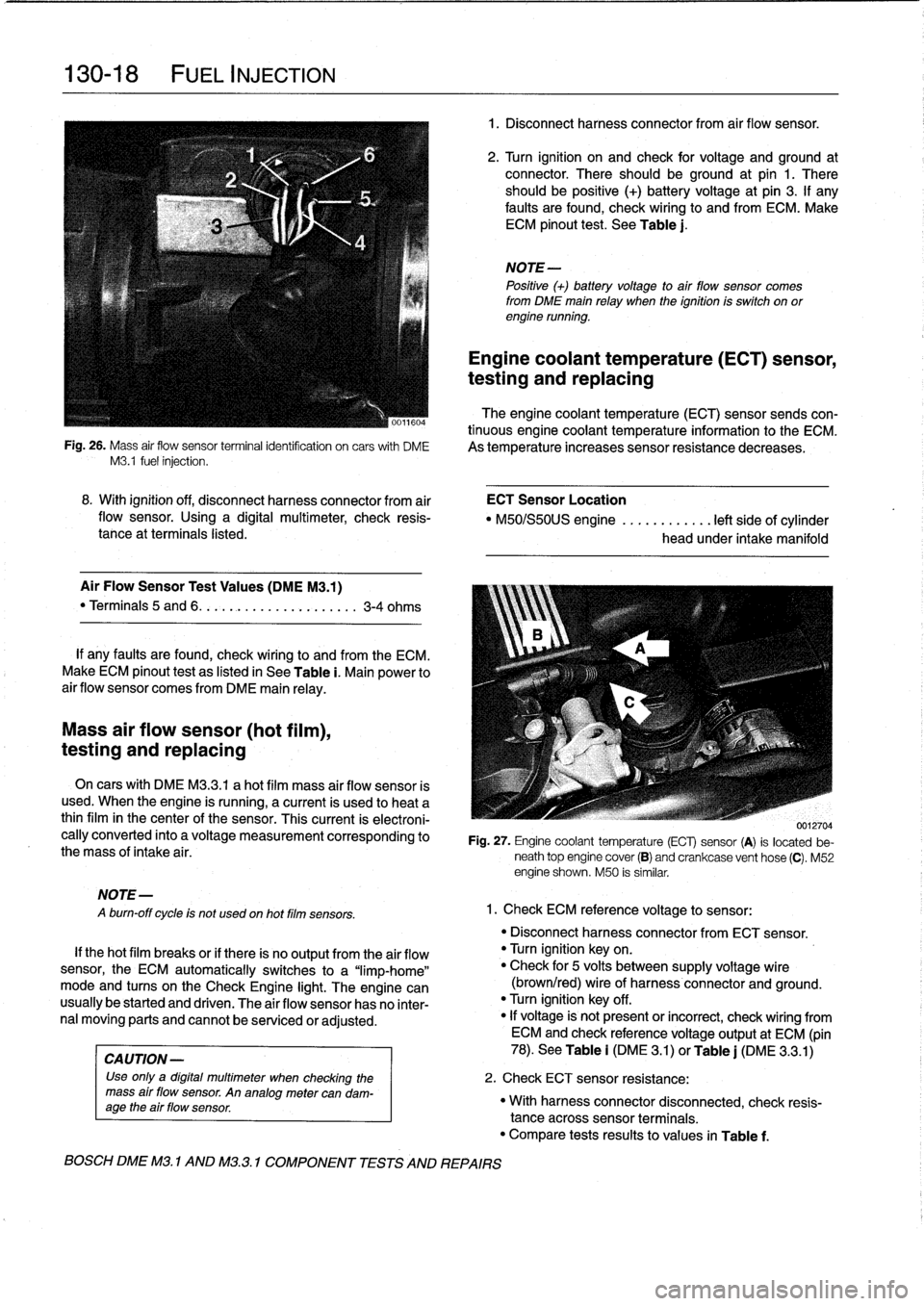
Fig
.
27
.
Engine
coolant
temperature
(ECT)
sensor
(A)
is
located
be-
neath
top
engine
cover
(B)
and
crankcase
vent
hose
(C)
.
M52
engine
shown
.
M50
is
similar
.
1
.
Check
ECM
reference
voltage
to
sensor
:
"
Disconnect
harnessconnector
from
ECT
sensor
.
"
Turn
ignition
keyon
.
"
Check
for
5
volts
between
supply
voltage
wire
(brown/red)
wire
of
harness
connector
and
ground
.
"
Turn
ignition
key
off
.
"
If
voltage
is'
not
present
or
incorrect,
check
wiring
from
ECM
and
check
referencevoltage
output
at
ECM
(pin
78)
.
See
Table
i
(DM
E
3
.1)
or
Table
j
(DME
3
.3
.1)
2
.
Check
ECT
sensor
resistance
:
"
With
harnessconnector
disconnected,
check
resis-
tance
acrosssensor
terminals
.
"
Compare
tests
results
to
values
in
Table
f
.