ECU BMW M4 2016 Owner's Guide
[x] Cancel search | Manufacturer: BMW, Model Year: 2016, Model line: M4, Model: BMW M4 2016Pages: 228, PDF Size: 4.88 MB
Page 153 of 228
Storage compartmentsVehicle equipmentThis chapter describes all standard, national
and special equipment provided in the model
series. Equipment not available in the vehicle is
therefore also described, for example the se‐
lected special equipment or national version.
This also applies to safety-relevant functions
and systems. Comply with the relevant na‐
tional regulations when using the correspond‐
ing functions and systems.
Notes WARNING
Loose objects in the interior can be
thrown into the interior during the journey, for
example in an accident or during braking and
evasive manoeuvres. Danger of injury. Secure
loose objects in the interior.◀
ATTENTION
Anti-slip mats can damage the dash‐
board. Danger of damage to property. Do not
use anti-slip mats.◀
Storage options The following storage options are located in
the interior:▷Glove box on the passenger side, see
page 153.▷Glove box on the driver's side, see
page 154.▷Without smoker's package: front compart‐
ment, in front of cupholders, see
page 154.▷Storage compartment in the front centre
armrest, see page 154.▷Pockets in the doors, see page 154.▷Nets on the backrests of the front seats.▷Storage compartment between the rear
seats, see page 155.
Glove box
Front passenger's side
Note WARNING
The glove box projects into the interior
when it is opened. Objects in the glove box can
be thrown into the interior during the journey,
for example in an accident or during braking
and evasive manoeuvres. Danger of injury. Im‐
mediately close the glove box after using it.◀
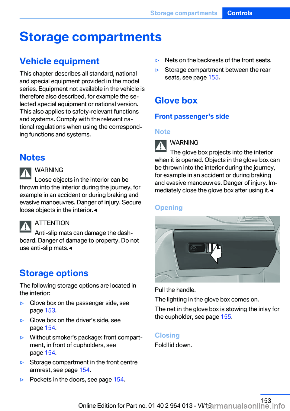
Opening
Pull the handle.
The lighting in the glove box comes on.
The net in the glove box is stowing the inlay for
the cupholder, see page 155.
Closing
Fold lid down.
Seite 153Storage compartmentsControls153
Online Edition for Part no. 01 40 2 964 013 - VI/15
Page 156 of 228
Storage compartments in the
boot
Storage compartment
There is a storage compartment on the left.
On the right-hand side there is a storage com‐
partment for on-board toolkit, see page 193,
and first-aid kit, see page 203.
Net
Smaller objects can be stowed in the net on
the left-hand side.
Bag holders WARNING
Incorrect use of the holders can repre‐
sent a danger, for example if objects fly around
in the case of braking and evasive manoeuvres.
Danger of injury and damage to property. Only
hang light objects, for example shopping bags,
on the holders. Only transport heavy luggage
with suitable means of securing in the boot.◀
In the boot there is a bag holder on every side.
Tensioning strap
There is a tensioning strap on the right-hand
trim panel for securing small objects.
Lashing eyes in the boot
For securing the load, see page 166, four lash‐
ing eyes are in the boot.
Floor net
For securing the load, see page 166, and for
keeping small parts, the floor net can also be
used.
Storage compartment under the boot
floor
For the storage compartment under the boot
floor, do not exceed a maximum permitted load
of 20 kg, approx. 44 lb.
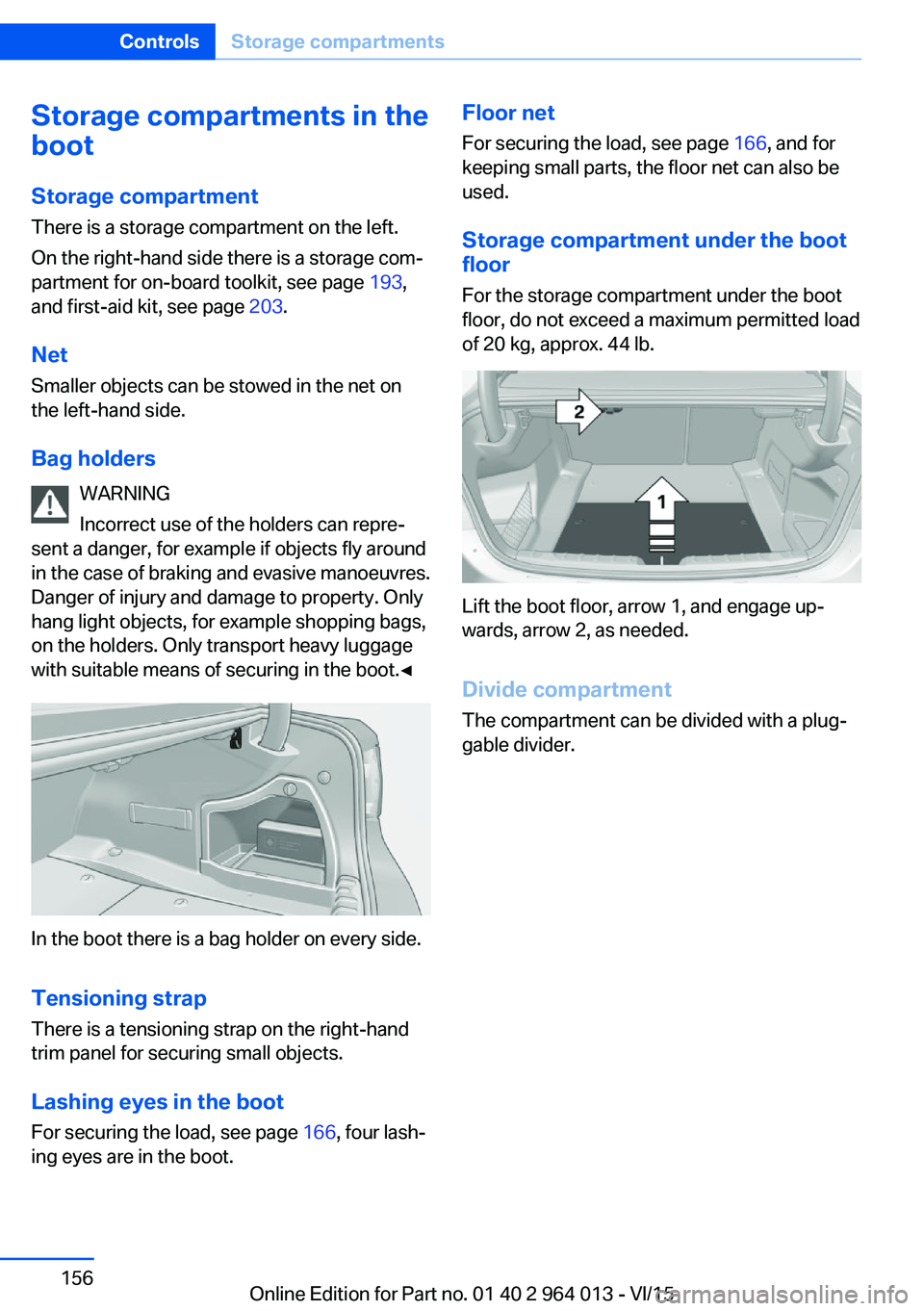
Lift the boot floor, arrow 1, and engage up‐
wards, arrow 2, as needed.
Divide compartment
The compartment can be divided with a plug‐
gable divider.
Seite 156ControlsStorage compartments156
Online Edition for Part no. 01 40 2 964 013 - VI/15
Page 164 of 228
Applying the brakes fully is the most effective
way of braking in situations in which this is
necessary.
The vehicle can be steered. Any obstacles can
be avoided with steering wheel movements
that are as calm as possible.
A pulsing of the brake pedal shows that ABS is
regulating.
In certain braking situations, the perforated
brake disks can cause functional noise. How‐
ever, this has no effect on the efficiency and
operational safety of the brakes.
Objects in the range of movement of
the pedals and in the footwell
WARNING
Objects in the driver's footwell can re‐
strict the pedal travel, or block a pedal that has
been pressed. Danger of accidents. Stow
items in the vehicle so that they are secure and
cannot get into the driver's footwell. Only use
floor mats that have been categorised as ap‐
propriate for the vehicle and that can be fas‐
tened accordingly. Do not use any loose floor
mats, and do not place several floor mats on
top of one another. Make sure that there is suf‐
ficient space for the pedals. Ensure that the
floor mats are securely reattached after having
been removed, for example for cleaning.◀
Wet roads
In damp weather, if road grit has been spread
or there is heavy rain, apply the brakes lightly
every few kilometres/miles.
In doing so, do not obstruct other road users.
The resulting heat dries the brake discs and
pads.
The braking force will be available immediately
if needed.Downhill gradients
WARNING
Even slight, continuous pressure on the
brake pedal can cause overheating, brake pad
wear or even brake system failure. Danger of
accidents. Avoid excessive loads on the
brake.◀
WARNING
When idling or with the engine switched
off, safety-relevant functions are restricted or
no longer available, for example the braking ef‐
fect of the engine or power assistance for the
braking force and steering. Danger of acci‐
dents. Do not drive at idle speed or with the
engine switched off.◀
When driving on long or steep downhill
stretches, use the gear in which the least brak‐
ing is required. Otherwise the brake system
can overheat and braking action is reduced.
Manual gearbox:
The braking effect can be additionally in‐
creased by shifting down, even into first gear, if
applicable.
M double clutch transmission:
The braking action of the engine can be boos‐
ted further by shifting down in sequential
mode, see page 75.
Corrosion of the brake disc Corrosion of the brake discs and contamina‐
tion of the brake pads increase with the
following circumstances:▷Low mileage.▷Extended periods when the vehicle is not
used.▷Infrequent use of the brakes.
Corrosion occurs when the minimum pressure
that must be exerted by the pads during brake
applications to clean the discs is not reached.
Seite 164Driving hintsDriving precautions164
Online Edition for Part no. 01 40 2 964 013 - VI/15
Page 166 of 228
LoadsVehicle equipment
This chapter describes all standard, national
and special equipment provided in the model
series. Equipment not available in the vehicle is
therefore also described, for example the se‐
lected special equipment or national version.
This also applies to safety-relevant functions
and systems. Comply with the relevant na‐
tional regulations when using the correspond‐
ing functions and systems.
Notes WARNING
A high gross vehicle weight can cause
the tyres to overheat, causing internal damage
and a sudden loss of tyre pressure. Danger of
accidents. Comply with the permitted load in‐
dex of the tyre, and do not exceed the permit‐
ted gross vehicle weight.◀
WARNING
If the permitted total weight and the per‐
mitted axle loads are exceeded, operational
safety of the vehicle is not ensured anymore.
Danger of accidents. Do not exceed the per‐
mitted total weight and permitted axle loads.◀
ATTENTION
Liquids in the boot can cause damage.
Danger of damage to property. Make sure that
no liquids leak out in the boot.◀
WARNING
Loose objects in the interior can be
thrown into the interior during the journey, for
example in an accident or during braking and
evasive manoeuvres. Danger of injury. Secure
loose objects in the interior.◀Stowing transported loads▷Wrap protective material around sharp cor‐
ners and edges of the load.▷Heavy transported load: stow as far for‐
ward and as low down as possible, ideally
directly behind the rear backrests.▷Very heavy transported load: with no pas‐
sengers on the back seat, insert both outer
seat belts into the respective opposite
buckles.▷Fully fold down the rear-seat backrest if
the load is to be stowed accordingly.▷Do not stack storage goods above the up‐
per edge of the backrests.
Securing transported loads
Lashing eyes in the boot
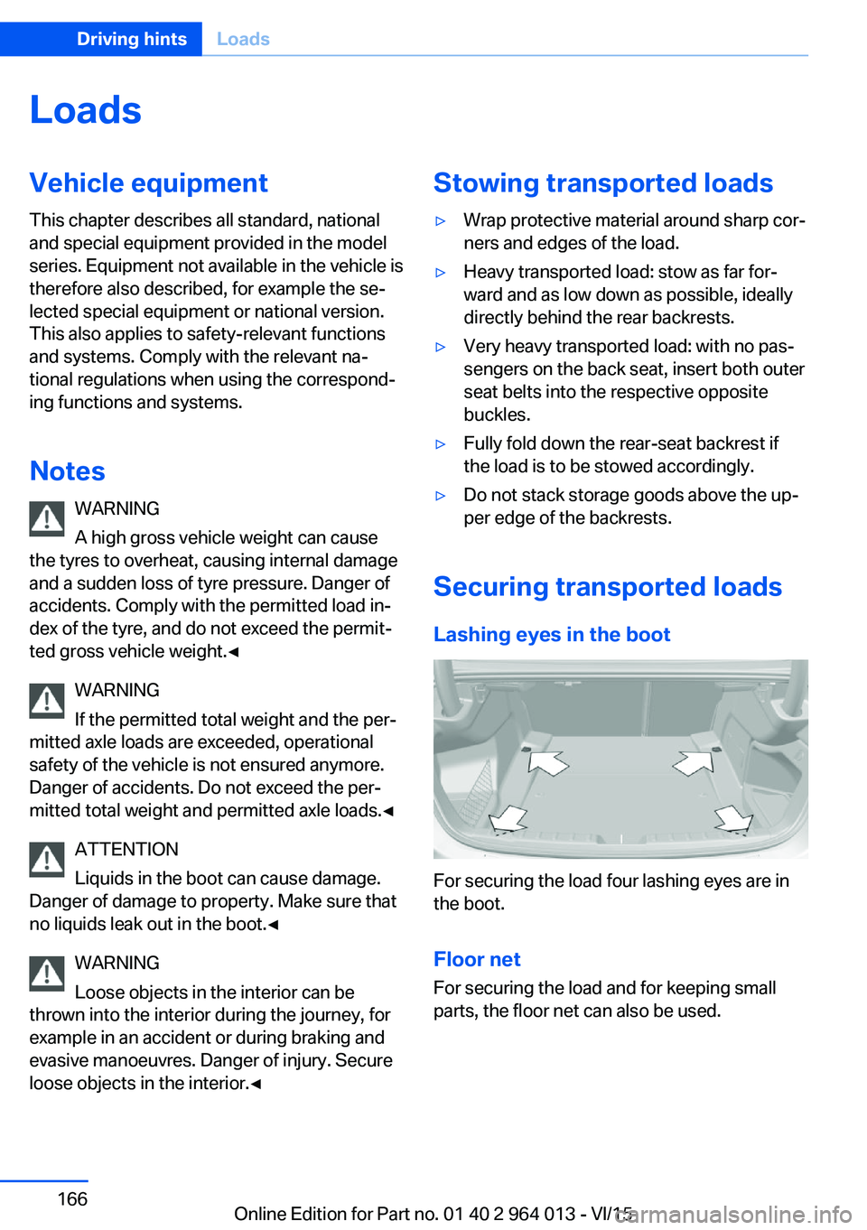
For securing the load four lashing eyes are in
the boot.
Floor net
For securing the load and for keeping small
parts, the floor net can also be used.
Seite 166Driving hintsLoads166
Online Edition for Part no. 01 40 2 964 013 - VI/15
Page 167 of 228
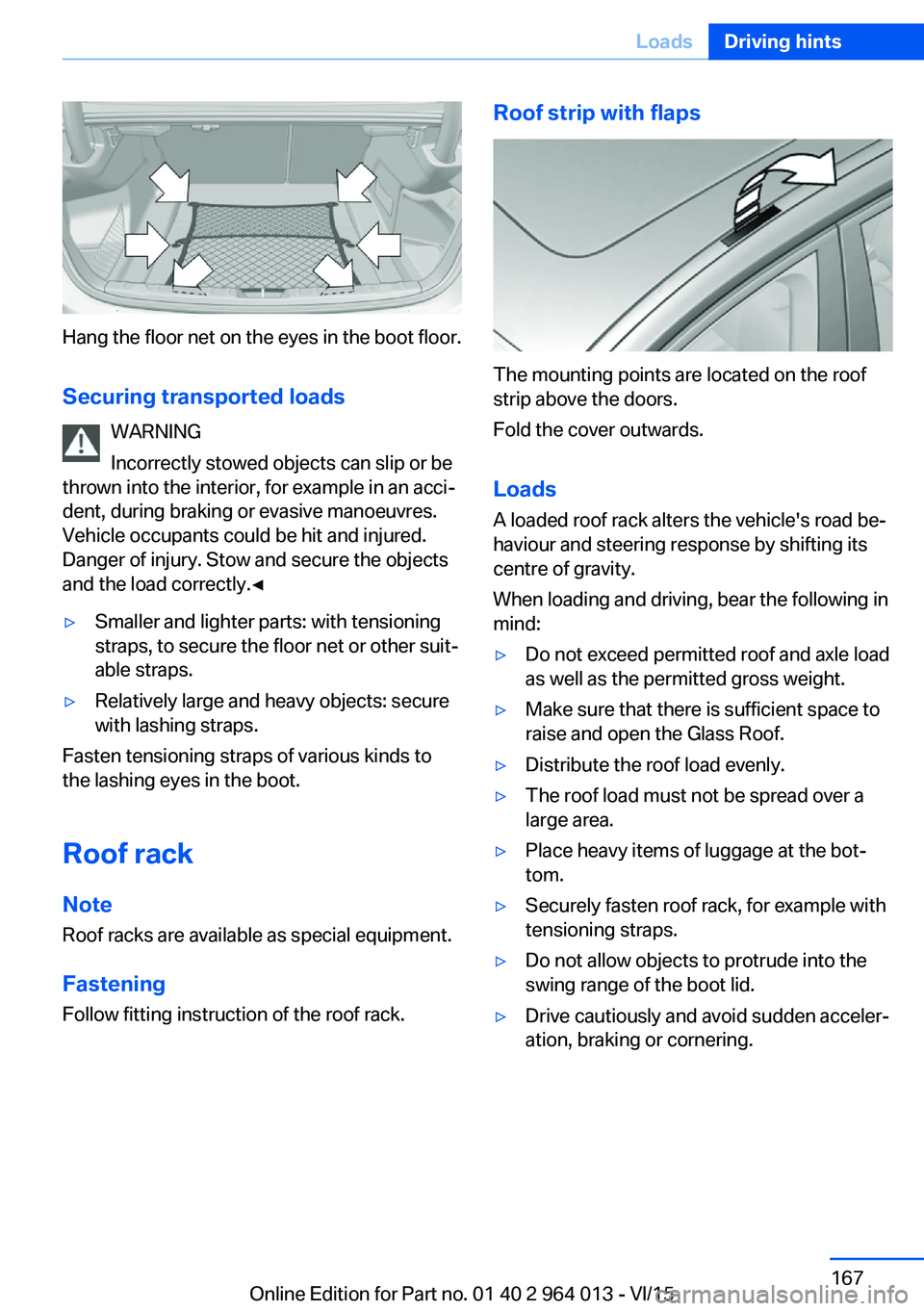
Hang the floor net on the eyes in the boot floor.Securing transported loads WARNING
Incorrectly stowed objects can slip or be
thrown into the interior, for example in an acci‐
dent, during braking or evasive manoeuvres.
Vehicle occupants could be hit and injured.
Danger of injury. Stow and secure the objects
and the load correctly.◀
▷Smaller and lighter parts: with tensioning
straps, to secure the floor net or other suit‐
able straps.▷Relatively large and heavy objects: secure
with lashing straps.
Fasten tensioning straps of various kinds to
the lashing eyes in the boot.
Roof rack Note
Roof racks are available as special equipment.
Fastening Follow fitting instruction of the roof rack.
Roof strip with flaps
The mounting points are located on the roof
strip above the doors.
Fold the cover outwards.
Loads
A loaded roof rack alters the vehicle's road be‐
haviour and steering response by shifting its
centre of gravity.
When loading and driving, bear the following in
mind:
▷Do not exceed permitted roof and axle load
as well as the permitted gross weight.▷Make sure that there is sufficient space to
raise and open the Glass Roof.▷Distribute the roof load evenly.▷The roof load must not be spread over a
large area.▷Place heavy items of luggage at the bot‐
tom.▷Securely fasten roof rack, for example with
tensioning straps.▷Do not allow objects to protrude into the
swing range of the boot lid.▷Drive cautiously and avoid sudden acceler‐
ation, braking or cornering.Seite 167LoadsDriving hints167
Online Edition for Part no. 01 40 2 964 013 - VI/15
Page 186 of 228
Different messages are shown on the display,
depending on the engine oil level. Follow these
messages.
If there is too little engine oil, within the next
200 km, approximately 120 miles top up en‐
gine oil, see page 186.
Detailed measurement
Principle In the detailed measurement, the engine oil
level is checked and shown on a scale.
If the engine oil level reaches the minimum, a
Check Control message is shown.
During the measurement, the idle speed is
slightly raised.
Requirements▷Vehicle is on an even road.▷Manual gearbox: gear lever in neutral posi‐
tion, clutch and accelerator pedal not de‐
pressed.▷M double clutch transmission: selector
lever in selector lever position N and accel‐
erator pedal not depressed.▷Engine is running and is at operating tem‐
perature.
Carrying out a detailed measurement
Carry out a detailed measurement of the en‐
gine oil level:
1."Vehicle information"2."Vehicle status"3. "Measure engine oil level"4."Start measurement"
The engine oil level is checked and shown on a
scale.
Duration: approximately 1 minute.
Adding engine oil
Notes ATTENTION
Too little engine oil causes engine dam‐
age. Danger of damage to property.
Top up the engine oil within the next 200 km,
approximately 120 miles.◀
ATTENTION
Too much engine oil can damage the en‐
gine or the catalytic converter. Danger of dam‐
age to property. Do not top up with too much
engine oil. If you fill too much engine oil, have
the excess extracted by a Service Partner or a
qualified specialist workshop.◀
WARNING
Service products, for example oils,
greases, coolants and fuels, can contain sub‐
stances that are harmful to health. Danger of
injury or life. Comply with the notes on the
containers. Do not allow service products to
come into contact with clothing, skin eyes. Do
not pour service products into other bottles.
Keep service products out of the reach of chil‐
dren.◀
General Do not top up engine oil unless message isdisplayed in instrument cluster. The top-up
amount is specified in the message on the in‐
strument cluster.
Switch off the ignition and securely stop the
vehicle before topping up with engine oil.
Spilled engine oil can damage carbon parts.
Wipe up spilled engine oil with a lint-free cloth.
Overview
The oil filler neck is in the engine compart‐
ment, see page 182.Seite 186MobilityEngine oil186
Online Edition for Part no. 01 40 2 964 013 - VI/15
Page 193 of 228
Replacing partsVehicle equipmentThis chapter describes all standard, national
and special equipment provided in the model
series. Equipment not available in the vehicle is
therefore also described, for example the se‐
lected special equipment or national version.
This also applies to safety-relevant functions
and systems. Comply with the relevant na‐
tional regulations when using the correspond‐
ing functions and systems.
On-board tool kit
The on-board toolkit is located in a compart‐
ment on the right in the boot. Open the cover.
Replacing the wiper blades Note ATTENTION
The windscreen can be damaged if the
wiper arm drops onto the windscreen without
wiper blades fitted. Danger of damage to prop‐
erty. Hold the wiper arm firmly when changing
the wiper blades and do not put the wipers into
contact with the windscreen unless wiper
blades are fitted.◀
Wiper blades, replacing1.To replace the wiper blades, place the wip‐
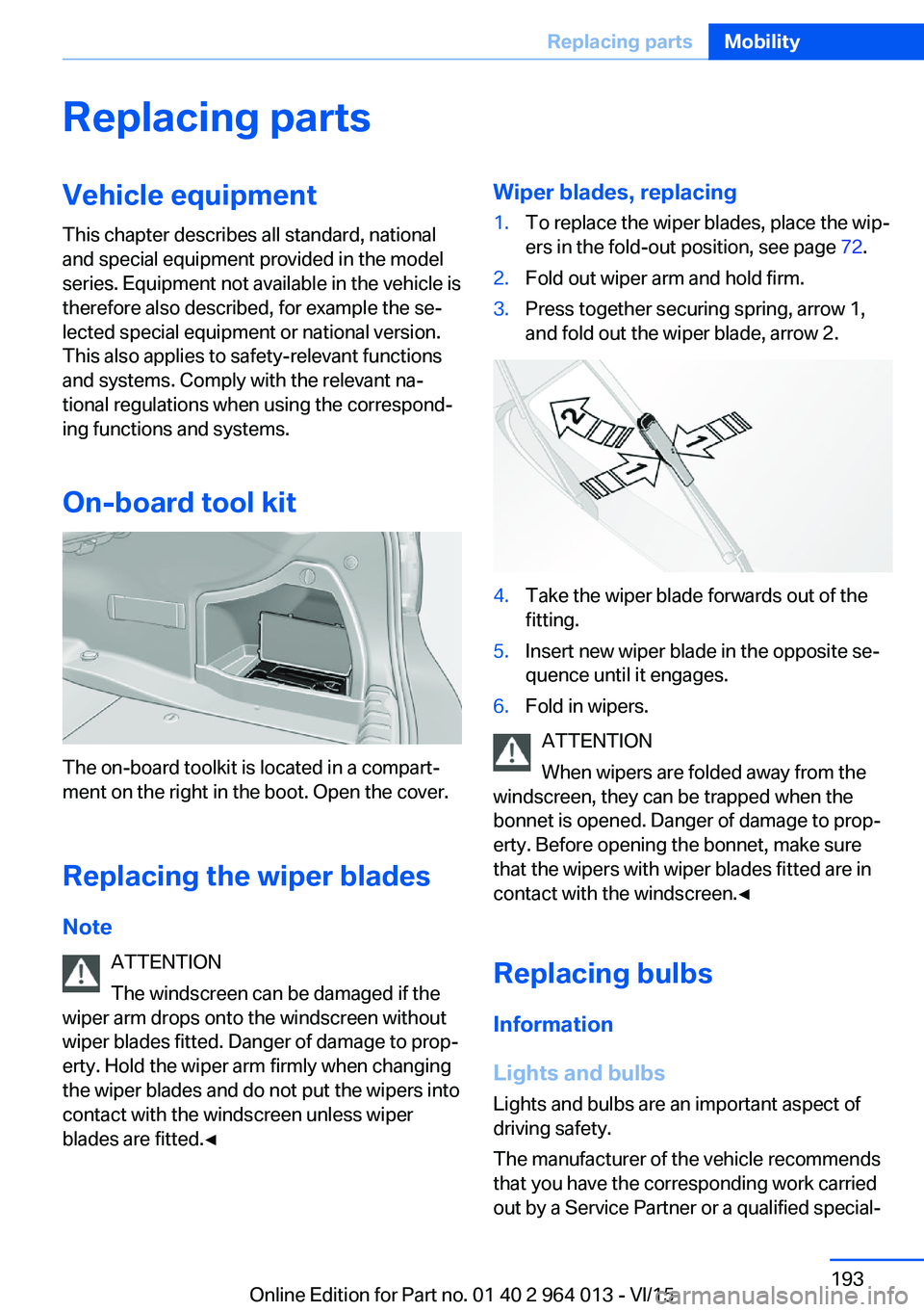
ers in the fold-out position, see page 72.2.Fold out wiper arm and hold firm.3.Press together securing spring, arrow 1,
and fold out the wiper blade, arrow 2.4.Take the wiper blade forwards out of the
fitting.5.Insert new wiper blade in the opposite se‐
quence until it engages.6.Fold in wipers.
ATTENTION
When wipers are folded away from the
windscreen, they can be trapped when the
bonnet is opened. Danger of damage to prop‐
erty. Before opening the bonnet, make sure
that the wipers with wiper blades fitted are in
contact with the windscreen.◀
Replacing bulbs
Information
Lights and bulbs
Lights and bulbs are an important aspect of
driving safety.
The manufacturer of the vehicle recommends
that you have the corresponding work carried
out by a Service Partner or a qualified special‐
Seite 193Replacing partsMobility193
Online Edition for Part no. 01 40 2 964 013 - VI/15
Page 195 of 228
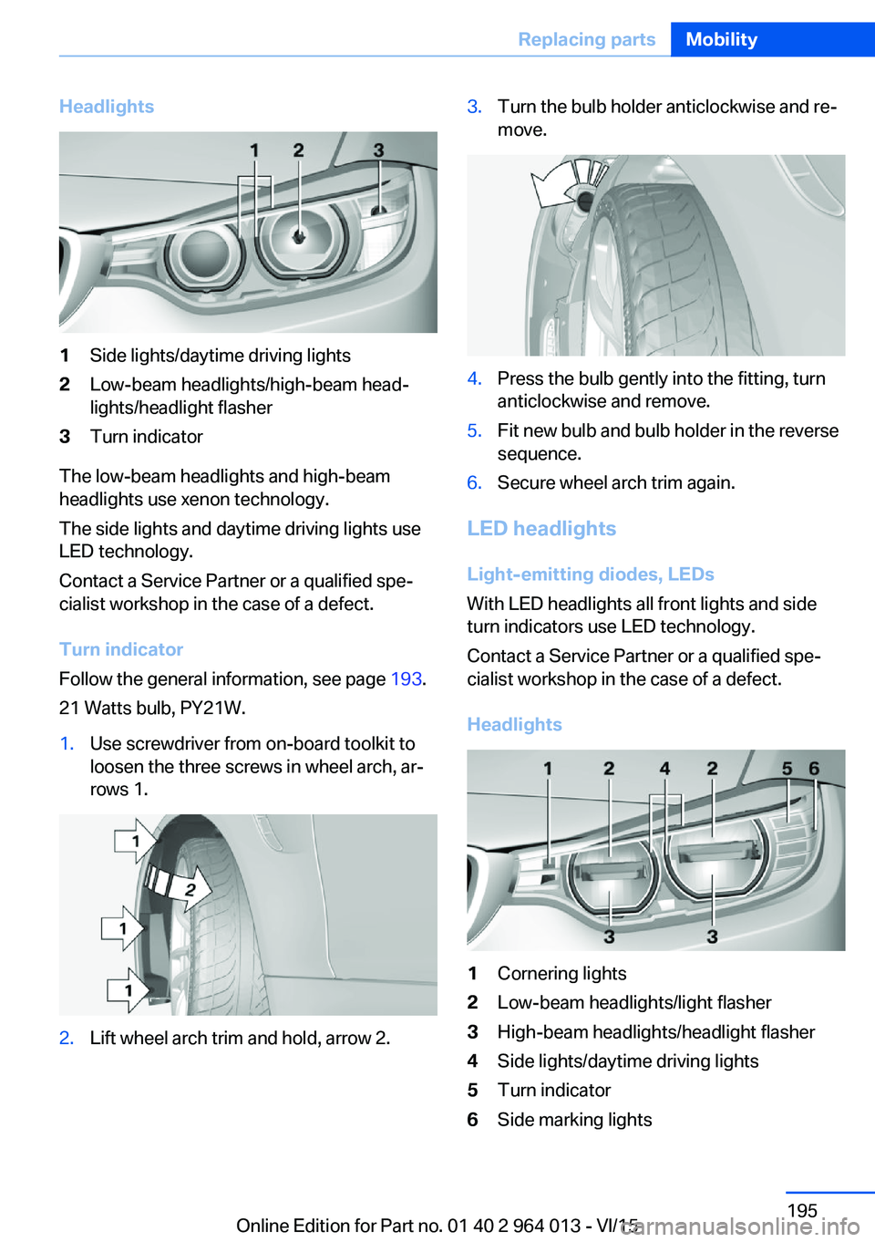
Headlights1Side lights/daytime driving lights2Low-beam headlights/high-beam head‐
lights/headlight flasher3Turn indicator
The low-beam headlights and high-beam
headlights use xenon technology.
The side lights and daytime driving lights use
LED technology.
Contact a Service Partner or a qualified spe‐
cialist workshop in the case of a defect.
Turn indicator
Follow the general information, see page 193.
21 Watts bulb, PY21W.
1.Use screwdriver from on-board toolkit to
loosen the three screws in wheel arch, ar‐
rows 1.2.Lift wheel arch trim and hold, arrow 2.3.Turn the bulb holder anticlockwise and re‐
move.4.Press the bulb gently into the fitting, turn
anticlockwise and remove.5.Fit new bulb and bulb holder in the reverse
sequence.6.Secure wheel arch trim again.
LED headlights
Light-emitting diodes, LEDs
With LED headlights all front lights and side
turn indicators use LED technology.
Contact a Service Partner or a qualified spe‐
cialist workshop in the case of a defect.
Headlights
1Cornering lights2Low-beam headlights/light flasher3High-beam headlights/headlight flasher4Side lights/daytime driving lights5Turn indicator6Side marking lightsSeite 195Replacing partsMobility195
Online Edition for Part no. 01 40 2 964 013 - VI/15
Page 197 of 228
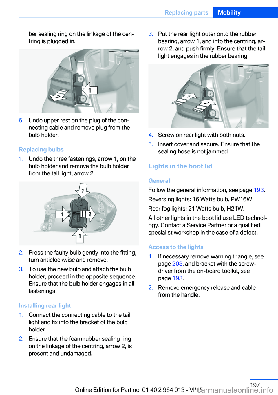
ber sealing ring on the linkage of the cen‐
tring is plugged in.6.Undo upper rest on the plug of the con‐
necting cable and remove plug from the
bulb holder.
Replacing bulbs
1.Undo the three fastenings, arrow 1, on the
bulb holder and remove the bulb holder
from the tail light, arrow 2.2.Press the faulty bulb gently into the fitting,
turn anticlockwise and remove.3.To use the new bulb and attach the bulb
holder, proceed in the opposite sequence.
Ensure that the bulb holder engages in all
fastenings.
Installing rear light
1.Connect the connecting cable to the tail
light and fix into the bracket of the bulb
holder.2.Ensure that the foam rubber sealing ring
on the linkage of the centring, arrow 2, is
present and undamaged.3.Put the rear light outer onto the rubber
bearing, arrow 1, and into the centring, ar‐
row 2, and push firmly. Ensure that the tail
light engages in the rubber bearing.4.Screw on rear light with both nuts.5.Insert cover and secure. Ensure that the
sealing hose is not jammed.
Lights in the boot lid
General
Follow the general information, see page 193.
Reversing lights: 16 Watts bulb, PW16W
Rear fog lights: 21 Watts bulb, H21W.
All other lights in the boot lid use LED technol‐
ogy. Contact a Service Partner or a qualified
specialist workshop in the case of a defect.
Access to the lights
1.If necessary remove warning triangle, see
page 203, and bracket with the screw‐
driver from the on-board toolkit, see
page 193.2.Remove emergency release and cable
from the handle.Seite 197Replacing partsMobility197
Online Edition for Part no. 01 40 2 964 013 - VI/15
Page 211 of 228
ATTENTION
Cleaning agents containing alcohol or
solvents, such as nitro thinners, cold cleans‐
ers, fuel or similar can damage plastic parts.
Danger of damage to property. Use a microfi‐
bre cloth to clean. Slightly moisten the cloth
with water.◀
Seat belts Dirt on the seat belts can interfere with the ac‐
tion of the reel and represent a safety hazard.
WARNING
Chemical cleaners can cause irreparable
damage to the fabric of the seat belts. Lack of protective effect of the seat belts. Danger ofinjury or life. Only use a mild soap and water
solution for cleaning the seat belts.◀
Clean only with a mild soap solution while still
fitted to the vehicle.
Never allow seat belts to retract unless they
are dry.
Carpets and foot mats WARNING
Objects in the driver's footwell can re‐
strict the pedal travel, or block a pedal that has
been pressed. Danger of accidents. Stow
items in the vehicle so that they are secure and
cannot get into the driver's footwell. Only use
floor mats that have been categorised as ap‐
propriate for the vehicle and that can be fas‐
tened accordingly. Do not use any loose floor
mats, and do not place several floor mats on
top of one another. Make sure that there is suf‐
ficient space for the pedals. Ensure that the
floor mats are securely reattached after having
been removed, for example for cleaning.◀
Floor mats can be removed from the vehicle to
enable the interior to be cleaned more thor‐
oughly.
In the event of heavy soiling, clean floor car‐
pets using a microfibre cloth and water or tex‐tile cleaner. In doing so, rub back and forth in
the direction of travel, otherwise the carpet can
become tangled.
Sensors/lenses of the camera
Clean sensors or lenses of the camera using a
cloth moistened with a small amount of a glass
detergent.
Displays/screens/protective sleeve of
the Head-Up Displays
ATTENTION
Chemical cleaners, moisture or fluids of
all kinds can damage the surface of displays
and screens. Danger of damage to property.
Use a clean, anti-static microfibre cloth to
clean.◀
ATTENTION
The surfaces of displays can be dam‐
aged due to improper cleaning. Danger of
damage to property. Avoid applying excessive
pressure and do not use abrasive materials.◀
Use a clean, anti-static microfibre cloth to
clean.
Clean the protective sleeve of the Head-Up
Display with a microfibre cloth and commer‐
cially available dishwashing liquid.
Laying up out of use
When the vehicle is laid up for longer than
three months, special measures are to be
taken. Further information is available from a
Service Partner or a qualified specialist work‐
shop.Seite 211General careMobility211
Online Edition for Part no. 01 40 2 964 013 - VI/15