tow BMW M4 2016 Owners Manual
[x] Cancel search | Manufacturer: BMW, Model Year: 2016, Model line: M4, Model: BMW M4 2016Pages: 228, PDF Size: 4.88 MB
Page 20 of 228
▷The system recognises capital and small
letters. To enter small and capital letters
and numbers, it may be necessary to the
change input mode, for example, when
identically writing small and capital letters.
Change between upper/lower case, num‐
bers and symbols, see page 23.▷Enter symbols as they are displayed on the
Control Display.▷Relevant symbols, such as accents or full
stops are always known ambiguously with
the letter. The input option depends on the
language that has been set. You may need
to enter special characters using the Con‐
troller.▷To delete a character, swipe the touchpad
towards the left.▷To enter a space, swipe towards the right
in the middle of the touchpad.▷To enter a hyphen, swipe towards the right
in the upper area of the touchpad.▷To enter an underscore, swipe towards the
right in the lower area of the touchpad.
Operating interactive map and
Internet
The Interactive map of the navigation system
and websites can be moved using the touch‐
pad.
FunctionControlsMove interactive map or
web pages.Swipe in the ap‐
propriate direction.Enlarge/reduce interac‐
tive map or web pages.Pinch or open up
your fingers on the
touchpad.Show menu or open a
link on the Internet.Tap once.
Adjusting the settings
Settings on the Control Display, such as vol‐
ume, for example, can be made using the
touchpad. To do this swipe left or right as ap‐
propriate.
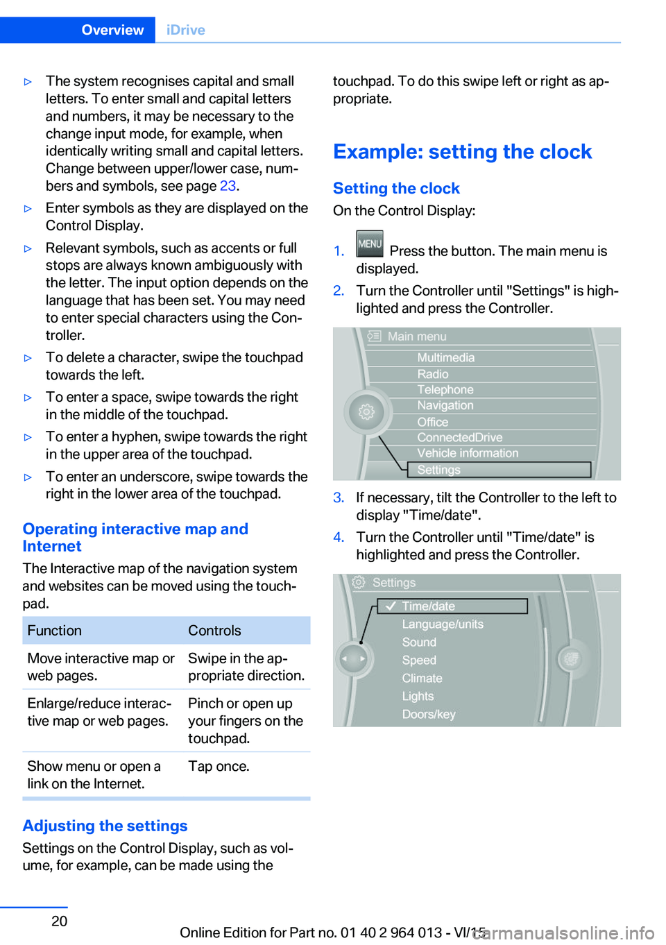
Example: setting the clock Setting the clock
On the Control Display:1. Press the button. The main menu is
displayed.2.Turn the Controller until "Settings" is high‐
lighted and press the Controller.3.If necessary, tilt the Controller to the left to
display "Time/date".4.Turn the Controller until "Time/date" is
highlighted and press the Controller.Seite 20OverviewiDrive20
Online Edition for Part no. 01 40 2 964 013 - VI/15
Page 42 of 228
Boot lid is opened and doors are un‐
locked.
Acknowledgement signal of the
vehicle
Settings are saved in active profile, see
page 33.
1."Settings"2."Doors/key"3."Turn signals for lock/unl."
Automatic locking
Settings are saved in active profile, seepage 33.
1."Settings"2."Doors/key"3.Select the desired function:▷"Automatic relock"
The vehicle is locked automatically af‐
ter a short while if no door is opened.▷"Lock after driving away"
On driving off, the vehicle is locked au‐
tomatically.
Calling up seat, mirror setting
The last adjusted driver's seat and exterior mir‐
ror position is saved for the currently used re‐
mote control.
When the vehicle is unlocked, this position is
called up automatically if the function has been
enabled.
WARNING
Danger of trapping when moving the
seats. Danger of injury or damage to property.
Before making the setting, make sure that the
movement area of the seat is clear.◀
Adjustment procedure is interrupted:
▷By operating the switch or the seat adjust‐
ment.▷By touching a button of the seat and mirror
memory.
Enabling setting
1."Settings"2."Doors/key"3."Last seat position autom."
Alarm system
PrincipleThe alarm system is triggered when the vehi‐cle is locked if:
▷A door, the bonnet or the the boot lid is
opened.▷Movements in the interior.▷The vehicle's incline changes, for instance
if an attempt is made to jack it up and steal
the wheels or to raise it prior to towing
away.▷There is an interruption in the power sup‐
ply from the battery.
The alarm system will respond briefly to unau‐
thorised attempts to access the vehicle as fol‐
lows:
▷Acoustic alarm.▷Switching on the hazard warning lights.
Arming and disarming
At the same time as unlocking and locking the
vehicle by remote control or Comfort Access
the alarm system is also disarmed or armed.
Door lock with alarm system armed Alarm system is deactivated if the vehicle is
unlocked using the door lock.
Boot lid with alarm system armed The boot lid can be opened even with the
alarm system armed.
Seite 42ControlsOpening and closing42
Online Edition for Part no. 01 40 2 964 013 - VI/15
Page 43 of 228
On closing the boot lid, it is locked again and
monitored, as long as the doors are locked.
The hazard warning system flashes once.
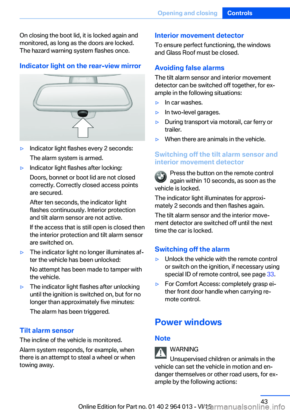
Indicator light on the rear-view mirror▷Indicator light flashes every 2 seconds:
The alarm system is armed.▷Indicator light flashes after locking:
Doors, bonnet or boot lid are not closed
correctly. Correctly closed access points
are secured.
After ten seconds, the indicator light
flashes continuously. Interior protection
and tilt alarm sensor are not active.
If the access that is still open is closed then
the interior protection and tilt alarm sensor
are switched on.▷The indicator light no longer illuminates af‐
ter the vehicle has been unlocked:
No attempt has been made to tamper with
the vehicle.▷The indicator light flashes after unlocking
until the ignition is switched on, but for no
longer than approximately five minutes:
The alarm has been triggered.
Tilt alarm sensor The incline of the vehicle is monitored.
Alarm system responds, for example, when
there is an attempt to steal a wheel or when
towing away.
Interior movement detector
To ensure perfect functioning, the windows
and Glass Roof must be closed.
Avoiding false alarms
The tilt alarm sensor and interior movement detector can be switched off together, for ex‐
ample in the following situations:▷In car washes.▷In two-level garages.▷During transport via motorail, car ferry or
trailer.▷When there are animals in the vehicle.
Switching off the tilt alarm sensor and
interior movement detector
Press the button on the remote control
again within 10 seconds, as soon as the
vehicle is locked.
The indicator light illuminates for approxi‐
mately 2 seconds and then flashes again.
The tilt alarm sensor and the interior move‐
ment detector are switched off until the next
time the car is locked.
Switching off the alarm
▷Unlock the vehicle with the remote control
or switch on the ignition, if necessary using
special ID of remote control, see page 33.▷For Comfort Access: completely grasp ei‐
ther front door handle when carrying re‐
mote control.
Power windows
Note WARNING
Unsupervised children or animals in the
vehicle can set the vehicle in motion and en‐
danger themselves or other road users, for ex‐
ample by the following actions:
Seite 43Opening and closingControls43
Online Edition for Part no. 01 40 2 964 013 - VI/15
Page 74 of 228
Reverse gear
Engage this position only when the vehicle is
stationary.
To overcome the resistance of the selector
lever move in a dynamic movement towards
the left and engage the reverse gear.
M double clutch
transmission with Drivelogic
General The M double clutch transmission with Drive‐
logic is an automated manual gearbox with two
clutches and partial gears, by which the gears
are changed without interrupting traction.
It is operated using the selector lever or two
paddles on the steering wheel.
Functions▷Drive mode or sequential mode.▷Various drive programs, Drivelogic.▷Shift Lights, see page 96▷Automatic downshift and protection
against shifting even in sequential mode.▷Launch Control.▷Low Speed Assistant.
Selector lever, selector lever position
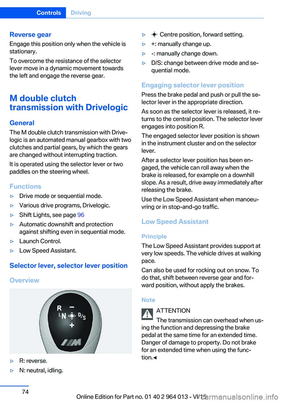
Overview
▷R: reverse.▷N: neutral, idling.▷ Centre position, forward setting.▷+: manually change up.▷-: manually change down.▷D/S: change between drive mode and se‐
quential mode.
Engaging selector lever position
Press the brake pedal and push or pull the se‐
lector lever in the appropriate direction.
As soon as the selector lever is released, it re‐
turns to the central position. The selector lever
engages into position R.
The engaged selector lever position is shown
in the instrument cluster and on the selector
lever.
After a selector lever position has been en‐
gaged, the vehicle can roll away when the
brake is released, for example on a downhill
slope. As a result, drive away immediately after
releasing the brake.
Use the Low Speed Assistant when manoeu‐
vring or in stop-and-go traffic.
Low Speed Assistant
Principle
The Low Speed Assistant provides support at
very low speeds. The vehicle drives at walking
pace.
Can also be used for rocking out on snow. To
do that, shift between reverse gear and for‐
ward position, without apply the brakes.
Note ATTENTION
The transmission can overhead when us‐
ing the function and depressing the brake
pedal at the same time for an extended time.
Danger of damage to property. Do not brake
for an extended time when using the func‐
tion.◀
Seite 74ControlsDriving74
Online Edition for Part no. 01 40 2 964 013 - VI/15
Page 101 of 228
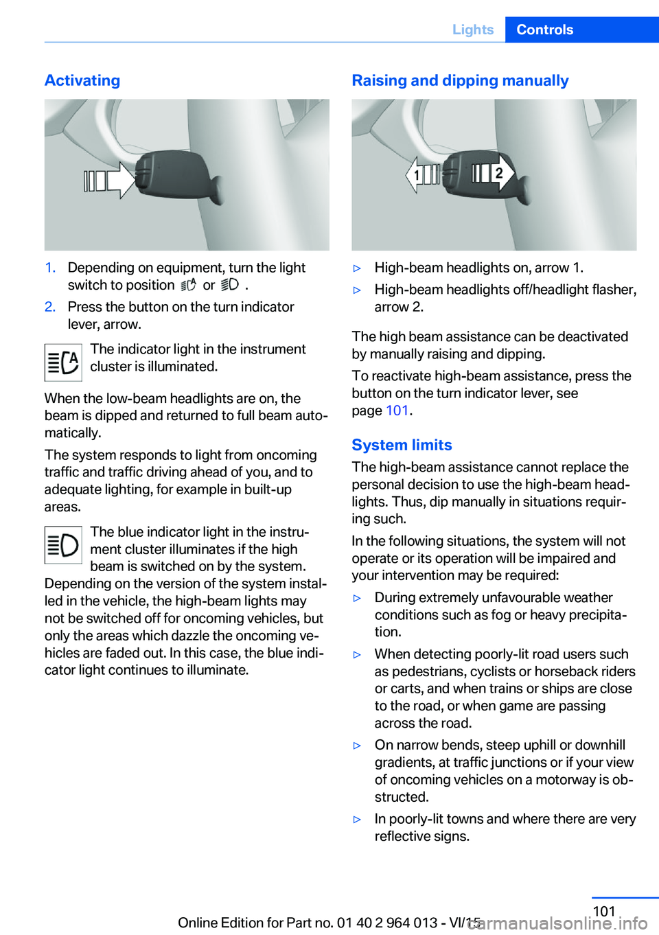
Activating1.Depending on equipment, turn the light
switch to position
or .
2.Press the button on the turn indicator
lever, arrow.
The indicator light in the instrument
cluster is illuminated.
When the low-beam headlights are on, the
beam is dipped and returned to full beam auto‐
matically.
The system responds to light from oncoming
traffic and traffic driving ahead of you, and to
adequate lighting, for example in built-up
areas.
The blue indicator light in the instru‐
ment cluster illuminates if the high
beam is switched on by the system.
Depending on the version of the system instal‐
led in the vehicle, the high-beam lights may
not be switched off for oncoming vehicles, but
only the areas which dazzle the oncoming ve‐
hicles are faded out. In this case, the blue indi‐
cator light continues to illuminate.
Raising and dipping manually▷High-beam headlights on, arrow 1.▷High-beam headlights off/headlight flasher,
arrow 2.
The high beam assistance can be deactivated
by manually raising and dipping.
To reactivate high-beam assistance, press the
button on the turn indicator lever, see
page 101.
System limits
The high-beam assistance cannot replace the
personal decision to use the high-beam head‐
lights. Thus, dip manually in situations requir‐
ing such.
In the following situations, the system will not
operate or its operation will be impaired and
your intervention may be required:
▷During extremely unfavourable weather
conditions such as fog or heavy precipita‐
tion.▷When detecting poorly-lit road users such
as pedestrians, cyclists or horseback riders
or carts, and when trains or ships are close
to the road, or when game are passing
across the road.▷On narrow bends, steep uphill or downhill
gradients, at traffic junctions or if your view
of oncoming vehicles on a motorway is ob‐
structed.▷In poorly-lit towns and where there are very
reflective signs.Seite 101LightsControls101
Online Edition for Part no. 01 40 2 964 013 - VI/15
Page 110 of 228
▷Dynamic driving style, causing the drive
gears to spin, high lateral acceleration.▷Driving with snow chains.
Intelligent Safety
Principle
Intelligent Safety permits central operation of
driver assistance systems.
Depending on equipment, Intelligent Safety
consists of one or more systems which can
help to avoid the risk of a collision. These sys‐
tems are automatically active each time you
start the engine with the start/stop button:
▷Front-end collision warning with city brak‐
ing function, see page 111.▷Person warning, see page 113.
Notes
WARNING
Displays and warnings do not take your
personal responsibility from you. System limi‐
tations can mean that warnings or system re‐
sponses are not issued, are issued too late, or are issued incorrectly. Danger of accidents.
Adapt driving style to the driving conditions.
Observe the traffic situation and intervene ac‐
tively if the situation warrants it.◀
WARNING
Due to system limitations, there may be
malfunctions of individual functions when tow-
starting/towing with activated Intelligent Safety Systems, for example approach control warn‐
ing with light braking function. Danger of acci‐
dents. Switch off all Intelligent Safety Systems
before tow-starting/towing.◀
Overview
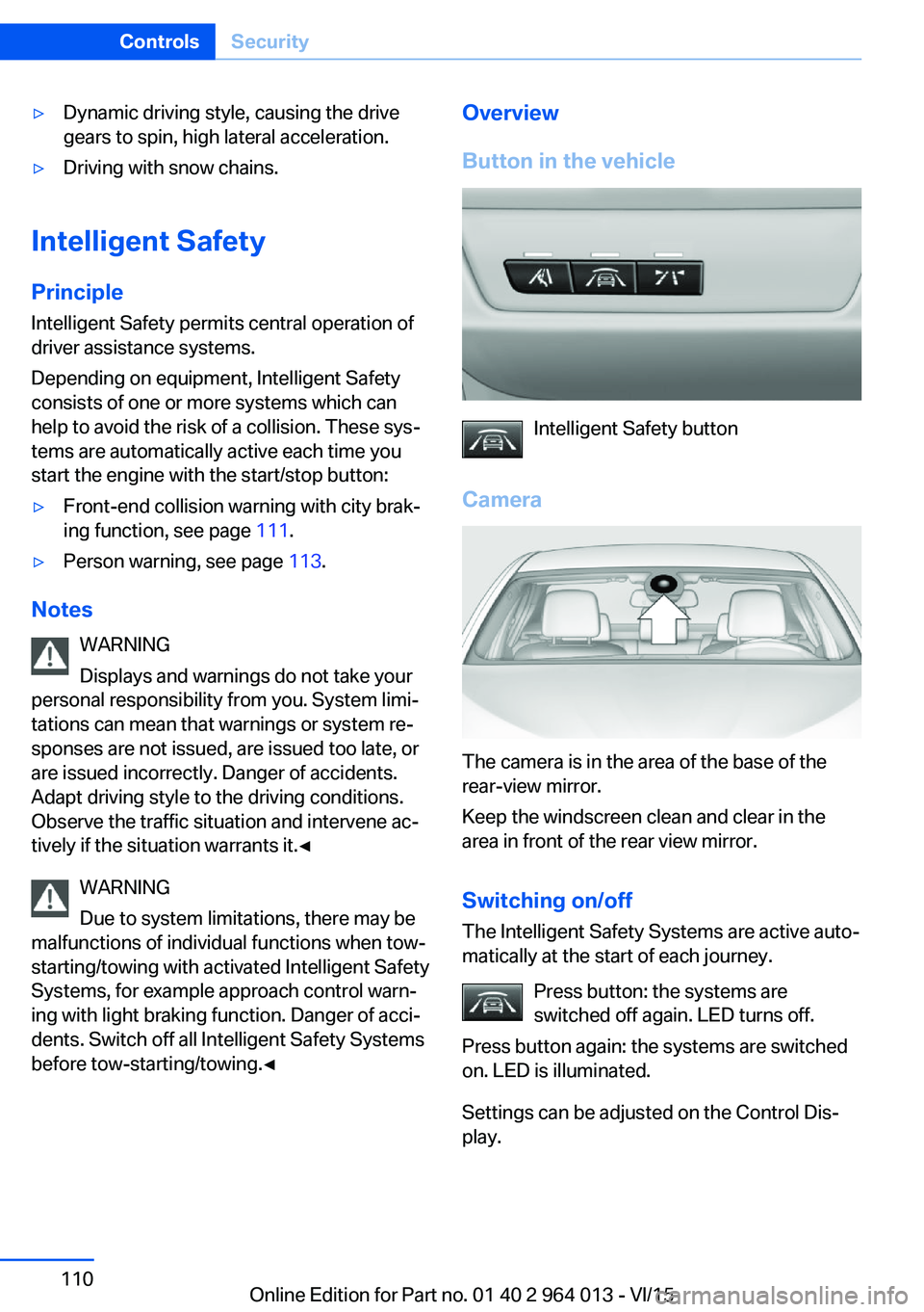
Button in the vehicle
Intelligent Safety button
Camera
The camera is in the area of the base of the
rear-view mirror.
Keep the windscreen clean and clear in the
area in front of the rear view mirror.
Switching on/offThe Intelligent Safety Systems are active auto‐
matically at the start of each journey.
Press button: the systems are
switched off again. LED turns off.
Press button again: the systems are switched
on. LED is illuminated.
Settings can be adjusted on the Control Dis‐
play.
Seite 110ControlsSecurity110
Online Edition for Part no. 01 40 2 964 013 - VI/15
Page 111 of 228
Front-end collision warning
with city braking function
Principle The system can help avoid accidents. If an ac‐
cident cannot be avoided, the system helps to
reduce the collision speed.
The system warns of the possible risk of colli‐
sion and brakes automatically, as necessary.
The automatic braking intervention is done
with limited force and duration.
The system is controlled by a camera in the
area of the rear-view mirror.
The front-end collision warning is also avail‐
able if the Cruise Control is disabled.
When deliberately approaching a vehicle, the
approach control warning and braking inter‐
vention are activated later to avoid unjustified
system responses.
General
The system warns from approximately 5 km/h,
approximately 3 mph in two stages of any risk
of collision with vehicles. The timing of these
warnings may vary depending on the current
driving situation.
Up to approximately 60km/h, 35 mph.
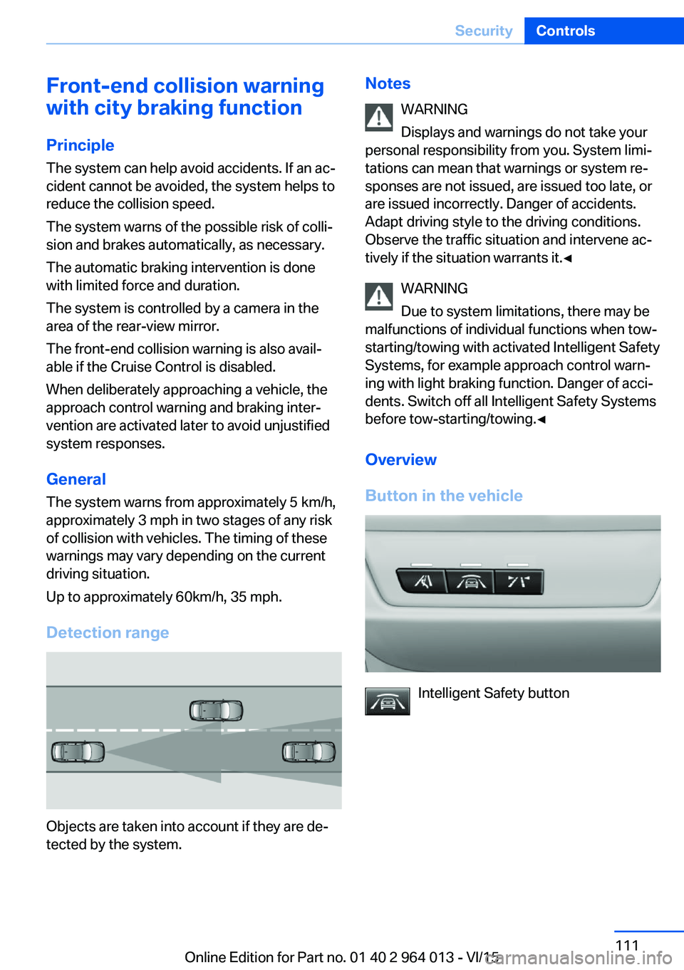
Detection range
Objects are taken into account if they are de‐
tected by the system.
Notes
WARNING
Displays and warnings do not take your
personal responsibility from you. System limi‐
tations can mean that warnings or system re‐
sponses are not issued, are issued too late, or are issued incorrectly. Danger of accidents.
Adapt driving style to the driving conditions.
Observe the traffic situation and intervene ac‐
tively if the situation warrants it.◀
WARNING
Due to system limitations, there may be
malfunctions of individual functions when tow-
starting/towing with activated Intelligent Safety Systems, for example approach control warn‐
ing with light braking function. Danger of acci‐
dents. Switch off all Intelligent Safety Systems
before tow-starting/towing.◀
Overview
Button in the vehicle
Intelligent Safety button
Seite 111SecurityControls111
Online Edition for Part no. 01 40 2 964 013 - VI/15
Page 114 of 228
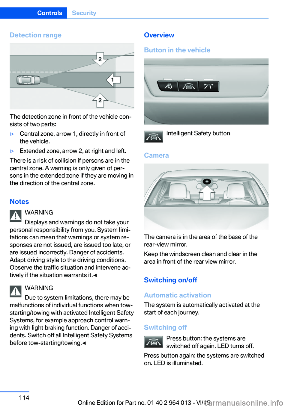
Detection range
The detection zone in front of the vehicle con‐
sists of two parts:
▷Central zone, arrow 1, directly in front of
the vehicle.▷Extended zone, arrow 2, at right and left.
There is a risk of collision if persons are in the
central zone. A warning is only given of per‐
sons in the extended zone if they are moving in
the direction of the central zone.
Notes WARNING
Displays and warnings do not take your
personal responsibility from you. System limi‐
tations can mean that warnings or system re‐
sponses are not issued, are issued too late, or
are issued incorrectly. Danger of accidents.
Adapt driving style to the driving conditions.
Observe the traffic situation and intervene ac‐
tively if the situation warrants it.◀
WARNING
Due to system limitations, there may be
malfunctions of individual functions when tow-
starting/towing with activated Intelligent Safety
Systems, for example approach control warn‐
ing with light braking function. Danger of acci‐
dents. Switch off all Intelligent Safety Systems
before tow-starting/towing.◀
Overview
Button in the vehicle
Intelligent Safety button
Camera
The camera is in the area of the base of the
rear-view mirror.
Keep the windscreen clean and clear in the
area in front of the rear view mirror.
Switching on/off
Automatic activation The system is automatically activated at the
start of each journey.
Switching off Press button: the systems are
switched off again. LED turns off.
Press button again: the systems are switched
on. LED is illuminated.
Seite 114ControlsSecurity114
Online Edition for Part no. 01 40 2 964 013 - VI/15
Page 127 of 228
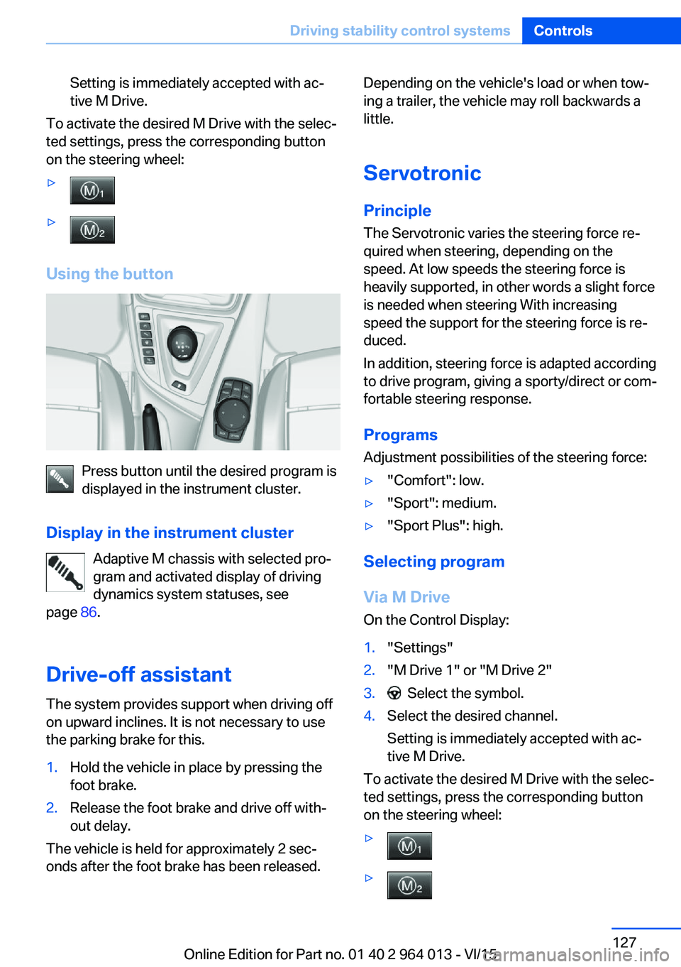
Setting is immediately accepted with ac‐
tive M Drive.
To activate the desired M Drive with the selec‐
ted settings, press the corresponding button
on the steering wheel:
▷▷
Using the button
Press button until the desired program is
displayed in the instrument cluster.
Display in the instrument cluster Adaptive M chassis with selected pro‐
gram and activated display of driving
dynamics system statuses, see
page 86.
Drive-off assistant The system provides support when driving off
on upward inclines. It is not necessary to use
the parking brake for this.
1.Hold the vehicle in place by pressing the
foot brake.2.Release the foot brake and drive off with‐
out delay.
The vehicle is held for approximately 2 sec‐
onds after the foot brake has been released.
Depending on the vehicle's load or when tow‐
ing a trailer, the vehicle may roll backwards a
little.
Servotronic
Principle The Servotronic varies the steering force re‐
quired when steering, depending on the
speed. At low speeds the steering force is
heavily supported, in other words a slight force
is needed when steering With increasing
speed the support for the steering force is re‐
duced.
In addition, steering force is adapted according
to drive program, giving a sporty/direct or com‐
fortable steering response.
Programs Adjustment possibilities of the steering force:▷"Comfort": low.▷"Sport": medium.▷"Sport Plus": high.
Selecting program
Via M Drive On the Control Display:
1."Settings"2."M Drive 1" or "M Drive 2"3. Select the symbol.4.Select the desired channel.
Setting is immediately accepted with ac‐
tive M Drive.
To activate the desired M Drive with the selec‐
ted settings, press the corresponding button
on the steering wheel:
▷▷Seite 127Driving stability control systemsControls127
Online Edition for Part no. 01 40 2 964 013 - VI/15
Page 133 of 228
▷With persons with certain clothing, for ex‐
ample a coat.▷With external disruption to the ultrasound,
for example by passing vehicles or loud
machines.▷If the sensors are dirty, iced-up, damaged
or incorrectly adjusted.▷In certain weather conditions, for example
high humidity, rain, snowfall, extreme heat
or strong wind.▷With trailer noses and tow hitches of other
vehicles.▷With thin or wedge-shaped objects.▷With moving objects.▷For higher, protruding objects, for example
projecting walls or loads.▷For objects with corners and sharp edges.▷For objects with fine surfaces or struc‐
tures, for example fences.▷For objects with porous surfaces.
Low objects already indicated, such as kerbs,
may enter the sensors' blind areas before or
after a continuous tone is given.
False alarms
Under the following conditions, PDC can issue
a warning although there is no obstacle in the
detection range:
▷In heavy rain.▷If the sensors are very dirty or covered with
ice.▷If the sensors are covered with snow.▷On rough road surfaces.▷On uneven ground, for example speed
bumps.▷In large, rectangular buildings with smooth
walls, for example underground car parks.▷In car washes.▷Due to dense exhaust gas.▷Due to other ultrasonic sources, for exam‐
ple sweeping machines, steam-jet cleaners
or neon lights.
The functional disruption is reported by an
alternating continuous tone between the
front and rear loudspeakers. As soon as
the disruption by other ultrasound sources
is no longer present, the system is fully
functional again.
Malfunction
A Check Control message is shown.
The recording area of the sensors is shown
hatched on the Control Display.
PDC has failed. Have the system checked.
Surround view Principle
Surround view contains various camera assis‐
tance systems, providing support when park‐
ing, manoeuvring and exits and junctions with
poor visibility.
▷Rear-view camera, see page 133.▷Side view, see page 136.▷Top view, see page 137.
Rear-view camera
Principle The rear-view camera offers assistance when
reversing into a parking space or manoeuvring.
To achieve this, the area behind the vehicle is
displayed on the Control Display.
Notes WARNING
The system does not take your personal
responsibility from you when you are estimat‐
ing the traffic situation. Danger of accidents.
Adapt driving style to the driving conditions.
Seite 133Driving comfortControls133
Online Edition for Part no. 01 40 2 964 013 - VI/15