ESP BMW M6 COUPE 2010 E63 User Guide
[x] Cancel search | Manufacturer: BMW, Model Year: 2010, Model line: M6 COUPE, Model: BMW M6 COUPE 2010 E63Pages: 250, PDF Size: 8.4 MB
Page 48 of 250
Adjusting
46 The function for automatically calling up
the last seat position is switched on and is
stored for the remote control currently in use.
Switching off automatic call-up
Deactivate "Last seat position auto.".
Front head restraints
A correctly adjusted head restraint reduces the
risk of spinal injury in the event of an accident.
Adjust the head restraint so that its center
is approximately at ear level. Otherwise
there is increased danger of injury in the event
of an accident.Only remove the head restraints
if no one will be sitting on the seat in question.
Reinstall the head restraints before transport-
ing passengers, as otherwise the head restraint
cannot provide its protective function.<
Active front head restraints
In the event of a rear-end collision of sufficient
severity, the active head restraint reduces the
distance to the head.
Do not use seat covers or head restraint
covers that could impede the proper
functioning of the active head restraint. Other-
wise, there is no assurance that the active head
restraint will perform its protective function and
it is not possible to take advantage of its injury-
reducing potential in the event of a rear-end
collision.
Have the active head restraints reset after they
are triggered in a rear-end collision. Only have
this work carried out by a BMW center or a
workshop that works according to BMW repair
procedures with correspondingly trained per-
sonnel. Otherwise, this safety equipment will
not function properly.<
Please contact a BMW center if you wish
to have the front head restraints removed
and installed.<
Coupe
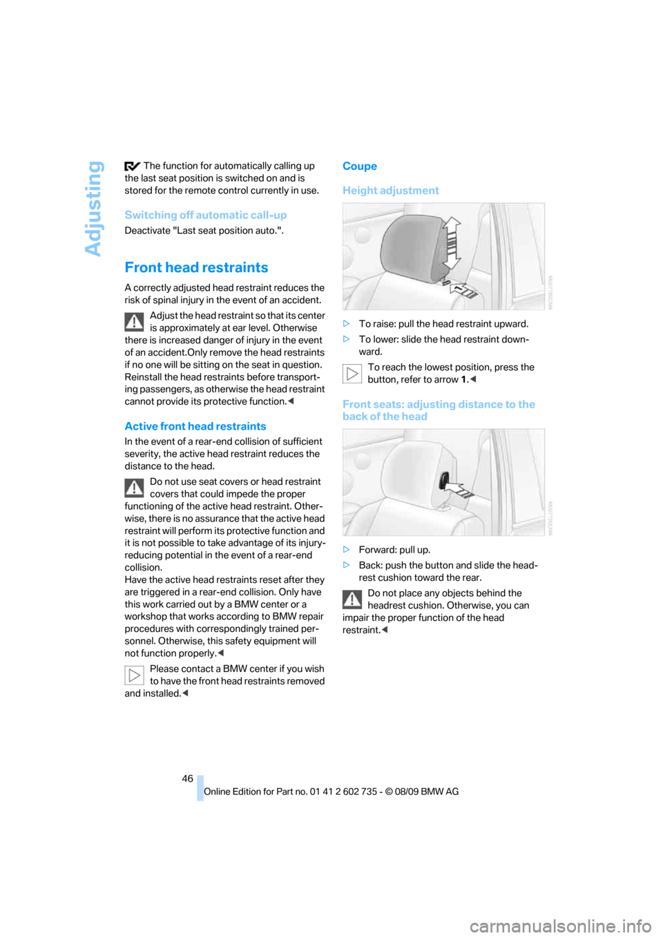
Height adjustment
>To raise: pull the head restraint upward.
>To lower: slide the head restraint down-
ward.
To reach the lowest position, press the
button, refer to arrow 1.<
Front seats: adjusting distance to the
back of the head
>Forward: pull up.
>Back: push the button and slide the head-
rest cushion toward the rear.
Do not place any objects behind the
headrest cushion. Otherwise, you can
impair the proper function of the head
restraint.<
Page 50 of 250
Adjusting
48 Lock backrest warning lamp:
Lights up when the backrest is not
locked. At the same time, a message is
shown on the Control Display.
Safety belts
To ensure that the safety systems con-
tinue to provide optimized protection,
please observe the adjustment instructions on
page43.<
Before every drive, make sure that safety belts
are being worn at all of the occupied seats. Air-
bags complement the safety belt as an addi-
tional safety device, but they do not represent a
substitute.
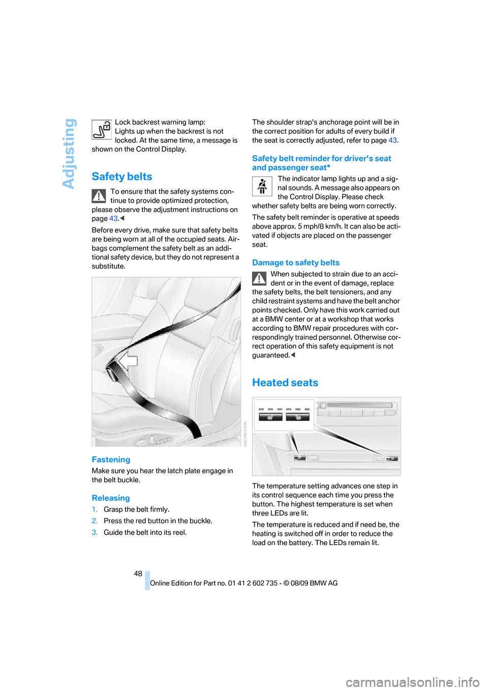
Fastening
Make sure you hear the latch plate engage in
the belt buckle.
Releasing
1.Grasp the belt firmly.
2.Press the red button in the buckle.
3.Guide the belt into its reel.The shoulder strap's anchorage point will be in
the correct position for adults of every build if
the seat is correctly adjusted, refer to page43.
Safety belt reminder for driver's seat
and passenger seat*
The indicator lamp lights up and a sig-
nal sounds. A message also appears on
the Control Display. Please check
whether safety belts are being worn correctly.
The safety belt reminder is operative at speeds
above approx. 5 mph/8 km/h. It can also be acti-
vated if objects are placed on the passenger
seat.
Damage to safety belts
When subjected to strain due to an acci-
dent or in the event of damage, replace
the safety belts, the belt tensioners, and any
child restraint systems and have the belt anchor
points checked. Only have this work carried out
at a BMW center or at a workshop that works
according to BMW repair procedures with cor-
respondingly trained personnel. Otherwise cor-
rect operation of this safety equipment is not
guaranteed.<
Heated seats
The temperature setting advances one step in
its control sequence each time you press the
button. The highest temperature is set when
three LEDs are lit.
The temperature is reduced and if need be, the
heating is switched off in order to reduce the
load on the battery. The LEDs remain lit.
Page 53 of 250
Controls
51Reference
At a glance
Driving tips
Communications
Navigation
Entertainment
Mobility
Drivelogic: shifting modes and Drivel-
ogic driving programs, refer to page59
>"EDC:"
Programs of the Electronic Damping
Control, refer to page79
>"DSC:"
Dynamic Stability Control and
M Dynamic Mode, refer to page76
>"POWER:"
Programs of the M Engine Dynamics
Control, refer to page60
>"Head-Up display"
*
Views of the Head-up Display, refer to
page86
You can reset all settings for MDrive to the
default values:
3.Select the desired function.
4.Press the controller.
5.Turn the controller to select the desired set-
ting.
6.Press the controller.
The setting is stored for the remote control cur-
rently in use.
Activating settings
Press the button on the steering wheel.
The indicator lamp in the instrument
cluster lights up. The settings made on
the Control Display for the functions
contained in MDrive are active.
Pressing the button again deactivates MDrive.
If the indicator lamp flashes after the but-
ton was pressed, MDrive was unable to
respond because the ABS Antilock Brake Sys-
tem or DSC Dynamic Stability Control are cur-
rently regulating driving stability. Press the
button again when the indicator lamp no
longer flashes.<
Even with MDrive activated, you can change
individual settings outside MDrive, e.g. with the
buttons in the center console. To reactivate all
settings made for MDrive on the Control Dis-
play: press the button twice.
Page 54 of 250
Transporting children safely
52
Transporting children safely
The right place for children
Do not leave children unattended in the
vehicle, otherwise they could endanger
themselves and other persons, e.g. by opening
the doors.<
Children always in the rear
Accident research shows that the safest place
for children is on the rear seat.
Children younger than 13 years of age or
with a height under 5 ft/150 cm may only
be transported in the rear in child restraint sys-
tems which correspond to the age, weight and
height of the child. Otherwise there is an
increased danger of injury in an accident.<
Children 13 years of age or older must wear a
safety belt as soon as a suitable child restraint
system can no longer be used due to their age,
size and weight.
Exception for front passenger seat
Should it be necessary to use a child
restraint system on the front passenger
seat, the front and side airbags for the front pas-
senger must be deactivated. Otherwise, a child
traveling on that seat will face a significant risk
of injury if the airbags are deployed, even with a
child restraint system. Before installing a child
restraint system, move the front passenger seat
a s f a r b a c k a n d up a s p o s s i b le t o o b t a i n t h e b e s t
possible position for the belt. Do not change the
seat position after this.<
For more information on automatic deactivation
of the front passenger airbags, refer to page84.
Installing child restraint
systems
Follow child restraint system manufac-
turer's instructions for the selection,
installation and use of child restraint systems. Otherwise, the degree of protection they offer
may be reduced.<
On front passenger seat
After mounting a child restraint system on
the front passenger seat, make sure that
the front and side airbags on the front passen-
ger side are deactivated, as otherwise there is
an increased risk of injury if the airbags are trig-
gered.<
Seat position
Before installing a child restraint system, move
the front passenger seat as far back and up as
possible to obtain the best possible position for
the belt. Do not change the seat position after
this.
Backrest width
Before mounting a child restraint system
on the front passenger seat, the backrest
width adjustment must be completely open.<
1.Adjust the backrest width to the fully open
position, refer to page44.
2.Install child seat.
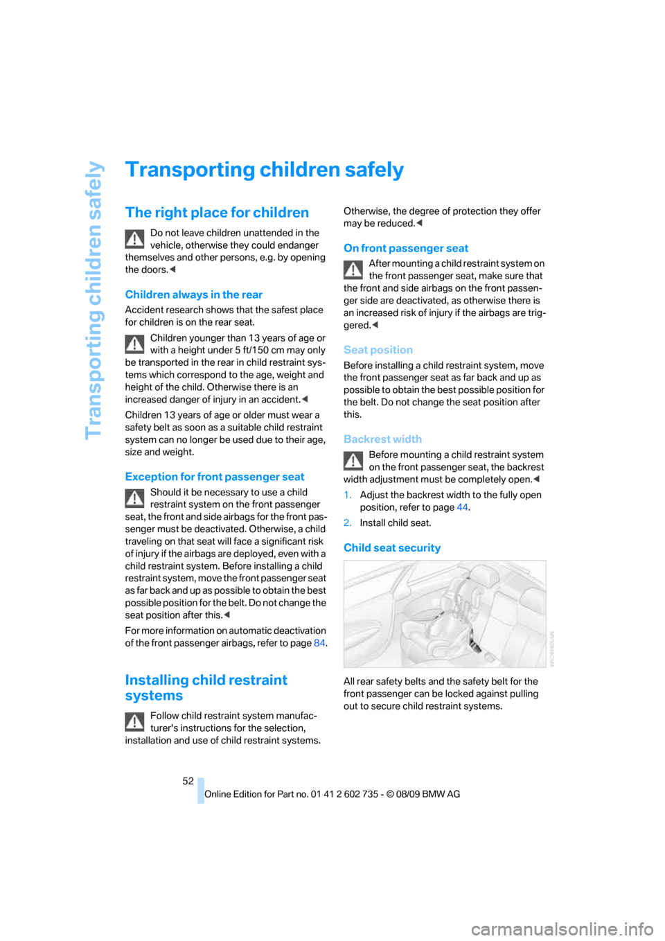
Child seat security
All rear safety belts and the safety belt for the
front passenger can be locked against pulling
out to secure child restraint systems.
Page 61 of 250
Controls
59Reference
At a glance
Driving tips
Communications
Navigation
Entertainment
Mobility
D Drive mode
In the Drive mode, all forward gears are shifted
automatically.
Shifting from Sequential mode to Drive mode:
shift using the shift paddles or the selector
lever, or press the selector level to the right in
the D/S direction.
Shifting back to Drive mode: press the selector
lever to the right in the D/S direction again.
Kickdown: for rapid acceleration, e. g. when
passing, press the accelerator pedal as far
down as it will go. You achieve maximum accel-
eration.
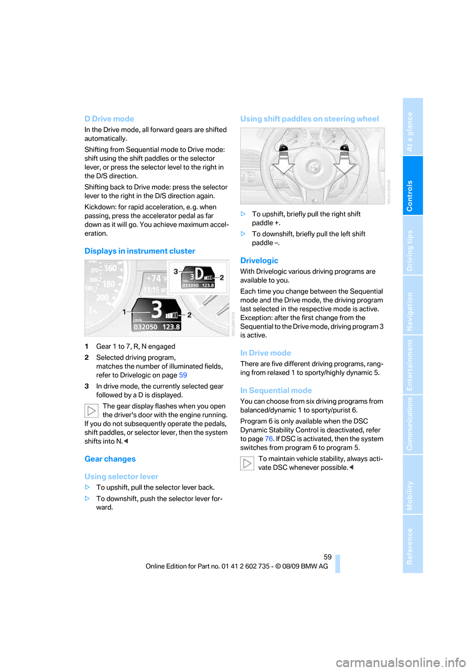
Displays in instrument cluster
1Gear 1 to 7, R, N engaged
2Selected driving program,
matches the number of illuminated fields,
refer to Drivelogic on page59
3In drive mode, the currently selected gear
followed by a D is displayed.
The gear display flashes when you open
the driver's door with the engine running.
If you do not subsequently operate the pedals,
shift paddles, or selector lever, then the system
shifts into N.<
Gear changes
Using selector lever
>To upshift, pull the selector lever back.
>To downshift, push the selector lever for-
ward.
Using shift paddles on steering wheel
>To upshift, briefly pull the right shift
paddle +.
>To downshift, briefly pull the left shift
paddle –.
Drivelogic
With Drivelogic various driving programs are
available to you.
Each time you change between the Sequential
mode and the Drive mode, the driving program
last selected in the respective mode is active.
Exception: after the first change from the
Sequential to the Drive mode, driving program 3
is active.
In Drive mode
There are five different driving programs, rang-
ing from relaxed 1 to sporty/highly dynamic 5.
In Sequential mode
You can choose from six driving programs from
balanced/dynamic 1 to sporty/purist 6.
Program 6 is only available when the DSC
Dynamic Stability Control is deactivated, refer
to page76. If DSC is activated, then the system
switches from program 6 to program 5.
To maintain vehicle stability, always acti-
vate DSC whenever possible.<
Page 63 of 250
Controls
61Reference
At a glance
Driving tips
Communications
Navigation
Entertainment
Mobility
tion is minimal and the engine output is
reduced.
"P 500" program
The "P 500" program provides maximum per-
formance and more spontaneous reaction of
the engine to accelerator pedal movements.
"P 500 Sport" program
In the "P 500 Sport" program, the engine
responds to accelerator pedal movements with
a high degree of spontaneity and uncompro-
mising sportiness while exhibiting maximum
performance.
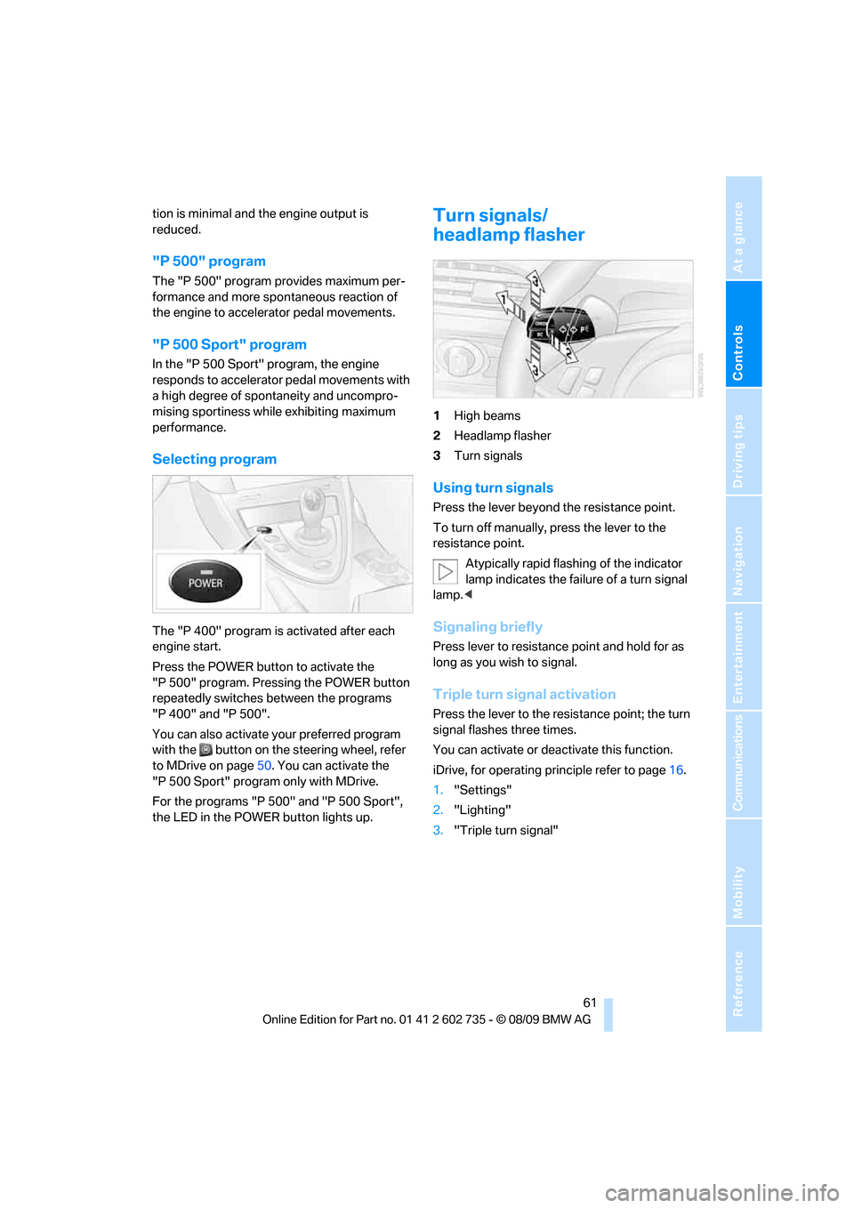
Selecting program
The "P 400" program is activated after each
engine start.
Press the POWER button to activate the
"P 500" program. Pressing the POWER button
repeatedly switches between the programs
"P 400" and "P 500".
You can also activate your preferred program
with the button on the steering wheel, refer
to MDrive on page50. You can activate the
"P 500 Sport" program only with MDrive.
For the programs "P 500" and "P 500 Sport",
the LED in the POWER button lights up.
Turn signals/
headlamp flasher
1High beams
2Headlamp flasher
3Turn signals
Using turn signals
Press the lever beyond the resistance point.
To turn off manually, press the lever to the
resistance point.
Atypically rapid flashing of the indicator
lamp indicates the failure of a turn signal
lamp.<
Signaling briefly
Press lever to resistance point and hold for as
long as you wish to signal.
Triple turn signal activation
Press the lever to the resistance point; the turn
signal flashes three times.
You can activate or deactivate this function.
iDrive, for operating principle refer to page16.
1."Settings"
2."Lighting"
3."Triple turn signal"
Page 69 of 250
Controls
67Reference
At a glance
Driving tips
Communications
Navigation
Entertainment
Mobility
Cruising range
Displays the estimated cruising range available
with the remaining fuel. The range is projected
based on the driving style over the last 20 miles/
30 km.
Refuel as soon as possible once your
cruising range falls below 30 miles/
50 km, otherwise engine functions are not
ensured and damage can occur.<
Average fuel consumption
The average fuel consumption is calculated for
the time during which the engine is running.
To reset average fuel consumption: press BC
button on turn signal lever for approx. 2 sec-
onds.
For different routes
You can display the average speed and average
fuel consumption for two different routes on the
Control Display, refer to the following and to
Trip computer.
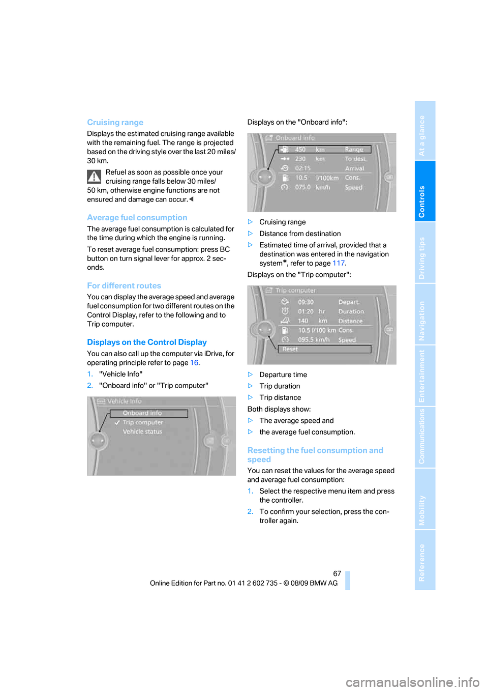
Displays on the Control Display
You can also call up the computer via iDrive, for
operating principle refer to page16.
1."Vehicle Info"
2."Onboard info" or "Trip computer"Displays on the "Onboard info":
>Cruising range
>Distance from destination
>Estimated time of arrival, provided that a
destination was entered in the navigation
system
*, refer to page117.
Displays on the "Trip computer":
>Departure time
>Trip duration
>Trip distance
Both displays show:
>The average speed and
>the average fuel consumption.
Resetting the fuel consumption and
speed
You can reset the values for the average speed
and average fuel consumption:
1.Select the respective menu item and press
the controller.
2.To confirm your selection, press the con-
troller again.
Page 73 of 250
Controls
71Reference
At a glance
Driving tips
Communications
Navigation
Entertainment
Mobility
and warning lamps in the instrument cluster,
and if necessary an acoustic signal and text
messages at the bottom of the Control Display.
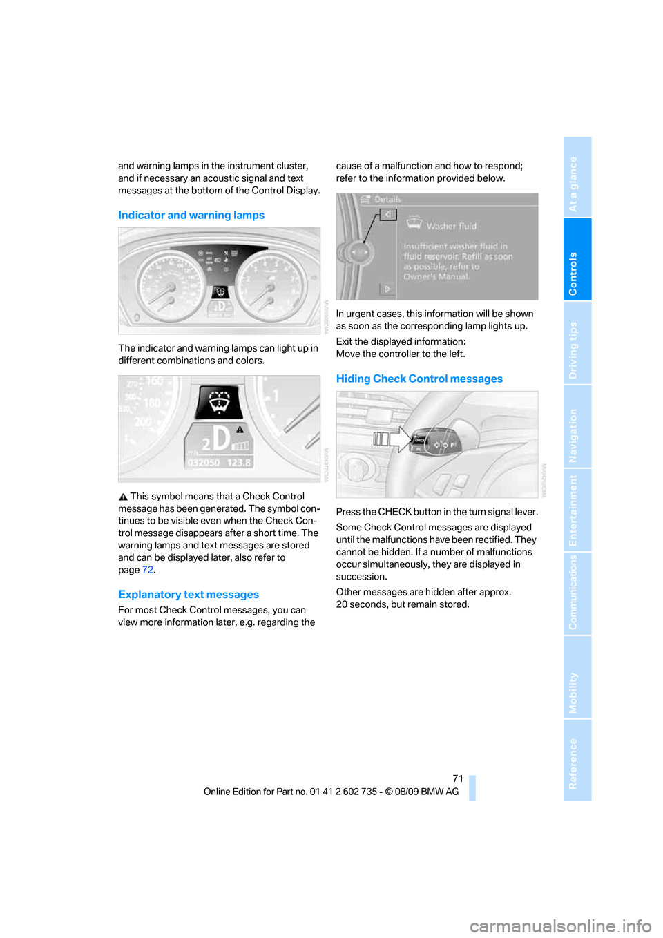
Indicator and warning lamps
The indicator and warning lamps can light up in
different combinations and colors.
This symbol means that a Check Control
message has been generated. The symbol con-
tinues to be visible even when the Check Con-
trol message disappears after a short time. The
warning lamps and text messages are stored
and can be displayed later, also refer to
page72.
Explanatory text messages
For most Check Control messages, you can
view more information later, e.g. regarding the cause of a malfunction and how to respond;
refer to the information provided below.
In urgent cases, this information will be shown
as soon as the corresponding lamp lights up.
Exit the displayed information:
Move the controller to the left.
Hiding Check Control messages
Press the CHECK button in the turn signal lever.
Some Check Control messages are displayed
until the malfunctions have been rectified. They
cannot be hidden. If a number of malfunctions
occur simultaneously, they are displayed in
succession.
Other messages are hidden after approx.
20 seconds, but remain stored.
Page 78 of 250
Technology for comfort, convenience and safety
76 signal tone sounds. The display appears on the
Control Display as soon as PDC is activated.
System limits
Even with PDC, final responsibility for
estimating the distance between the
vehicle and any obstacles always remains with
the driver. Even when sensors are provided,
there is a blind spot in which objects can no
longer be detected. The system is also subject
to the physical limits that apply to all forms of
ultrasonic measurement, such as those
encountered with tow bars and trailer cou-
plings, or thin and wedge-shaped objects etc.
Low objects already displayed, e. g. curbs, can
also disappear from the detection area of the
sensors again before or after a continuous tone
already sounds. Higher, protruding objects, e.g.
ledges, cannot be detected. For this reason,
drive with care; otherwise, there is a danger of
personal injury or property damage.
Loud sources of sound, inside and outside the
vehicle, could drown out the PDC signal tone.<
Driving stability control
systems
Your BMW is equipped with an extended array
of systems designed to enhance and maintain
vehicle stability under extreme conditions.
Antilock Brake System ABS
ABS prevents locking of the wheels during
braking. Safe steering response is maintained
even during full braking. Active safety is thus
increased.
The ABS is operational every time you start the
engine. For information on safe braking, refer to
page109.
CBC Cornering Brake Control
When braking during curves or when braking
during a lane change, driving stability and steer-
ing response are improved further.
Electronic brake-force distribution
The system controls the brake pressure in the
rear wheels to ensure stable braking behavior.
Brake assistant
When you apply the brakes rapidly, this system
produces maximum braking force boosting and
thus helps to achieve the shortest possible
braking distance during full braking maneuvers.
This system exploits all of the benefits provided
by ABS.
Do not reduce the pressure on the brake pedal
for the duration of the full braking.
DSC Dynamic Stability Control
DSC optimizes vehicle stability and traction. It
also detects unstable driving states such as
understeering and oversteering, and helps
keep the vehicle on course within the physical
limits by reducing the engine output and by
braking at the wheels.
The DSC is operational every time you start the
engine.
The laws of physics cannot be repealed,
even with DSC. An appropriate driving
style always remains the responsibility of the
driver. Therefore, do not reduce the additional
safety margin further by taking risks.<
Indicator lamp
The indicator lamp goes out shortly
after the engine is started.
The indicator lamp flashes: DSC con-
trols the drive forces and brake forces.
The indicator lamp stays lit: DSC is deactivated.
M Dynamic Mode MDM
The M Dynamic Mode is a mode of the DSC
Dynamic Stability Control. It enables driving
with greater longitudinal and lateral accelera-
tion on dry road surfaces, however with limited
vehicle stability. The system does not provide
stabilizing intervention by reducing the engine
output and braking at the wheels until the abso-
lute driving limit is reached. Steering correc-
tions by the driver may also be required in this
driving state.
Page 82 of 250
Technology for comfort, convenience and safety
80 In the event of a pressure loss, there is a change
in the rolling circumference and therefore the
rotation speed of the corresponding wheel. The
system detects this change and reports it as a
flat tire.
Functional requirement
The system must have been initialized when the
tire inflation pressure was correct; otherwise,
reliable signaling of a flat tire is not ensured.
The initialization must be repeated after
every correction of the tire inflation pres-
sure and after every tire or wheel change.<
System limits
The Flat Tire Monitor is unable to warn
the driver of sudden, severe tire damage
caused by external factors, nor can it identify
the gradual loss of pressure that will inevitably
occur in all four tires over a lengthy period of
time.<
In the following situations, the system could be
delayed or malfunction:
>System has not been initialized
>Driving on snowy or slippery road surface
>Sporty driving style: slip in the drive wheels,
high lateral acceleration
>Driving with snow chains
*
Initializing system
The initialization finishes during driving,
which can be interrupted at any time.
When driving resumes, the initialization is con-
tinued automatically. The system is initialized
after this activation phase.
The initialization process adopts the set infla-
tion tire pressures as reference values for the
detection of a flat tire. Initialization is started by
confirming the inflation pressures.
The system is not initialized when traveling with
snow chains
*.<
With Sequential Manual Transmission via the
button in the center console:1.Start the engine, but do not start driving.
2.Press the button for approx. 5 seconds.
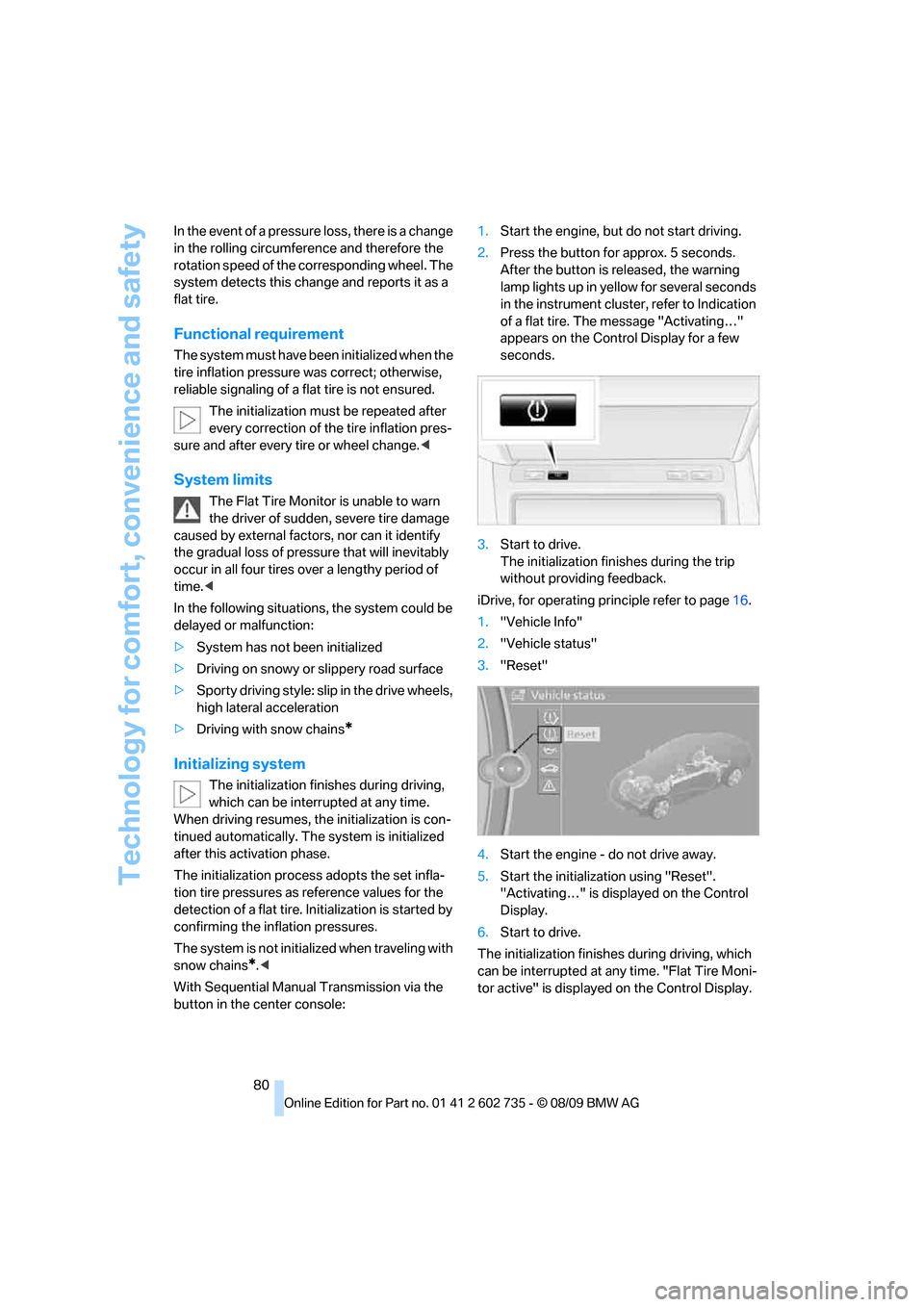
After the button is released, the warning
lamp lights up in yellow for several seconds
in the instrument cluster, refer to Indication
of a flat tire. The message "Activating…"
appears on the Control Display for a few
seconds.
3.Start to drive.
The initialization finishes during the trip
without providing feedback.
iDrive, for operating principle refer to page16.
1."Vehicle Info"
2."Vehicle status"
3."Reset"
4.Start the engine - do not drive away.
5.Start the initialization using "Reset".
"Activating…" is displayed on the Control
Display.
6.Start to drive.
The initialization finishes during driving, which
can be interrupted at any time. "Flat Tire Moni-
tor active" is displayed on the Control Display.