ECU BMW MOTORRAD G650 XMOTO 2007 Rider's Manual (in English)
[x] Cancel search | Manufacturer: BMW MOTORRAD, Model Year: 2007, Model line: G650 XMOTO, Model: BMW MOTORRAD G650 XMOTO 2007Pages: 132, PDF Size: 2.83 MB
Page 41 of 132
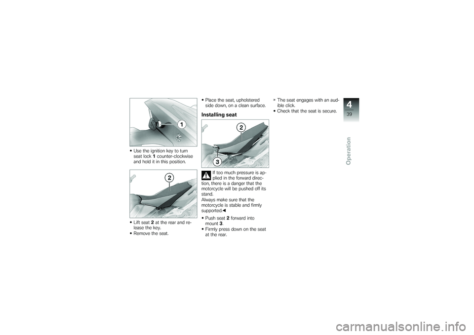
Use the ignition key to turn
seat lock1counter-clockwise
and hold it in this position.
Lift seat 2at the rear and re-
lease the key.
Remove the seat. Place the seat, upholstered
side down, on a clean surface.
Installing seat
If too much pressure is ap-
plied in the forward direc-
tion, there is a danger that the
motorcycle will be pushed off its
stand.
Always make sure that the
motorcycle is stable and firmly
supported.
Push seat 2forward into
mount 3.
Firmly press down on the seat
at the rear. The seat engages with an aud-
ible click.
Check that the seat is secure.
439zOperation
Page 46 of 132
ChecklistUse the following checklist to
check important functions, set-
tings and wear limits before you
ride off.Brakes
Brake-fluid levels, front and rear
Clutch
Clutch fluid level
Shock absorber setting and
spring preload
Tyre-tread depth and tyre
pressures
Cases correctly installed and
luggage secured
At regular intervals: Engine oil level (every refuelling
stop)
Brake-pad wear (every third
refuelling stop)
Tension and lubrication of the
drive chain
StartingSide standYou cannot start the motorcycle
with the side stand extended and
a gear engaged. The engine will
switch itself off if you start it with
the gearbox in neutral and then
engage a gear before retracting
the side stand.GearboxYou can start the engine when
the gearbox is in neutral or if you
pull the clutch with a gear en-
gaged.
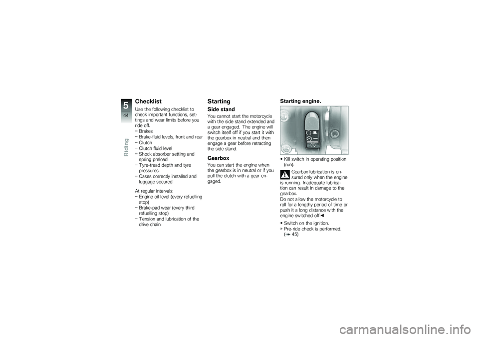
Starting engine.Kill switch in operating position
(run).
Gearbox lubrication is en-
sured only when the engine
is running. Inadequate lubrica-
tion can result in damage to the
gearbox.
Do not allow the motorcycle to
roll for a lengthy period of time or
push it a long distance with the
engine switched off.
Switch on the ignition.
Pre-ride check is performed.
( 45)
544zRiding
Page 74 of 132
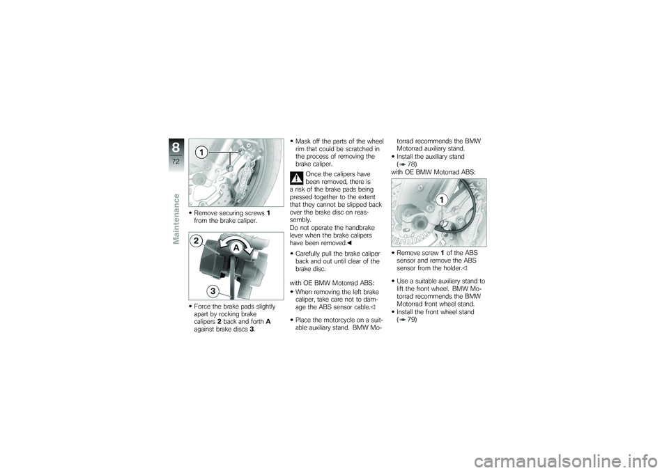
Remove securing screws1
from the brake caliper.
Force the brake pads slightly
apart by rocking brake
calipers 2back and forth A
against brake discs 3. Mask off the parts of the wheel
rim that could be scratched in
the process of removing the
brake caliper.
Once the calipers have
been removed, there is
a risk of the brake pads being
pressed together to the extent
that they cannot be slipped back
over the brake disc on reas-
sembly.
Do not operate the handbrake
lever when the brake calipers
have been removed.
Carefully pull the brake caliper
back and out until clear of the
brake disc.
with OE BMW Motorrad ABS: When removing the left brake
caliper, take care not to dam-
age the ABS sensor cable.
Place the motorcycle on a suit-
able auxiliary stand. BMW Mo- torrad recommends the BMW
Motorrad auxiliary stand.
Install the auxiliary stand
( 78)
with OE BMW Motorrad ABS:
Remove screw 1of the ABS
sensor and remove the ABS
sensor from the holder.
Use a suitable auxiliary stand to
lift the front wheel. BMW Mo-
torrad recommends the BMW
Motorrad front wheel stand.
Install the front wheel stand
( 79)
872zMaintenance
Page 76 of 132
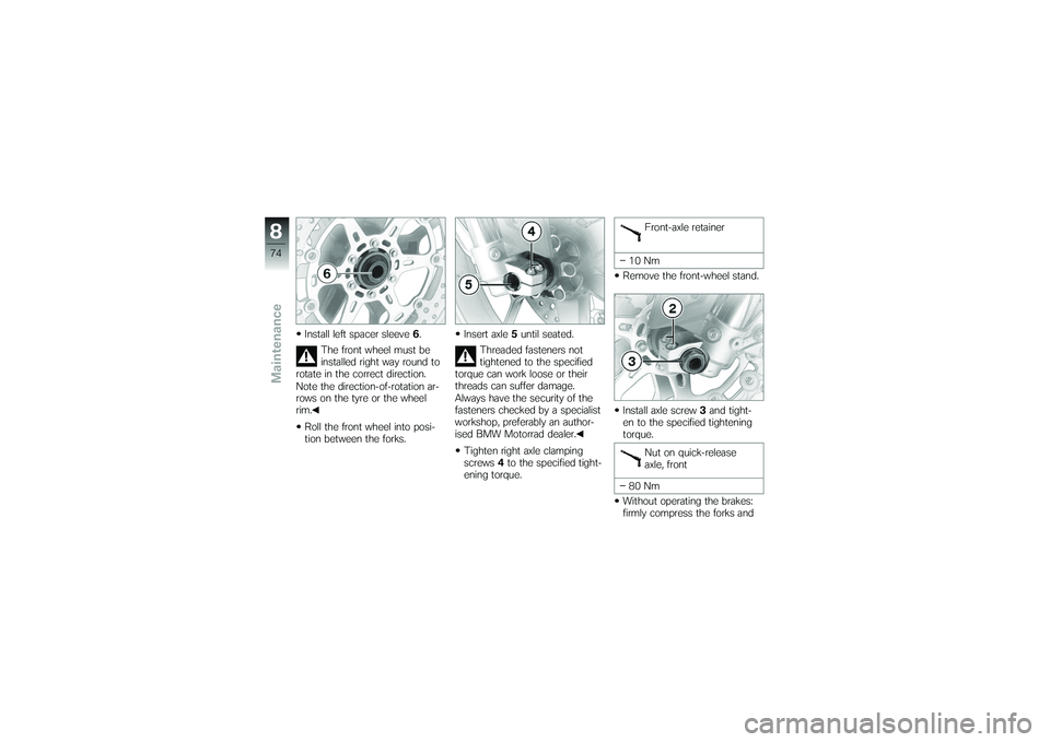
Install left spacer sleeve6.
The front wheel must be
installed right way round to
rotate in the correct direction.
Note the direction-of-rotation ar-
rows on the tyre or the wheel
rim.
Roll the front wheel into posi-
tion between the forks. Insert axle
5until seated.
Threaded fasteners not
tightened to the specified
torque can work loose or their
threads can suffer damage.
Always have the security of the
fasteners checked by a specialist
workshop, preferably an author-
ised BMW Motorrad dealer.
Tighten right axle clamping
screws 4to the specified tight-
ening torque. Front-axle retainer
10 Nm
Remove the front-wheel stand.
Install axle screw 3and tight-
en to the specified tightening
torque.
Nut on quick-release
axle, front
80 Nm
Without operating the brakes:
firmly compress the forks and
874zMaintenance
Page 77 of 132
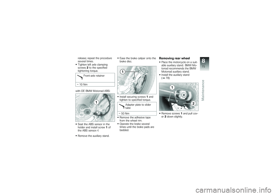
release; repeat the procedure
several times.
Tighten left axle clamping
screws2to the specified
tightening torque.
Front-axle retainer
10 Nm
with OE BMW Motorrad ABS:
Seat the ABS sensor in the
holder and install screw 1of
the ABS sensor.
Remove the auxiliary stand. Ease the brake caliper onto the
brake disc.
Install securing screws
1and
tighten to specified torque.
Adapter plate to slider
tube
50 Nm
Remove the adhesive tape
from the wheel rim.
Operate the brake several
times until the brake pads are
bedded.
Removing rear wheelPlace the motorcycle on a suit-
able auxiliary stand. BMW Mo-
torrad recommends the BMW
Motorrad auxiliary stand.
Install the auxiliary stand
( 78)
875zMaintenance
Remove screws 1and pull cov-
er 2down slightly.
Page 82 of 132
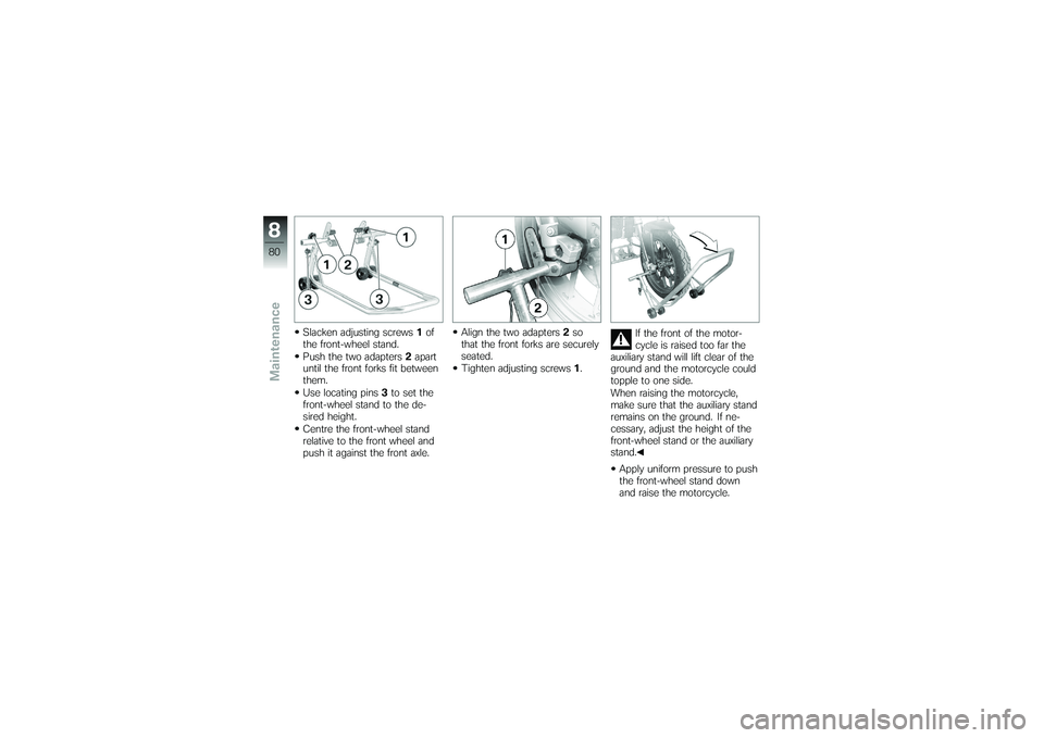
Slacken adjusting screws1of
the front-wheel stand.
Push the two adapters 2apart
until the front forks fit between
them.
Use locating pins 3to set the
front-wheel stand to the de-
sired height.
Centre the front-wheel stand
relative to the front wheel and
push it against the front axle. Align the two adapters
2so
that the front forks are securely
seated.
Tighten adjusting screws 1. If the front of the motor-
cycle is raised too far the
auxiliary stand will lift clear of the
ground and the motorcycle could
topple to one side.
When raising the motorcycle,
make sure that the auxiliary stand
remains on the ground. If ne-
cessary, adjust the height of the
front-wheel stand or the auxiliary
stand.
Apply uniform pressure to push
the front-wheel stand down
and raise the motorcycle.
880zMaintenance
Page 83 of 132
FusesRemoving fuse
Risk of fire if an attempt is
made to jumper defective
fuse.
Always replace defective fuses
with new fuses of the correct
amperage rating.
Switch off the ignition.
Remove the seat ( 38)
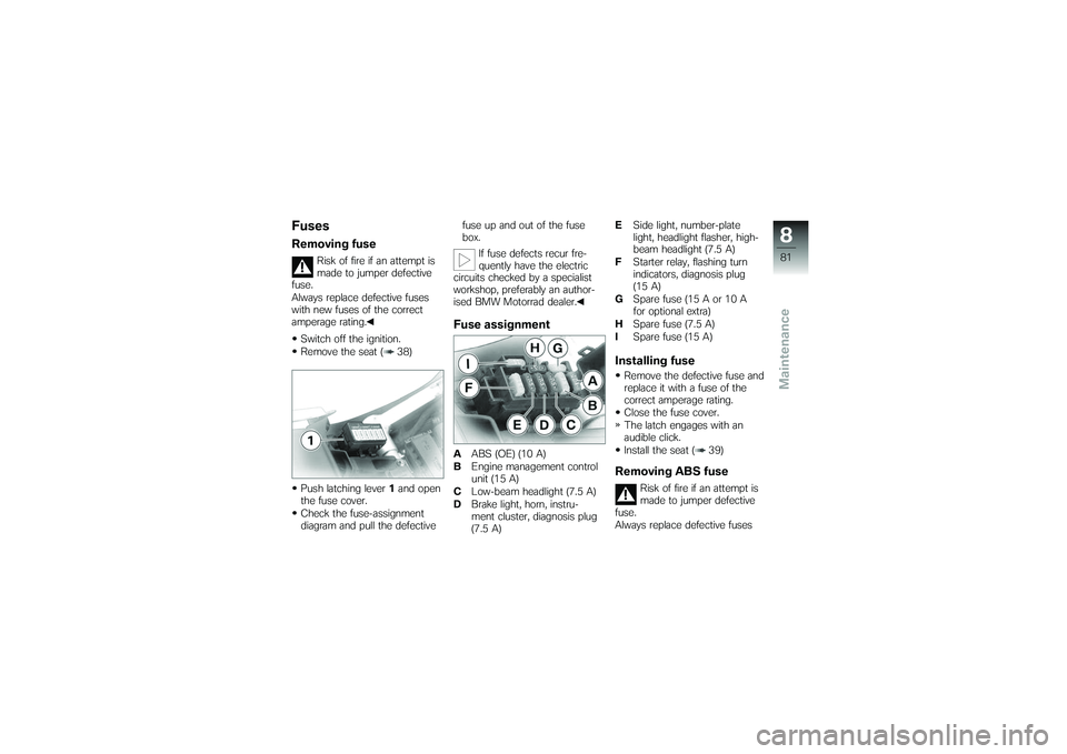
Push latching lever 1and open
the fuse cover.
Check the fuse-assignment
diagram and pull the defective fuse up and out of the fuse
box.
If fuse defects recur fre-
quently have the electric
circuits checked by a specialist
workshop, preferably an author-
ised BMW Motorrad dealer.
Fuse assignmentA ABS (OE) (10 A)
B Engine management control
unit (15 A)
C Low-beam headlight (7.5 A)
D Brake light, horn, instru-
ment cluster, diagnosis plug
(7.5 A) E
Side light, number-plate
light, headlight flasher, high-
beam headlight (7.5 A)
F Starter relay, flashing turn
indicators, diagnosis plug
(15 A)
G Spare fuse (15 A or 10 A
for optional extra)
H Spare fuse (7.5 A)
I Spare fuse (15 A)
Installing fuseRemove the defective fuse and
replace it with a fuse of the
correct amperage rating.
Close the fuse cover.
The latch engages with an
audible click.
Install the seat ( 39)Removing ABS fuse
Risk of fire if an attempt is
made to jumper defective
fuse.
Always replace defective fuses
881zMaintenance
Page 84 of 132
with new fuses of the correct
amperage rating.Switch off the ignition.
Remove the right side panel
( 93)
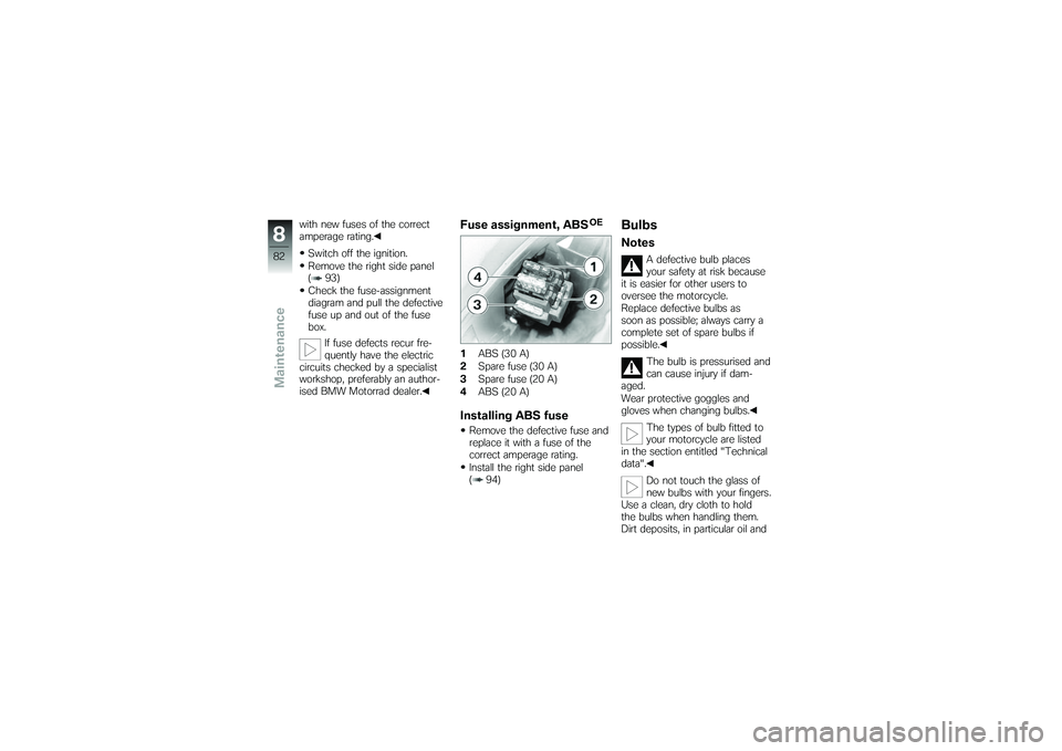
Check the fuse-assignment
diagram and pull the defective
fuse up and out of the fuse
box. If fuse defects recur fre-
quently have the electric
circuits checked by a specialist
workshop, preferably an author-
ised BMW Motorrad dealer.
Fuse assignment, ABS
OE
1 ABS (30 A)
2 Spare fuse (30 A)
3 Spare fuse (20 A)
4 ABS (20 A)Installing ABS fuseRemove the defective fuse and
replace it with a fuse of the
correct amperage rating.
Install the right side panel
( 94)
BulbsNotes
A defective bulb places
your safety at risk because
it is easier for other users to
oversee the motorcycle.
Replace defective bulbs as
soon as possible; always carry a
complete set of spare bulbs if
possible.
The bulb is pressurised and
can cause injury if dam-
aged.
Wear protective goggles and
gloves when changing bulbs.
The types of bulb fitted to
your motorcycle are listed
in the section entitled "Technical
data".
Do not touch the glass of
new bulbs with your fingers.
Use a clean, dry cloth to hold
the bulbs when handling them.
Dirt deposits, in particular oil and
882zMaintenance