tow BMW MOTORRAD K 1200 GT 2007 Rider's Manual (in English)
[x] Cancel search | Manufacturer: BMW MOTORRAD, Model Year: 2007, Model line: K 1200 GT, Model: BMW MOTORRAD K 1200 GT 2007Pages: 173, PDF Size: 2.82 MB
Page 4 of 173
Table of ContentsYou can also consult the index at
the end of this Rider's Manual if
you want to find a particular topic
or item of information.
1 General instructions . . . . . 5
Overview ...................... 6
Abbreviations and symbols . . . . 6
Equipment . . . . . . .............. 7
Technical data . . .............. 7
Currency . ..................... 7
2 General views . . . . . . . . . . . . . 9
General view, left side . . . . . . . . 11
General view, right side . . . . . . 13
Underneath the seat ......... 15
Handlebar fitting, left ......... 16
Handlebar fitting, right . . . . . . . . 17
Instrument cluster . . . ......... 18
Headlight . .................... 19 3 Status indicators . . . . . . . 21
Standard status
indicators .
.................... 22
Status indicators with on-
board computer
OE
........... 23
Status indicators with
tyre-pressure monitoring
(RDC)
OE...................... 24
Status indicators with seat
heatingOE
.................... 24
Telltale light with cruise con-
trol
OE
........................ 25
Standard warnings . . ......... 25
Warnings issued by the on-
board computer
OE
........... 30
ABS warnings . . . ............. 32
ASC warnings
OE
............. 34
RDC warnings
OE
............. 36
Anti-theft alarm
warnings
OE................... 41 4 Operation . . . . . . . . . . . . . . . . 45
Ignition switch and steering
lock . .
........................ 47
Electronic immobiliser . . . . . . . . 48
Clock . . . . . .................... 49
Odometer and tripmeters . . . . 49
Multifunction display ......... 51
On-board computer
OE
....... 51
Tyre pressure monitoring
RDC
OE
....................... 54
Lights . . . . .................... 55
Turn indicators . . ............. 56
Hazard warning flashers . . . . . . 57
Emergency off switch (kill
switch) . . . .................... 58
Grip heating
OE
............... 59
Seat heatingOE............... 60
Automatic Stability Control
ASC
OE
....................... 61
Seat height . . . . . . ............. 62
Windscreen . . . . . ............. 63
Cruise-control system
OE
..... 63
Stowage compartment . . . . . . . 66
Clutch . . . . .................... 66
Page 15 of 173
General view, right side1Fuel filler neck ( 87)
2 Adjustable handlebars
( 67)
3 Brake-fluid reservoir, front
( 111)
4 Adjuster for headlight beam
throw (underneath the in-
strument cluster) ( 73)
5 Stowage compartment
( 66)
6 Vehicle identification num-
ber
213zGeneral views
Page 47 of 173
Operation
Operation
Ignition switch and steering lock..... 47
Electronic immobiliser . . . ............ 48
Clock ................................ 49
Odometer and tripmeters ............ 49
Multifunction display ................. 51
On-board computer
OE
............... 51
Tyre pressure monitoring
RDC
OE
.............................. 54
Lights ................................ 55
Turn indicators ....................... 56
Hazard warning flashers . . ............ 57
Emergency off switch (kill switch) . . . . 58
Grip heating
OE
....................... 59
Seat heatingOE
...................... 60 Automatic Stability Control
ASC
OE
.............................. 61
Seat height . . . ....................... 62
Windscreen . . . ....................... 63
Cruise-control system
OE
............. 63
Stowage compartment . ............. 66
Clutch . . ............................. 66
Brakes . . ............................. 67
Handlebars . . . ....................... 67
Mirrors . . ............................. 68
Spring preload ....................... 68
Damping ............................. 69
Electronic Suspension Adjustment
ESA
OE
............................... 69
Tyres . . . ............................. 72
445zOperation
Page 68 of 173

Stowage compartmentOpening stowage
compartmentUse the ignition key to turn
lock barrel2to right angles
with the forward direction of
travel.
Lock of the stowage compart-
ment unlocked.
Push the lock barrel in.
Lid 1pops up.
Closing stowage
compartmentSnap lid 1closed and push it
down.
The lock engages with an aud-
ible click.
Use the ignition key to turn
lock barrel 2in line with the
forward direction of travel.
Lock of the stowage compart-
ment locked.
ClutchAdjusting clutch lever
If the position of the clutch
fluid reservoir is changed,
air can enter the clutch system.
Do not twist the handlebar fitting
or the handlebars.
Attempting to adjust the
clutch lever while riding the
motorcycle can lead to accidents.
Do not attempt to adjust the
clutch lever unless the motor-
cycle is at a standstill.
Turn adjuster Ato position 1:
466zOperation
Page 101 of 173
the on-board power supply sys-
tem is minimised, the supply to
the power socket is cut off ap-
proximately 15 minutes after the
ignition is switched off, and it is
also temporarily interrupted dur-
ing the start procedure.Cable routingThe cables from the power sock-
et to the auxiliary device must be
routed in such a way that they:Do not impede the rider
Do not restrict or obstruct the
steering angle and handling
characteristics
Cannot be trapped
Incorrectly routed cables
can impede the rider.
Route the cables as described
above.
LuggageCorrect loading
Overloading and imbal-
anced loads can adversely
affect the motorcycle's handling.
Do not exceed the permissible
gross weight and be sure to
comply with the instructions on
loading.
Set spring preload, damping
characteristic and tyre pres-
sures to suit total weight.
Adjust the spring preload for
rear wheel ( 68)
Check the tyre pressure
( 72)
Adjust the damping for rear
wheel ( 69)
Ensure that the case volumes
on the left and right are equal.
Make sure that the weight is
uniformly distributed between
right and left. Pack heavy items at the bot-
tom and toward the inboard
side.
Note the maximum permissible
payload of the cases and the
speed limit for riding with cases
on the motorcycle.
Payload of cases
8kg Maximum permissible
speed for riding with
cases fitted to the motorcycle
180 km/h
Note the maximum permiss-
ible payload of the topcase and
the speed limit for riding with a
topcase on the motorcycle.
Payload of topcase
with OA Topcase:
799zAccessories
Page 112 of 173
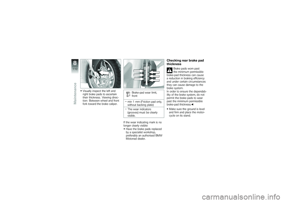
Visually inspect the left and
right brake pads to ascertain
their thickness. Viewing direc-
tion: Between wheel and front
fork toward the brake caliper.Brake-pad wear limit,
front
min 1 mm (Friction pad only,
without backing plate)
The wear indicators
(grooves) must be clearly
visible.
If the wear indicating mark is no
longer clearly visible: Have the brake pads replaced
by a specialist workshop,
preferably an authorised BMW
Motorrad dealer.
Checking rear brake pad
thickness
Brake pads worn past
the minimum permissible
brake-pad thickness can cause
a reduction in braking efficiency
and under certain circumstances
they can cause damage to the
brake system.
In order to ensure the dependab-
ility of the brake system, do not
permit the brake pads to wear
past the minimum permissible
brake-pad thickness.
Make sure the ground is level
and firm and place the motor-
cycle on its stand.
8110zMaintenance
Page 121 of 173
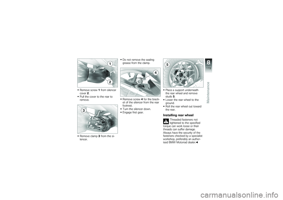
Remove screw1from silencer
cover 2.
Pull the cover to the rear to
remove.
Remove clamp 3from the si-
lencer. Do not remove the sealing
grease from the clamp.
Remove screw
4for the brack-
et of the silencer from the rear
footrest.
Turn the silencer down.
Engage first gear. Place a support underneath
the rear wheel and remove
studs
5.
Lower the rear wheel to the
ground.
Roll the rear wheel out toward
the rear.
Installing rear wheel
Threaded fasteners not
tightened to the specified
torque can work loose or their
threads can suffer damage.
Always have the security of the
fasteners checked by a specialist
workshop, preferably an author-
ised BMW Motorrad dealer.
8119zMaintenance
Page 170 of 173
Seat, 15Adjust the seat height, 62
Seat heating, 60
Seat lock, 11
Seats Install the front seat, 75
Install the rear seat, 75
Remove the front seat, 74
Remove the rear seat, 73
Service, 156 Status indicators on the
display, 22
Service Card, 156
Side stand For starting, 80
Spark plugs, 151
Speedometer, 18
Spring preload Adjusting for rear wheel, 68
Spring preload, rear Adjusting, 11
Starter, 17
Starting, 80 Steering lock
Locking, 48
Stowage compartment, 13, 66
Suspension damping, rear Adjusting, 11
T
Technical data Battery, 151
Brakes, 149
Bulbs, 151
Clutch, 147
Dimensions, 152
Electrics, 150
Engine, 145
Engine oil, 146
Frame, 152
Fuel, 146
Rear-wheel drive, 148
Running gear, 148
Spark plugs, 151
Standards, 7
Transmission, 147
Weights, 153 Wheels and tyres, 149
Telltale lights, 18
Toolkit, 15 Service kit, 106
Standard kit, 106
Topcase Closing, 102
Installing, 103
Opening, 102
Removing, 103
Torques, 141
Transmission For starting, 80
Technical data, 147
Troubleshooting chart, 142
Turn indicators Left, 16
Right, 17
Switching off, 17, 57
Switching on left, 56
Switching on right, 57
12168zIndex