valve BMW X5 2002 E53 M54 Engine Workshop Manual
[x] Cancel search | Manufacturer: BMW, Model Year: 2002, Model line: X5, Model: BMW X5 2002 E53Pages: 48, PDF Size: 2.52 MB
Page 1 of 48
Initial Print Date: 02/2000Revision Date: 6/2000
Subject Page
M54 Engine
Introduction . . . . . . . . . . . . . . . . . . . . . . . . . . . . . . . . . . . . . . . . . . . . . . . . . 2
Mechanical changes . . . . . . . . . . . . . . . . . . . . . . . . . . . . . . . . . . . . . . . . . . . . 4
Performance Charts . . . . . . . . . . . . . . . . . . . . . . . . . . . . . . . . . . . . . . . . . . . . 6
Review Questions. . . . . . . . . . . . . . . . . . . . . . . . . . . . . . . . . . . . . . . . . . . . . . 7
Siemen’s MS 43.0 System
• Introduction . . . . . . . . . . . . . . . . . . . . . . . . . . . . . . . . . . . . . . . . . . . . . . 8
• I - P - O . . . . . . . . . . . . . . . . . . . . . . . . . . . . . . . . . . . . . . . . . . . . . . . . 9
MS 43.0 New functions
• Electronic throttle Control . . . . . . . . . . . . . . . . . . . . . . . . . . . . . . . . . .10
• Accelerator Pedal Sensor (PWG) . . . . . . . . . . . . . . . . . . . . . . . . . . . . .11
• Electronic Throttle Valve (EDK) . . . . . . . . . . . . . . . . . . . . . . . . . . . . . .13
• Main Relay Monitor . . . . . . . . . . . . . . . . . . . . . . . . . . . . . . . . . . . . . . . .15
• Engine Optimized Ignition Key OFF . . . . . . . . . . . . . . . . . . . . . . . . . . . .16
• Diagnosis Module Tank Leakage (DM-TL) . . . . . . . . . . . . . . . . . . . . . . .17
• DM-TL Function . . . . . . . . . . . . . . . . . . . . . . . . . . . . . . . . . . . . . . . . . .18
• DM-TL Test Procedure . . . . . . . . . . . . . . . . . . . . . . . . . . . . . . . . . . . . .20
Carry Over Functions
Inputs
• Oxygen Sensor . . . . . . . . . . . . . . . . . . . . . . . . . . . . . . . . . . . . . . . . . .25
• Camshaft Sensors . . . . . . . . . . . . . . . . . . . . . . . . . . . . . . . . . . . . . . . .26
• Crankshaft Sensor . . . . . . . . . . . . . . . . . . . . . . . . . . . . . . . . . . . . . . . .27
• Misfire Detection . . . . . . . . . . . . . . . . . . . . . . . . . . . . . . . . . . . . . . . . .28
• OBD Fault Codes . . . . . . . . . . . . . . . . . . . . . . . . . . . . . . . . . . . . . . . .30
• Mass Air Meter . . . . . . . . . . . . . . . . . . . . . . . . . . . . . . . . . . . . . . . . . .31
Outputs
• VANOS Control . . . . . . . . . . . . . . . . . . . . . . . . . . . . . . . . . . . . . . . . . .33
• Electric Fan . . . . . . . . . . . . . . . . . . . . . . . . . . . . . . . . . . . . . . . . . . . . .36
• Secondary Air Injection . . . . . . . . . . . . . . . . . . . . . . . . . . . . . . . . . . . .37
• Engine Speed Limit . . . . . . . . . . . . . . . . . . . . . . . . . . . . . . . . . . . . . . .39
• RZV Ignition . . . . . . . . . . . . . . . . . . . . . . . . . . . . . . . . . . . . . . . . . . . .40
• Resonance - Turbulence Manifold . . . . . . . . . . . . . . . . . . . . . . . . . . . .42
• Idle Speed control . . . . . . . . . . . . . . . . . . . . . . . . . . . . . . . . . . . . . . . .45
• Cruise Control . . . . . . . . . . . . . . . . . . . . . . . . . . . . . . . . . . . . . . . . . . .46
• Purge Control . . . . . . . . . . . . . . . . . . . . . . . . . . . . . . . . . . . . . . . . . . . .47
Table of Contents
Page 4 of 48
M54 ENGINE
Mechanical Changes
In addition to the increased displacement of the M54B30 engine, several mechanical
changes were incorporated into the engine for reduced emissions and increased fuel econ-
omy. These changes include:
• NEW PISTONS - The piston has a shorter skirt compared to the M52 TU and continues
with the graphite coating for friction and emission reducing measures. The piston rings have
been modified to reduce friction.
• CRANKSHAFT - The crankshaft for the 3 liter M54 is adopted from the S52B32 - M3
engine.
• CAMSHAFT - The camshaft for the 3 liter M54 is modified with more lift (9.7 mm) and
new valve springs to accommodate the increased lift.
• INTAKE MANIFOLD - The intake manifold is modified with shorter ram tubes (20mm
shorter on 3 liter. The diameter of the tubes is increased slightly.
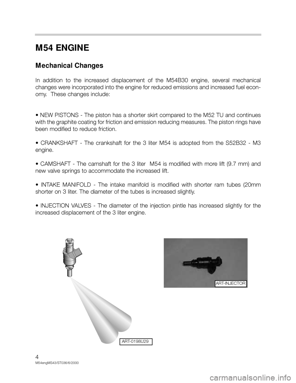
• INJECTION VALVES - The diameter of the injection pintle has increased slightly for the
increased displacement of the 3 liter engine.
4
M54engMS43/ST036/6/2000
ART-0198U29
ART-INJECTOR
Page 5 of 48
M54 ENGINE
MECHANICAL CHANGES
NON RETURN FUEL RAIL SYSTEM
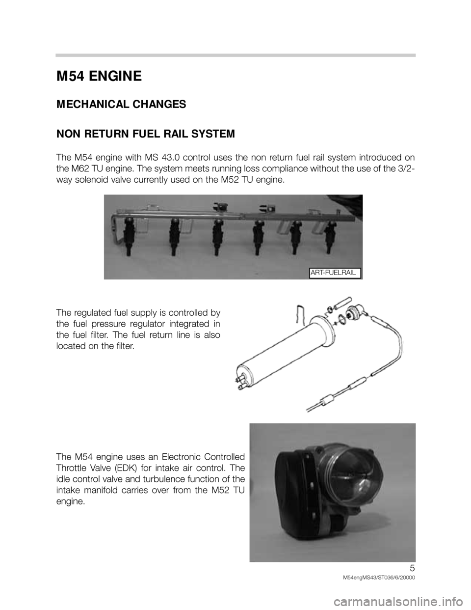
The M54 engine with MS 43.0 control uses the non return fuel rail system introduced on
the M62 TU engine. The system meets running loss compliance without the use of the 3/2-
way solenoid valve currently used on the M52 TU engine.
The regulated fuel supply is controlled by
the fuel pressure regulator integrated in
the fuel filter. The fuel return line is also
located on the filter.
The M54 engine uses an Electronic Controlled
Throttle Valve (EDK) for intake air control. The
idle control valve and turbulence function of the
intake manifold carries over from the M52 TU
engine.
5
M54engMS43/ST036/6/20000
ART-FUELRAIL
Page 8 of 48
8
M54engMS43/ST036/6/2000
SIEMENS ENGINE MANAGEMENT SYSTEM
Models: E53 X5
SOP: 3 liter - 4/00
Objectives of the Module:
At the end of this section of the handout you will be able to:
• Identify the changes that have occurred to the MS 43 system compared to the MS 42
• Describe the operation of the new inputs
• Describe the operation of the new outputs
• Discuss which new components/subsystems relate directly to ULEV compliancy
This new generation Siemens system is designated as
MS 43.0.
Siemens MS 43.0 is a newly developed engine management system to meet the needs of
Ultra Low Emission Vehicle (ULEV) compliancy and continuing with present systems is also
OBD II compliant. This system also includes control of the Motor-driven Throttle Valve
(EDK).
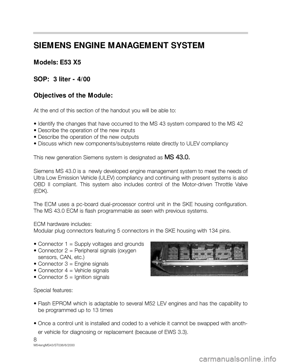
The ECM uses a pc-board dual-processor control unit in the SKE housing configuration.
The MS 43.0 ECM is flash programmable as seen with previous systems.
ECM hardware includes:
Modular plug connectors featuring 5 connectors in the SKE housing with 134 pins.
• Connector 1 = Supply voltages and grounds
• Connector 2 = Peripheral signals (oxygen
sensors, CAN, etc.)
• Connector 3 = Engine signals
• Connector 4 = Vehicle signals
• Connector 5 = Ignition signals
Special features:
• Flash EPROM which is adaptable to several M52 LEV engines and has the capability to
be programmed up to 13 times
• Once a control unit is installed and coded to a vehicle it cannot be swapped with anoth-
er vehicle for diagnosing or replacement (because of EWS 3.3).
Page 10 of 48
10
M54engMS43/ST036/6/2000
MS 43 NEW FUNCTIONS
ELECTRONIC THROTTLE SYSTEM - EML
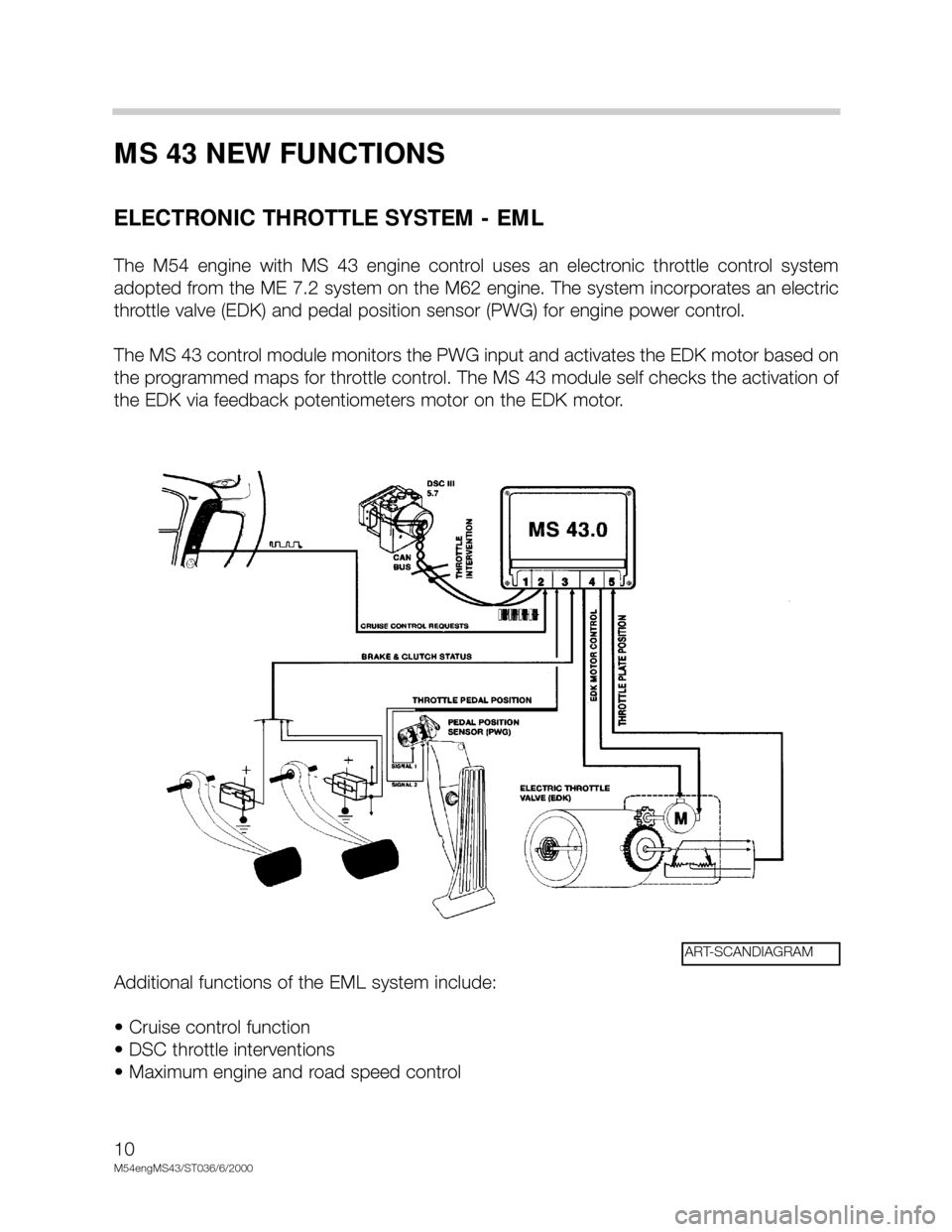
The M54 engine with MS 43 engine control uses an electronic throttle control system
adopted from the ME 7.2 system on the M62 engine. The system incorporates an electric
throttle valve (EDK) and pedal position sensor (PWG) for engine power control.
The MS 43 control module monitors the PWG input and activates the EDK motor based on
the programmed maps for throttle control. The MS 43 module self checks the activation of
the EDK via feedback potentiometers motor on the EDK motor.
Additional functions of the EML system include:
• Cruise control function
• DSC throttle interventions
• Maximum engine and road speed control
ART-SCANDIAGRAM
Page 18 of 48
18
M54engms43/STO36/6/00
123
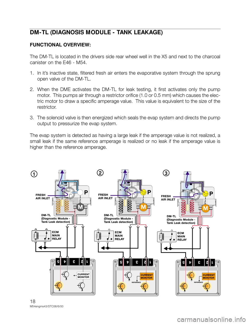
DM-TL (DIAGNOSIS MODULE - TANK LEAKAGE)
FUNCTIONAL OVERVIEW:
The DM-TL is located in the drivers side rear wheel well in the X5 and next to the charcoal
canister on the E46 - M54.
1. In it’s inactive state, filtered fresh air enters the evaporative system through the sprung
open valve of the DM-TL.
2. When the DME activates the DM-TL for leak testing, it first activates only the pump
motor. This pumps air through a restrictor orifice (1.0 or 0.5 mm) which causes the elec-
tric motor to draw a specific amperage value. This value is equivalent to the size of the
restrictor.
3. The solenoid valve is then energized which seals the evap system and directs the pump
output to pressurize the evap system.
The evap system is detected as having a large leak if the amperage value is not realized, a
small leak if the same reference amperage is realized or no leak if the amperage value is
higher than the reference amperage.
Page 19 of 48
19
M54engMS43/ST039/3/17/00
DM-TL (DIAGNOSIS MODULE - TANK LEAKAGE)
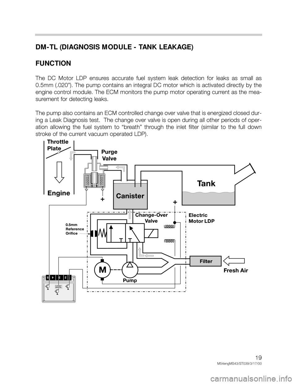
FUNCTION
The DC Motor LDP ensures accurate fuel system leak detection for leaks as small as
0.5mm (.020”). The pump contains an integral DC motor which is activated directly by the
engine control module. The ECM monitors the pump motor operating current as the mea-
surement for detecting leaks.
The pump also contains an ECM controlled change over valve that is energized closed dur-
ing a Leak Diagnosis test. The change over valve is open during all other periods of oper-
ation allowing the fuel system to “breath” through the inlet filter (similar to the full down
stroke of the current vacuum operated LDP).
Page 22 of 48
22
M54engMS43/ST039/3/17/00
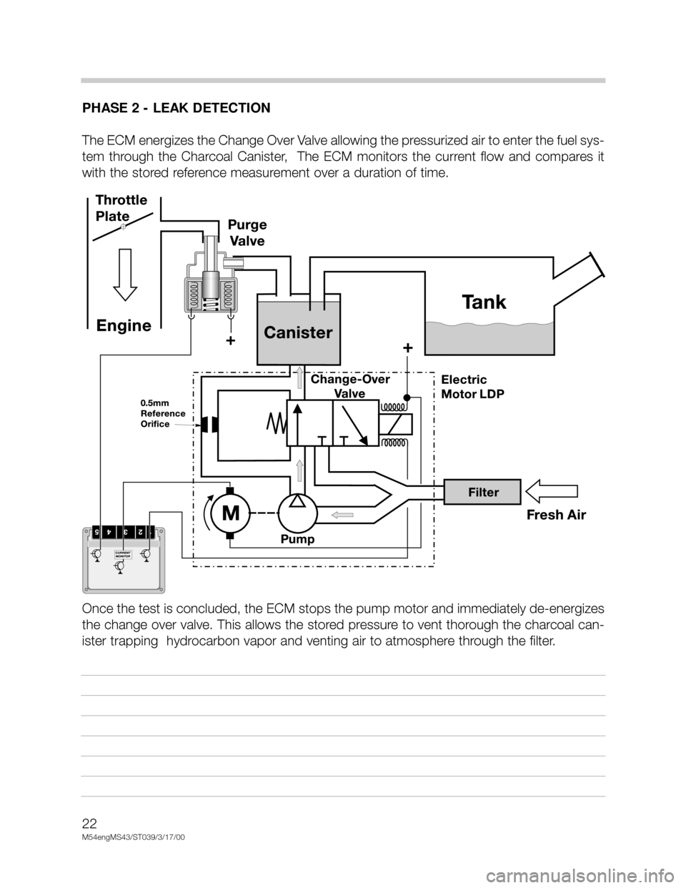
PHASE 2 - LEAK DETECTION
The ECM energizes the Change Over Valve allowing the pressurized air to enter the fuel sys-
tem through the Charcoal Canister, The ECM monitors the current flow and compares it
with the stored reference measurement over a duration of time.
Once the test is concluded, the ECM stops the pump motor and immediately de-energizes
the change over valve. This allows the stored pressure to vent thorough the charcoal can-
ister trapping hydrocarbon vapor and venting air to atmosphere through the filter.
Page 32 of 48
32
M54engMS43/ST036/6/2000
MS 43 CARRY OVER FUNCTIONS
OUTPUT FUNCTIONS -VANOS CONTROL
With the double VANOS system, the valve timing is changed on both the intake and the
exhaust camshafts.
Double VANOS provides the following benefits:
• Torque increase in the low to mid (1500 - 2000 RPM) range without power loss in the
upper RPM range.
• Less incomplete combustion when idling due to less camshaft overlap (also improves
idle speed characteristics).
• Internal exhaust gas recirculation (EGR) in the part load range (reduces NOx and post-
combustion of residual gasses in the exhaust)
• Rapid catalyst warm up and lower “raw” emissions after cold start.
• Reduction in fuel consumption
Double VANOS consists of the following parts:
• Intake and exhaust camshafts with helical gear insert
• Sprockets with adjustable gears
• VANOS actuators for each camshaft
• 2 three-way solenoid switching valves
• 2 impulse wheels for detecting camshaft position
• 2 camshaft position sensors (Hall effect)
The “initial” timing is set by gear positioning (refer to the Repair Instructions for details) and
the chain tensioner. As with the previous VANOS, the hydraulically controlled actuators
move the helical geared cups to regulate camshaft timing. The angled teeth of the helical
gears cause the pushing
movement of the helical cup to be converted into a rotational
movement. This rotational movement is added to the turning of the camshafts and cause
the camshafts to “advance” or “retard”. The adjustment rate is dependent oil temperature,
oil pressure, and engine RPM.
Page 35 of 48
35
M54engMS43/ST036/6/20000
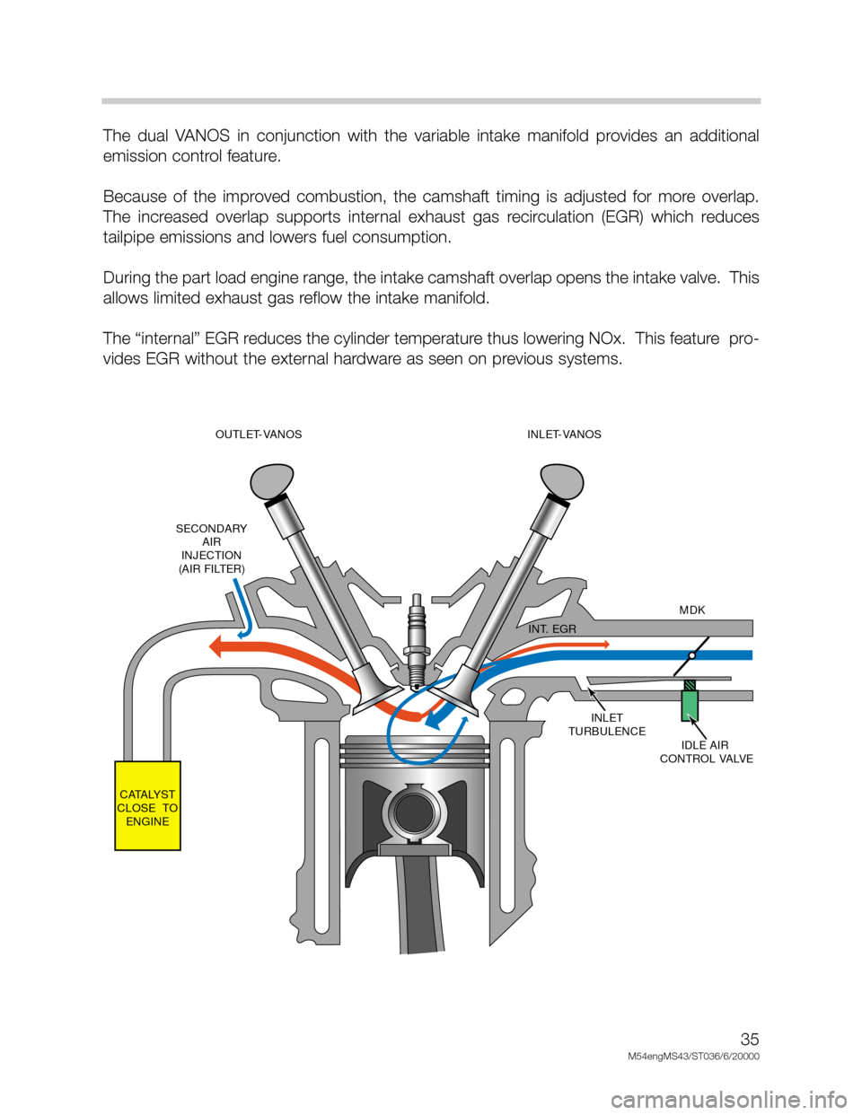
The dual VANOS in conjunction with the variable intake manifold provides an additional
emission control feature.
Because of the improved combustion, the camshaft timing is adjusted for more overlap.
The increased overlap supports internal exhaust gas recirculation (EGR) which reduces
tailpipe emissions and lowers fuel consumption.
During the part load engine range, the intake camshaft overlap opens the intake valve. This
allows limited exhaust gas reflow the intake manifold.
The “internal” EGR reduces the cylinder temperature thus lowering NOx. This feature pro-
vides EGR without the external hardware as seen on previous systems.
INLET
TURBULENCE
IDLE AIR
CONTROL VALVEMDK
INT. EGR
CATALYST
CLOSE TO
ENGINESECONDARY
AIR
INJECTION
(AIR FILTER)OUTLET-VANOS
(228/80-105)INLET-VANOS
(228/80-120)