check engine light BMW X5 2002 E53 M54 Engine Workshop Manual
[x] Cancel search | Manufacturer: BMW, Model Year: 2002, Model line: X5, Model: BMW X5 2002 E53Pages: 48, PDF Size: 2.52 MB
Page 14 of 48

14
M54engMS43/ST036/6/2000
MS 43 NEW FUNCTIONS
EDK THROTTLE POSITION FEEDBACK SIGNALS
EDK FEEDBACK SIGNAL MONITORING & EDK FAILSAFE OPERATION:
• The EDK provides two separate signals from two integral potentiometers (Pot 1 and Pot
2) representing the exact position of the throttle plate.
• EDK Pot 1 provides the primary throttle plate position feedback. As a redundant safe-
ty feature, Pot 2 is continuously cross checked with Pot 1 for signal plausibility.
• If plausibility errors are detected between Pot 1 and Pot 2, MS 43.0 will calculate the
inducted engine air mass (from HFM signal) and only utilize the potentiometer signal that
closely matches the detected intake air mass.
- The MS 43.0 uses the air mass signalling as a “virtual potentiometer” (pot 3) for a
comparative source to provide failsafe operation.
- If MS 43.0 cannot calculate a plausible conclusion from the monitored pots (1 or 2
and virtual 3) the EDK motor is switched off and fuel injection cut out is activated
(no failsafe operation possible).
• The EDK is continuously monitored during all phases of engine operation. It is also
briefly activated when KL 15 is initially switched on as a “pre-flight check” to verify it’s
mechanical integrity (no binding, appropriate return spring tension, etc). This is accom-
plished by monitoring both the motor control amperage and the reaction speed of the
EDK feedback potentiometers. If faults are detected the EDK motor is switched off and
fuel injection cut off is activated (no failsafe operation possible). The engine does how-
ever continue to run extremely rough at idle speed.
• When a replacement EDK is installed, the MS 43.0 adapts to the new component
(required amperage draw for motor control, feedback pot tolerance differences, etc).
This occurs immediately after the next cycle of KL 15 for approximately 30 seconds.
During this period of adaptation, the maximum opening of the throttle plate is 25%.
_____________________________________________________________________________
_____________________________________________________________________________
_____________________________________________________________________________
_____________________________________________________________________________
Page 38 of 48

38
M54engMS43/ST036/6/2000
The Secondary Air Injection System is monitored via the use of the pre-catalyst oxygen sen-
sor(s). Once the air pump is active and is air injected into the system the signal at the oxy-
gen sensor will reflect a lean condition. If the oxygen sensor signal does not change with-
in a predefined time a fault will be set and identify the faulty bank(s). If after completing the
next cold start and a fault is again present the "Service Engine Soon" light will be illuminat-
ed.
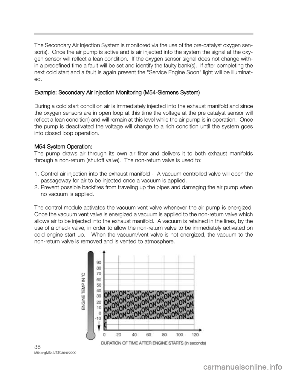
Example: Secondary Air Injection Monitoring (M54-Siemens System)
During a cold start condition air is immediately injected into the exhaust manifold and since
the oxygen sensors are in open loop at this time the voltage at the pre catalyst sensor will
reflect a lean condition) and will remain at this level while the air pump is in operation. Once
the pump is deactivated the voltage will change to a rich condition until the system goes
into closed loop operation.
M54 System Operation:
The pump draws air through its own air filter and delivers it to both exhaust manifolds
through a non-return (shutoff valve). The non-return valve is used to:
1. Control air injection into the exhaust manifold - A vacuum controlled valve will open the
passageway for air to be injected once a vacuum is applied.
2. Prevent possible backfires from traveling up the pipes and damaging the air pump when
no vacuum is applied.
The control module activates the vacuum vent valve whenever the air pump is energized.
Once the vacuum vent valve is energized a vacuum is applied to the non-return valve which
allows air to be injected into the exhaust manifold. A vacuum is retained in the lines, by the
use of a check valve, in order to allow the non-return valve to be immediately activated on
cold engine start up. When the vacuum/vent valve is not energized, the vacuum to the
non-return valve is removed and is vented to atmosphere.