active BMW X5 2014 F15 User Guide
[x] Cancel search | Manufacturer: BMW, Model Year: 2014, Model line: X5, Model: BMW X5 2014 F15Pages: 265, PDF Size: 6.2 MB
Page 60 of 265
Mirrors
Exterior mirrors
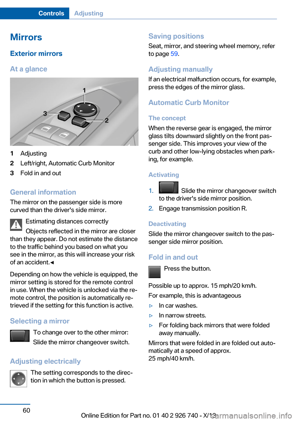
At a glance1Adjusting2Left/right, Automatic Curb Monitor3Fold in and out
General information
The mirror on the passenger side is more
curved than the driver's side mirror.
Estimating distances correctly
Objects reflected in the mirror are closer
than they appear. Do not estimate the distance
to the traffic behind you based on what you
see in the mirror, as this will increase your risk
of an accident.◀
Depending on how the vehicle is equipped, the
mirror setting is stored for the remote control
in use. When the vehicle is unlocked via the re‐
mote control, the position is automatically re‐
trieved if the setting for this function is active.
Selecting a mirror To change over to the other mirror:Slide the mirror changeover switch.
Adjusting electrically The setting corresponds to the direc‐
tion in which the button is pressed.
Saving positions
Seat, mirror, and steering wheel memory, refer
to page 59.
Adjusting manually If an electrical malfunction occurs, for example,
press the edges of the mirror glass.
Automatic Curb Monitor The concept
When the reverse gear is engaged, the mirror
glass tilts downward slightly on the front pas‐
senger side. This improves your view of the
curb and other low-lying obstacles when park‐
ing, for example.
Activating1. Slide the mirror changeover switch
to the driver's side mirror position.2.Engage transmission position R.
Deactivating
Slide the mirror changeover switch to the pas‐
senger side mirror position.
Fold in and out Press the button.
Possible up to approx. 15 mph/20 km/h.
For example, this is advantageous
▷In car washes.▷In narrow streets.▷For folding back mirrors that were folded
away manually.
Mirrors that were folded in are folded out auto‐
matically at a speed of approx.
25 mph/40 km/h.
Seite 60ControlsAdjusting60
Online Edition for Part no. 01 40 2 926 740 - X/13
Page 67 of 265
DrivingVehicle equipment
All standard, country-specific and optional
equipment that is offered in the model series is
described in this chapter. Therefore, equip‐
ment is also described that is not available in a
vehicle, e. g., because of the selected optional
equipment or country variant. This also applies
for safety-related functions and systems.
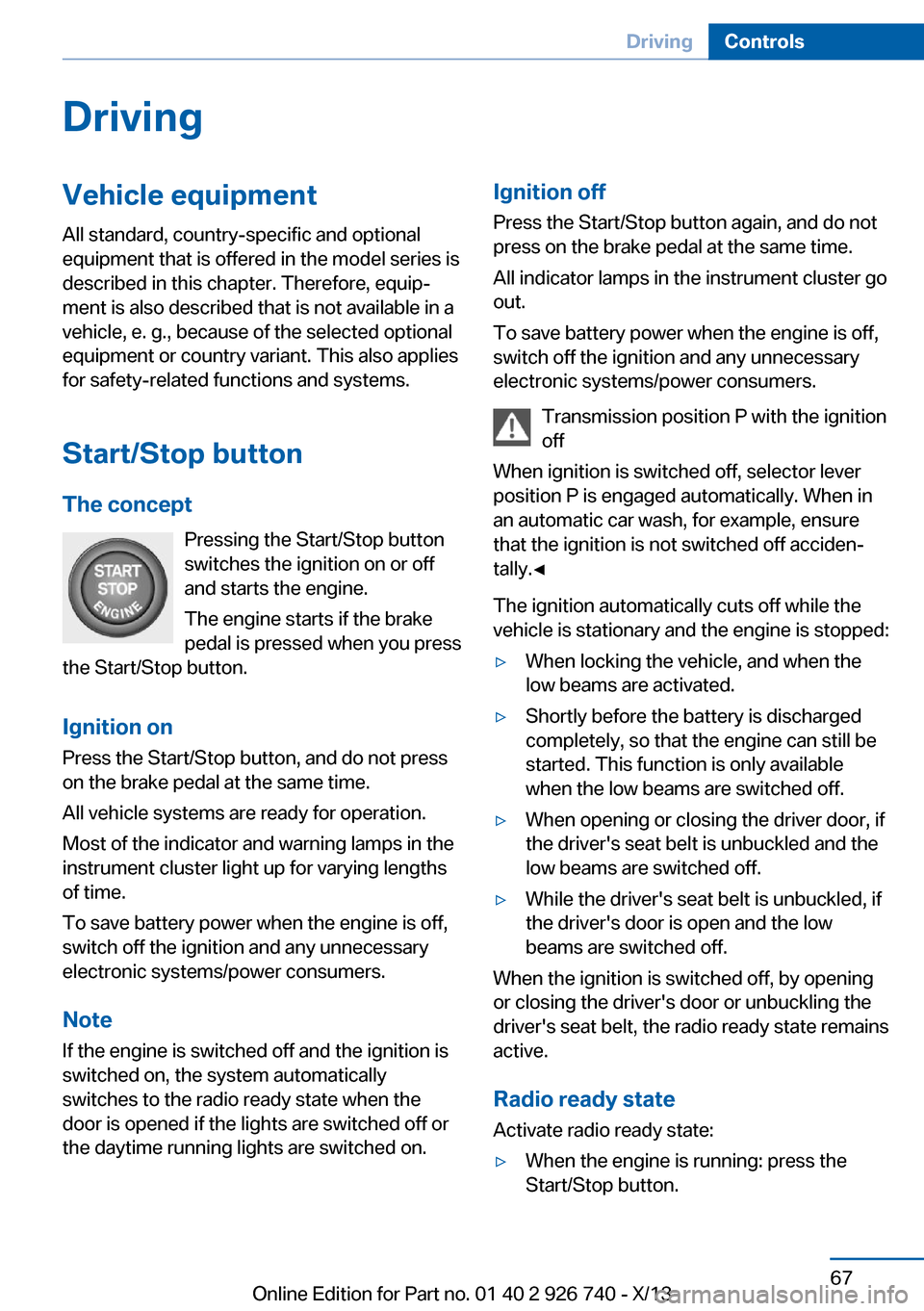
Start/Stop button The concept Pressing the Start/Stop button
switches the ignition on or off
and starts the engine.
The engine starts if the brake
pedal is pressed when you press
the Start/Stop button.
Ignition onPress the Start/Stop button, and do not press
on the brake pedal at the same time.
All vehicle systems are ready for operation.
Most of the indicator and warning lamps in the
instrument cluster light up for varying lengths
of time.
To save battery power when the engine is off,
switch off the ignition and any unnecessary
electronic systems/power consumers.
Note If the engine is switched off and the ignition is
switched on, the system automatically
switches to the radio ready state when the
door is opened if the lights are switched off or
the daytime running lights are switched on.Ignition off
Press the Start/Stop button again, and do not
press on the brake pedal at the same time.
All indicator lamps in the instrument cluster go
out.
To save battery power when the engine is off,
switch off the ignition and any unnecessary
electronic systems/power consumers.
Transmission position P with the ignition
off
When ignition is switched off, selector lever
position P is engaged automatically. When in
an automatic car wash, for example, ensure
that the ignition is not switched off acciden‐
tally.◀
The ignition automatically cuts off while the
vehicle is stationary and the engine is stopped:▷When locking the vehicle, and when the
low beams are activated.▷Shortly before the battery is discharged
completely, so that the engine can still be
started. This function is only available
when the low beams are switched off.▷When opening or closing the driver door, if
the driver's seat belt is unbuckled and the
low beams are switched off.▷While the driver's seat belt is unbuckled, if
the driver's door is open and the low
beams are switched off.
When the ignition is switched off, by opening
or closing the driver's door or unbuckling the
driver's seat belt, the radio ready state remains
active.
Radio ready state
Activate radio ready state:
▷When the engine is running: press the
Start/Stop button.Seite 67DrivingControls67
Online Edition for Part no. 01 40 2 926 740 - X/13
Page 70 of 265
Starting the engineThe engine starts automatically under the fol‐
lowing conditions:▷Automatic transmission:
By releasing the brake pedal.
When Automatic Hold is activated: press
the accelerator.
After the engine starts, accelerate as usual.
Safety mode
After the engine switches off automatically, it
will not start again automatically if any one of
the following conditions are met.
▷The driver's safety belt is unbuckled and
the driver's door is open.▷The hood was unlocked.
Some indicator lamps light up for varying
lengths of time.
The engine can only be started via the Start/
Stop button.
Note Even if driving away was not intended, the de‐
activated engine starts up automatically in the
following situations:
▷Excessive warming of the passenger com‐
partment when the cooling function is
switched on.▷The steering wheel is turned.▷Automatic transmission: the transmission
position is changed from D to N, R, or M/S.▷Automatic transmission: the transmission
position is changed from P to N, D, R or
M/S.▷Fogging of the windows when the auto‐
matic climate control is switched on.▷Vehicle battery is heavily discharged.▷Excessive cooling of the passenger com‐
partment when the heating is switched on.Preventing an automatic engine stop with automatic transmission
The concept To make it possible to drive away very quickly,
such as at an intersection, the automatic en‐
gine stop can be actively prevented.
Preventing an engine stop using the
brake pedal
The engine stop can be actively prevented
within one second after the vehicle comes to a
standstill.▷Immediately after the vehicle comes to a
standstill, briefly press the brake pedal
forcefully.▷Then press the brake pedal with normal
braking force.
Activating/deactivating the system
manually
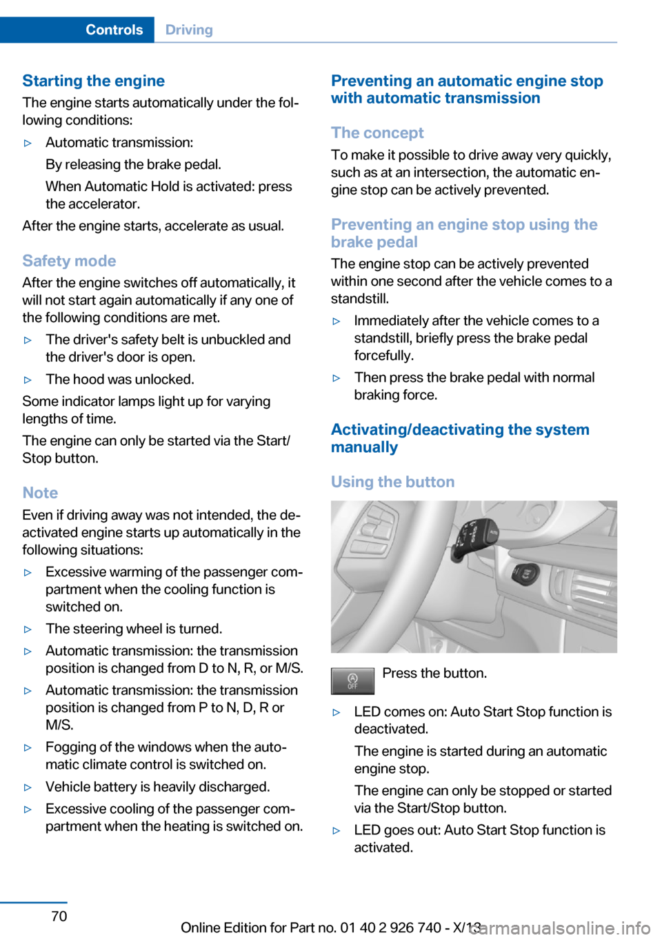
Using the button
Press the button.
▷LED comes on: Auto Start Stop function is
deactivated.
The engine is started during an automatic
engine stop.
The engine can only be stopped or started
via the Start/Stop button.▷LED goes out: Auto Start Stop function is
activated.Seite 70ControlsDriving70
Online Edition for Part no. 01 40 2 926 740 - X/13
Page 79 of 265
Engaging D, R and N
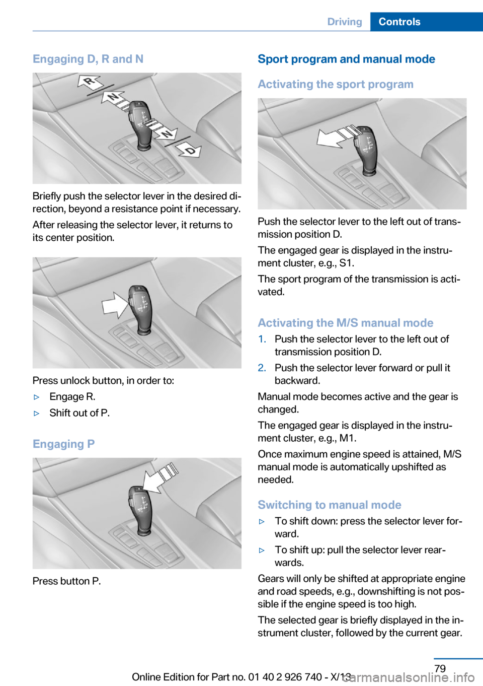
Briefly push the selector lever in the desired di‐
rection, beyond a resistance point if necessary.
After releasing the selector lever, it returns to
its center position.
Press unlock button, in order to:
▷Engage R.▷Shift out of P.
Engaging P
Press button P.
Sport program and manual mode
Activating the sport program
Push the selector lever to the left out of trans‐
mission position D.
The engaged gear is displayed in the instru‐
ment cluster, e.g., S1.
The sport program of the transmission is acti‐
vated.
Activating the M/S manual mode
1.Push the selector lever to the left out of
transmission position D.2.Push the selector lever forward or pull it
backward.
Manual mode becomes active and the gear is
changed.
The engaged gear is displayed in the instru‐
ment cluster, e.g., M1.
Once maximum engine speed is attained, M/S
manual mode is automatically upshifted as
needed.
Switching to manual mode
▷To shift down: press the selector lever for‐
ward.▷To shift up: pull the selector lever rear‐
wards.
Gears will only be shifted at appropriate engine
and road speeds, e.g., downshifting is not pos‐
sible if the engine speed is too high.
The selected gear is briefly displayed in the in‐
strument cluster, followed by the current gear.
Seite 79DrivingControls79
Online Edition for Part no. 01 40 2 926 740 - X/13
Page 87 of 265
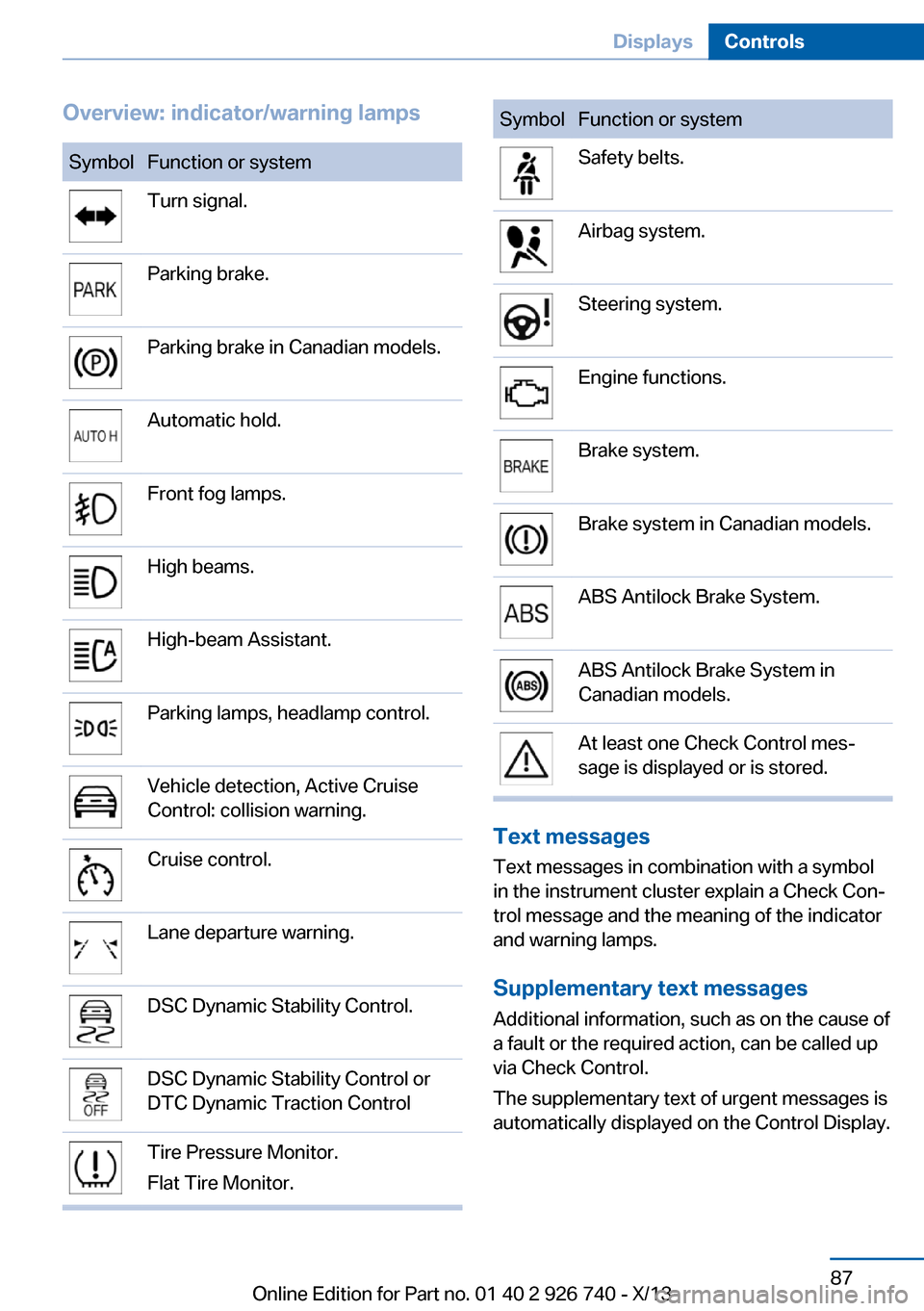
Overview: indicator/warning lampsSymbolFunction or systemTurn signal.Parking brake.Parking brake in Canadian models.Automatic hold.Front fog lamps.High beams.High-beam Assistant.Parking lamps, headlamp control.Vehicle detection, Active Cruise
Control: collision warning.Cruise control.Lane departure warning.DSC Dynamic Stability Control.DSC Dynamic Stability Control or
DTC Dynamic Traction ControlTire Pressure Monitor.
Flat Tire Monitor.SymbolFunction or systemSafety belts.Airbag system.Steering system.Engine functions.Brake system.Brake system in Canadian models.ABS Antilock Brake System.ABS Antilock Brake System in
Canadian models.At least one Check Control mes‐
sage is displayed or is stored.
Text messages
Text messages in combination with a symbol
in the instrument cluster explain a Check Con‐ trol message and the meaning of the indicator
and warning lamps.
Supplementary text messages
Additional information, such as on the cause of
a fault or the required action, can be called up
via Check Control.
The supplementary text of urgent messages is
automatically displayed on the Control Display.
Seite 87DisplaysControls87
Online Edition for Part no. 01 40 2 926 740 - X/13
Page 91 of 265
Automatic Service Request
Data regarding the service status or legally
mandated inspections of the vehicle are auto‐
matically transmitted to your service center
before a service due date.
You can check when your service center was
notified.1."Vehicle Info"2."Vehicle status"3.Open "Options".4."Last Service Request"
Gear shift indicator
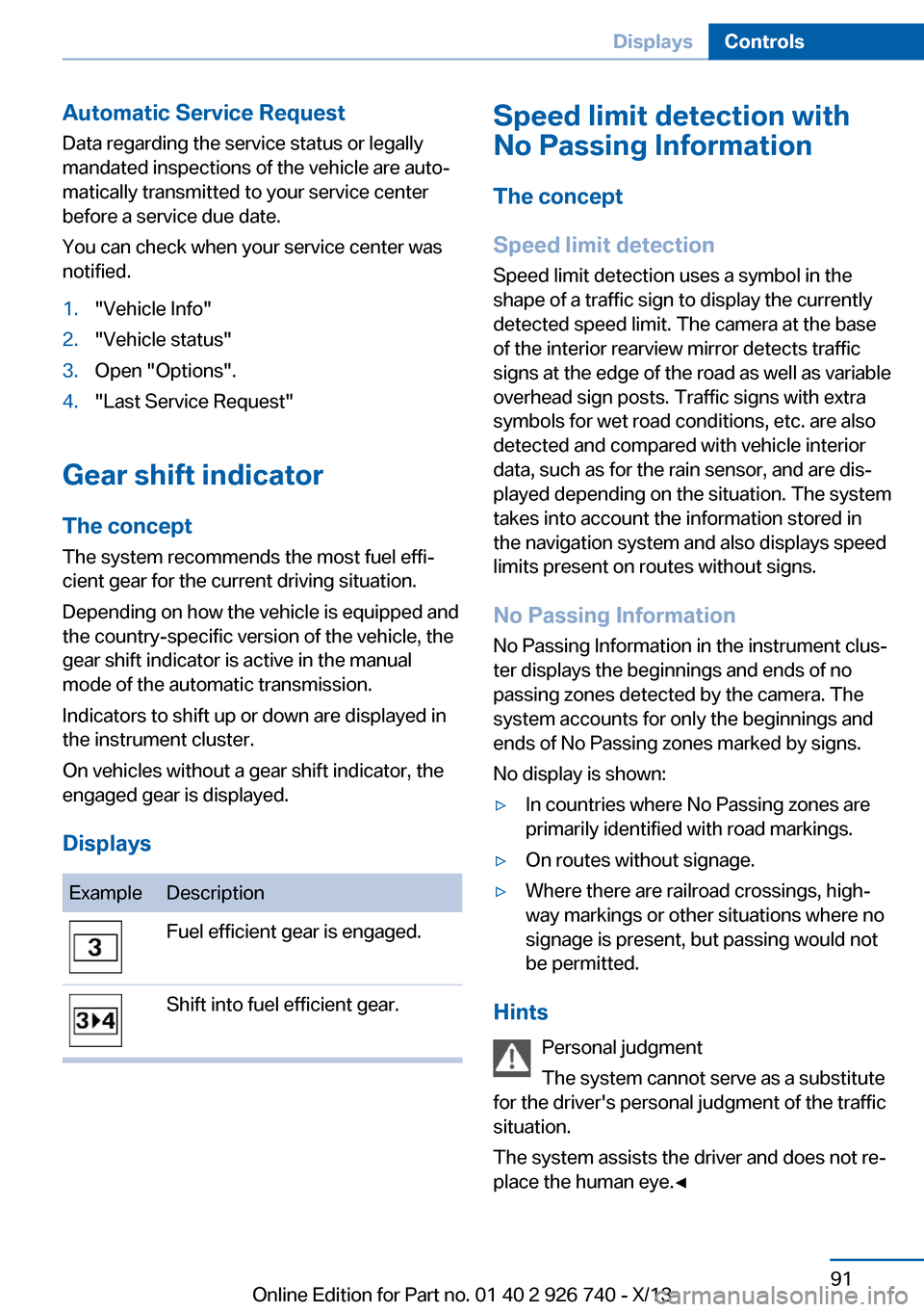
The conceptThe system recommends the most fuel effi‐
cient gear for the current driving situation.
Depending on how the vehicle is equipped and
the country-specific version of the vehicle, the
gear shift indicator is active in the manual
mode of the automatic transmission.
Indicators to shift up or down are displayed in
the instrument cluster.
On vehicles without a gear shift indicator, the
engaged gear is displayed.
Displays
ExampleDescriptionFuel efficient gear is engaged.Shift into fuel efficient gear.Speed limit detection with
No Passing Information
The concept
Speed limit detection Speed limit detection uses a symbol in the
shape of a traffic sign to display the currently
detected speed limit. The camera at the base
of the interior rearview mirror detects traffic
signs at the edge of the road as well as variable
overhead sign posts. Traffic signs with extra
symbols for wet road conditions, etc. are also
detected and compared with vehicle interior
data, such as for the rain sensor, and are dis‐
played depending on the situation. The system
takes into account the information stored in
the navigation system and also displays speed
limits present on routes without signs.
No Passing Information No Passing Information in the instrument clus‐
ter displays the beginnings and ends of no
passing zones detected by the camera. The
system accounts for only the beginnings and
ends of No Passing zones marked by signs.
No display is shown:▷In countries where No Passing zones are
primarily identified with road markings.▷On routes without signage.▷Where there are railroad crossings, high‐
way markings or other situations where no
signage is present, but passing would not
be permitted.
Hints
Personal judgment
The system cannot serve as a substitute
for the driver's personal judgment of the traffic
situation.
The system assists the driver and does not re‐
place the human eye.◀
Seite 91DisplaysControls91
Online Edition for Part no. 01 40 2 926 740 - X/13
Page 94 of 265
When destination guidance is activated in
the navigation system.
When the arrow view in the Head-up Dis‐
play is inactive.▷Compass display in the navigation system.
Adjusting the info display
You can select what information from the on‐
board computer is to be displayed on the info
display of the instrument cluster.
1."Settings"2."Info display"3.Select the desired displays.
Information in detail
Range
Displays the estimated cruising range available
with the remaining fuel.
It is calculated based on your driving style over
the last 20 miles/30 km.
Average fuel consumption
The average fuel consumption is calculated for
the period during which the engine is running.
The average fuel consumption is calculated for
the distance traveled since the last reset by the
onboard computer.
Average speed
Periods in which the vehicle is parked with the
engine manually stopped do not enter into the
calculation of the average speed.
Resetting average values
Press and hold the computer button on the turn signal lever.
Distance to destination
The distance remaining to the destination is
displayed if a destination is entered in the navi‐
gation system before the trip is started.
The distance to the destination is adopted au‐
tomatically.
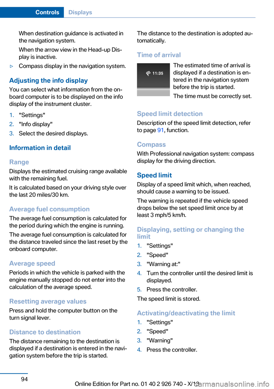
Time of arrival The estimated time of arrival is
displayed if a destination is en‐
tered in the navigation system
before the trip is started.
The time must be correctly set.
Speed limit detection
Description of the speed limit detection, refer
to page 91, function.
Compass With Professional navigation system: compass
display for the driving direction.
Speed limit
Display of a speed limit which, when reached,
should cause a warning to be issued.
The warning is repeated if the vehicle speed
drops below the set speed limit once by at
least 3 mph/5 km/h.
Displaying, setting or changing the
limit1."Settings"2."Speed"3."Warning at:"4.Turn the controller until the desired limit is
displayed.5.Press the controller.
The speed limit is stored.
Activating/deactivating the limit
1."Settings"2."Speed"3."Warning"4.Press the controller.Seite 94ControlsDisplays94
Online Edition for Part no. 01 40 2 926 740 - X/13
Page 101 of 265
To avoid blinding oncoming traffic, the Adap‐
tive Light Control does not swivel to the driv‐
er's side when the vehicle is at a standstill.
When driving in reverse, only the cornering
lamp is active.
Self-leveling headlamps The self-leveling headlamps compensate for
acceleration and braking operations in order
not to blind the oncoming traffic and to achieve
optimum illumination of the roadway.
Malfunction
A Check Control message is displayed.
Adaptive light control is malfunctioning or has
failed. Have the system checked as soon as
possible.
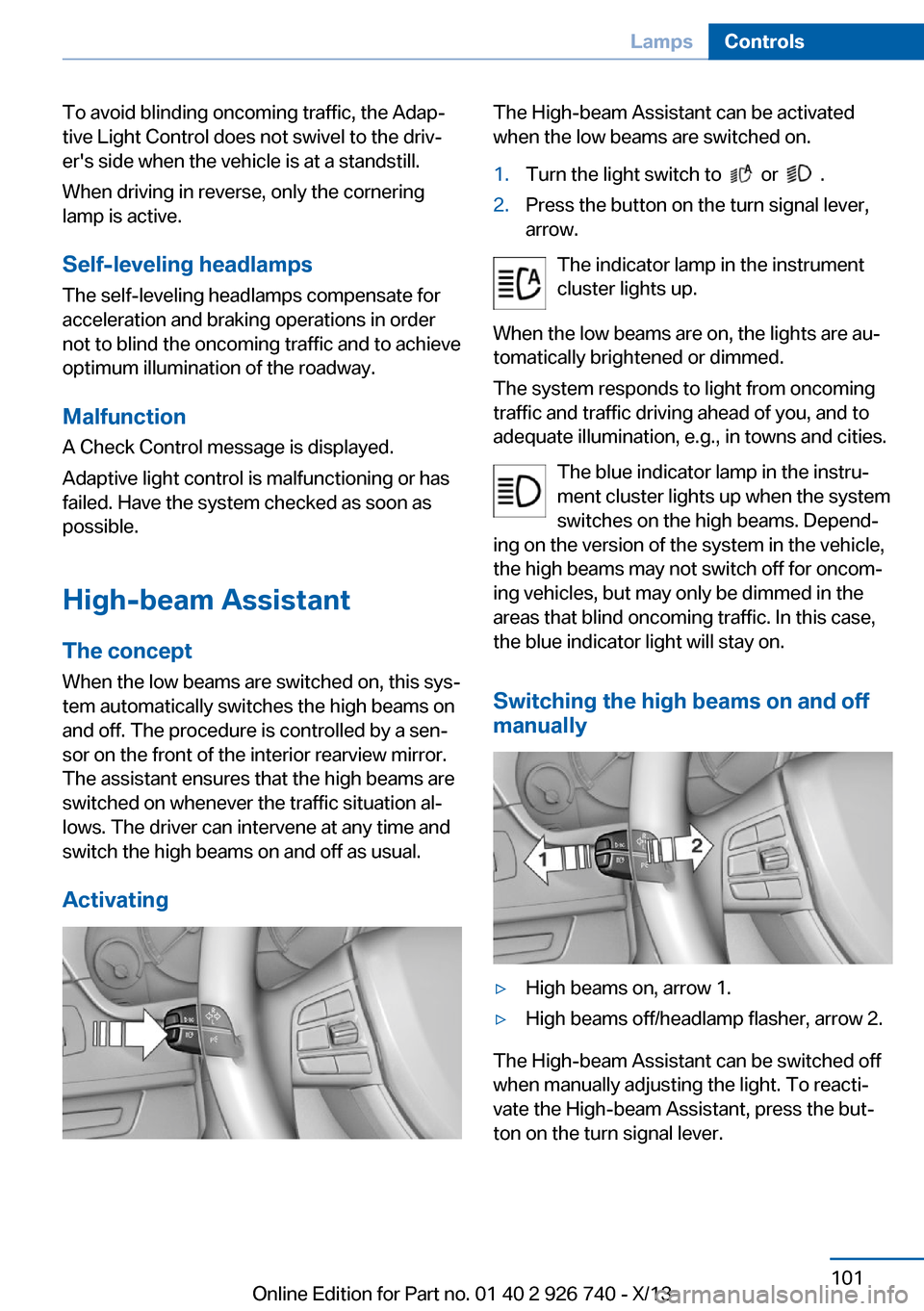
High-beam Assistant The conceptWhen the low beams are switched on, this sys‐
tem automatically switches the high beams on
and off. The procedure is controlled by a sen‐
sor on the front of the interior rearview mirror.
The assistant ensures that the high beams are
switched on whenever the traffic situation al‐
lows. The driver can intervene at any time and
switch the high beams on and off as usual.
ActivatingThe High-beam Assistant can be activated
when the low beams are switched on.1.Turn the light switch to or .2.Press the button on the turn signal lever,
arrow.
The indicator lamp in the instrument
cluster lights up.
When the low beams are on, the lights are au‐
tomatically brightened or dimmed.
The system responds to light from oncoming
traffic and traffic driving ahead of you, and to
adequate illumination, e.g., in towns and cities.
The blue indicator lamp in the instru‐
ment cluster lights up when the system
switches on the high beams. Depend‐
ing on the version of the system in the vehicle, the high beams may not switch off for oncom‐
ing vehicles, but may only be dimmed in the
areas that blind oncoming traffic. In this case,
the blue indicator light will stay on.
Switching the high beams on and off
manually
▷High beams on, arrow 1.▷High beams off/headlamp flasher, arrow 2.
The High-beam Assistant can be switched off
when manually adjusting the light. To reacti‐
vate the High-beam Assistant, press the but‐
ton on the turn signal lever.
Seite 101LampsControls101
Online Edition for Part no. 01 40 2 926 740 - X/13
Page 107 of 265
Detected child seatsThe system generally detects children seated
in a child seat, especially in the child seats that
were required by NHTSA when the vehicle was
manufactured. After installing a child seat,
make sure that the indicator lamp for the front
passenger airbags lights up. This indicates that the child seat has been detected and the
front passenger airbags are not activated.
Strength of the driver's and front
passenger airbag
The strength with which the driver's and front
passenger airbags are triggered depends on
the position of the driver's and front passenger
seats.
To maintain the accuracy of this function over
the long-term, calibrate the front seats when a
corresponding message appears on the Con‐
trol Display.
Calibrating the front seats A corresponding message appears on the
Control Display.1.Move the respective seat forward all the
way.2.Move the respective seat forward again. It
moves forward briefly.3.Readjust the seat to the desired position.
The calibration procedure is completed when
the message on the Control Display disap‐
pears.
If the message continues to be displayed, re‐
peat the calibration.
If the message does not disappear after a re‐
peat calibration, have the system checked as
soon as possible.
Unobstructed area of movement
Ensure that the area of movement of the
seats is unobstructed to avoid personal injury
or damage to objects.◀
Tire Pressure Monitor TPM
The concept The system monitors tire pressure in the four
mounted tires. The system warns you if there
is a significant loss of pressure in one or more
tires. For this purpose, sensors in the tire
valves measure the tire inflation pressure.
Hints Tire damage due to external factors
Sudden tire damage caused by external
influences cannot be indicated in advance.◀
Pay attention to the other information and indi‐
cations under Tire inflation pressure, refer to
page 211, as well when using the system.
Functional requirements
The system must have been reset with the
correct tire inflation pressure; otherwise, relia‐
ble signaling of tire pressure loss is not en‐
sured.
Reset the system again after each correction
of the tire inflation pressure and after every tire
or wheel change.
Always use wheels with TPM electronics to
ensure that the system will operate properly.
Status display The current status of the Tire Pressure Moni‐
tor TPM can be displayed on the Control Dis‐
play, e.g., whether or not the TPM is active.1."Vehicle Info"2."Vehicle status"3. "Tire Pressure Monitor (TPM)"
The status is displayed.
Status display The tire and system status is indicated by the
color of the wheels and a text message on the
Control Display.
Seite 107SafetyControls107
Online Edition for Part no. 01 40 2 926 740 - X/13
Page 108 of 265
All wheels green
System is active and will issue a warning rela‐
tive to the tire inflation pressures stored during
the last reset.
One wheel is yellow
A flat tire or major drop in inflation pressure in
the indicated tire.
All wheels are yellow A flat tire or major drop in inflation pressure in
several tires.
Wheels, gray
The system cannot detect a flat tire. Reasons
for this may be:▷The system is being reset.▷Malfunction.
Additional information
The status display additionally shows the cur‐
rent tire inflation pressures. The values shown
are current measurement values and may vary
depending on driving style or weather condi‐
tions.
Carry out reset
Reset the system after each correction of the
tire inflation pressure and after every tire or
wheel change.
1."Vehicle Info"2."Vehicle status"3. "Perform reset"4.Start the engine - do not drive away.5.Carry out the reset with "Perform reset".6.Drive away.
The tires are shown in gray and the status is
displayed.
After driving faster than 19 mph/30 km/h for a
short period, the tire inflation pressures set are
accepted as reference values. The reset is
completed automatically during driving.
The progress of the reset is displayed.
After a successfully completed Reset, the
wheels on the Control Display are shown in
green and "Tire Pressure Monitor (TPM)
active" is displayed.
The trip can be interrupted at any time. If you
drive away again, the reset resumes automati‐
cally.
Low tire pressure message The yellow warning lamp lights up. A
Check Control message is displayed.▷There is a flat tire or a major loss in
tire inflation pressure.▷No reset was performed for the system.
The system therefore issues a warning
based on the tire inflation pressures before
the last reset.1.Reduce your speed and stop cautiously.
Avoid sudden braking and steering maneu‐
vers.2.Check whether the vehicle is fitted with
regular tires or run-flat tires.
Run-flat tires, refer to page 220, are la‐
beled with a circular symbol containing the
letters RSC marked on the tire sidewall.
Do not continue driving without run-flat
tires
Do not continue driving if the vehicle is not
equipped with run-flat tires; continued driving
may result in serious accidents.◀
When a low inflation pressure is indicated,
DSC Dynamic Stability Control is switched on
if necessary.
Actions in the event of a flat tire
Normal tires
1.Identify the damaged tire.
Do this by checking the air pressure in all
four tires.Seite 108ControlsSafety108
Online Edition for Part no. 01 40 2 926 740 - X/13