active BMW X5 2014 F15 Workshop Manual
[x] Cancel search | Manufacturer: BMW, Model Year: 2014, Model line: X5, Model: BMW X5 2014 F15Pages: 265, PDF Size: 6.2 MB
Page 149 of 265
The arrangement of the buttons varies accord‐
ing to the how the vehicle is equipped or coun‐
try-specific variants.
Switching on Press the button on the steering
wheel.
The marking in the speedometer is set to the
current speed.
The cruise control can be used.
Switching off Deactivated or interrupted system
If the system is deactivated or inter‐
rupted, actively intervene by braking and, if
necessary, with evasive maneuvers; otherwise,
there is the danger of an accident occurring.◀
Press the button on the steering
wheel.▷If active: press twice.▷If interrupted: press once.
The displays go out. The stored desired speed
is deleted.
Interrupting When active, press the button.
The system is automatically interrupted if:
▷The brakes are applied.▷The transmission position D is disengaged.▷DTC Dynamic Traction Control is activated
or DSC is deactivated.▷DSC is actively controlling stability.▷HDC is activated.▷When SPORT+ is activated with Driving
Dynamics Control.
Maintaining/storing the current speed
Press the button.
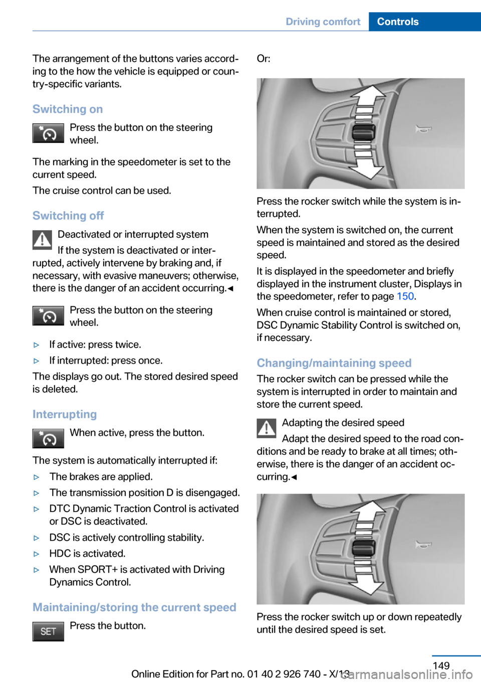
Or:
Press the rocker switch while the system is in‐
terrupted.
When the system is switched on, the current
speed is maintained and stored as the desired
speed.
It is displayed in the speedometer and briefly
displayed in the instrument cluster, Displays in
the speedometer, refer to page 150.
When cruise control is maintained or stored,
DSC Dynamic Stability Control is switched on,
if necessary.
Changing/maintaining speed The rocker switch can be pressed while the
system is interrupted in order to maintain and
store the current speed.
Adapting the desired speed
Adapt the desired speed to the road con‐
ditions and be ready to brake at all times; oth‐
erwise, there is the danger of an accident oc‐
curring.◀
Press the rocker switch up or down repeatedly
until the desired speed is set.
Seite 149Driving comfortControls149
Online Edition for Part no. 01 40 2 926 740 - X/13
Page 150 of 265
If active, the displayed speed is stored and the
vehicle reaches the stored speed if the road is
clear.▷Each time the rocker switch is pressed to
the point of resistance, the desired speed
increases or decreases by approx.
1 mph/1 km/h.▷Each time the rocker switch is pressed
past the point of resistance, the desired
speed increases or decreases by a maxi‐
mum of 5 mph/10 km/h.
The maximum speed that can be set de‐
pends on the vehicle.▷Pressing the rocker switch to the resist‐
ance point and holding it accelerates or de‐
celerates the vehicle without requiring
pressure on the accelerator pedal. After
the rocker switch is released, the vehicle
maintains its final speed. Pressing the
switch beyond the resistance point causes
the vehicle to accelerate more rapidly.
Resuming the desired speed
Press the button.
The stored speed is reached and maintained. Displays in the instrument cluster
Indicator lamp Depending on how the vehicle is equip‐
ped, the indicator lamp in the instru‐
ment cluster indicates whether the sys‐
tem is switched on.
Desired speed
▷The marking lights up green:
the system is active.▷The marking lights up or‐
ange: the system has been
interrupted.▷The marking does not light up: the system
is switched off.
Brief status display
Selected desired speed.
If --- appears briefly on the display for Check
Control messages, it is possible that the sys‐
tem requirements for operation are currently
not met.
PDC Park Distance Control
The concept PDC supports you when parking. Objects that
you are approaching slowly in front of or be‐
hind your vehicle are indicated by:
▷Signal tones.▷Visual display.
General information
Measurements are made by ultrasound sen‐
sors in the bumpers.
The range, depending on the environment, is
approx. 6 ft/2 m.
An acoustic warning is first given:
▷By the front sensors and the two rear cor‐
ner sensors at approx. 24 in/60 cm.▷By the rear middle sensors at approx.
5 ft/1.50 m.
To ensure full operability:
▷Do not cover sensors, e.g., by stickers, bi‐
cycle racks and the like.▷Keep the sensors clean and free of ice.▷When using high-pressure washers, do not
spray the sensors for long periods and
maintain a distance of at least 12 in/30 cm.Seite 150ControlsDriving comfort150
Online Edition for Part no. 01 40 2 926 740 - X/13
Page 151 of 265
HintsPersonal responsibility
Even an active system does not relieve
the driver from personal responsibility for the
driving process.
Because of technical system limits, the system
cannot independently react appropriately in all
traffic situations.
Continuously and attentively monitor the driv‐
ing process, the area surrounding the vehicle
and the traffic situation, and actively intervene
when required, otherwise, there is a risk of an
accident.◀
Avoid driving quickly with PDC
Avoid approaching an object quickly.
Avoid driving away quickly while PDC is not yet
active.
For technical reasons, the system may other‐
wise be too late in issuing a warning.◀
At a glance
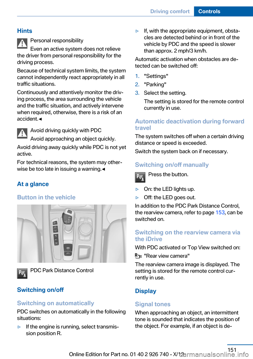
Button in the vehicle
PDC Park Distance Control
Switching on/off
Switching on automatically PDC switches on automatically in the following
situations:
▷If the engine is running, select transmis‐
sion position R.▷If, with the appropriate equipment, obsta‐
cles are detected behind or in front of the
vehicle by PDC and the speed is slower
than approx. 2 mph/3 km/h.
Automatic activation when obstacles are de‐
tected can be switched off:
1."Settings"2."Parking"3.Select the setting.
The setting is stored for the remote control
currently in use.
Automatic deactivation during forward
travel
The system switches off when a certain driving
distance or speed is exceeded.
Switch the system back on if necessary.
Switching on/off manually Press the button.
▷On: the LED lights up.▷Off: the LED goes out.
In addition to the PDC Park Distance Control,
the rearview camera, refer to page 153, can be
switched on.
Switching on the rearview camera viathe iDrive
With PDC activated or Top View switched on:
"Rear view camera"
The rearview camera image is displayed. The
setting is stored for the remote control cur‐
rently in use.
Display
Signal tones When approaching an object, an intermittent
tone is sounded that indicates the position of
the object. For example, if an object is de‐
Seite 151Driving comfortControls151
Online Edition for Part no. 01 40 2 926 740 - X/13
Page 158 of 265
Panorama Side View
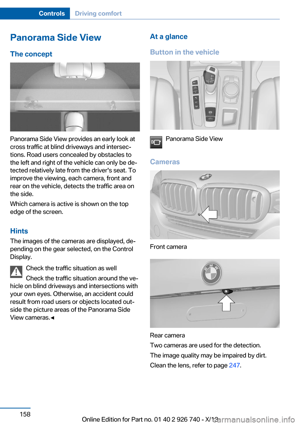
The concept
Panorama Side View provides an early look at
cross traffic at blind driveways and intersec‐
tions. Road users concealed by obstacles to
the left and right of the vehicle can only be de‐
tected relatively late from the driver's seat. To
improve the viewing, each camera, front and
rear on the vehicle, detects the traffic area on
the side.
Which camera is active is shown on the top
edge of the screen.
Hints The images of the cameras are displayed, de‐
pending on the gear selected, on the Control
Display.
Check the traffic situation as well
Check the traffic situation around the ve‐
hicle on blind driveways and intersections with
your own eyes. Otherwise, an accident could
result from road users or objects located out‐
side the picture areas of the Panorama Side
View cameras.◀
At a glance
Button in the vehicle
Panorama Side View
Cameras
Front camera
Rear camera
Two cameras are used for the detection.
The image quality may be impaired by dirt.
Clean the lens, refer to page 247.
Seite 158ControlsDriving comfort158
Online Edition for Part no. 01 40 2 926 740 - X/13
Page 160 of 265
Ultrasound sensors measure parking spaces
on both sides of the vehicle.
The parking assistant calculates the best pos‐
sible parking line and during the parking proce‐
dure takes control of steering, the acceleration
and braking and if necessary changes the drive
modes. Hold down the parking assistant but‐
ton for the duration of the parking operation. At
the end of the parking procedure, the P selec‐
tor lever position is engaged.
When parking, also take note of the visual and
acoustic information and instructions issued
by the PDC, the parking assistant and the rear‐
view camera and react accordingly.
A component of the parking assistant is the
PDC Park Distance Control, refer to page 150.
Hints Personal responsibility
Even an active system does not relieve
the driver from personal responsibility for the
driving process.
Because of technical system limits, the system
cannot independently react appropriately in all
traffic situations.
Continuously and attentively monitor the driv‐
ing process, the area surrounding the vehicle
and the traffic situation, and actively intervene
when required, otherwise, there is a risk of an
accident.◀
Changes to the parking space
Changes to the parking space after it was
measured are not taken into account by the
system.
Therefore, always be alert and ready to inter‐
vene; otherwise, there is the danger of an acci‐
dent occurring.◀
Transporting loads
Loads that extend beyond the perimeter
of the vehicle are not taken into account by the
system during the parking procedure.Therefore, always be alert and ready to inter‐
vene; otherwise, there is the danger of an acci‐
dent occurring.◀
Curbs
The parking assistant may steer the vehi‐
cle over or onto curbs.
Therefore, always be alert and ready to inter‐
vene; otherwise, the wheels, tires, or the vehi‐
cle may become damaged.◀
An engine that has been switched off by the
Auto Start Stop function is restarted automati‐
cally when the parking assistant is activated.
Requirements
For measuring parking spaces▷Maximum speed while driving forward ap‐
prox. 22 mph/35 km/h.▷Maximum distance to row of parked vehi‐
cles: 5 ft/1.5 m.
Suitable parking space
▷Gap between two objects with a minimum
length of approx. 5 ft/1.5 m.▷Minimum length of the gap: own vehicle's
length plus approx. 4 ft/1.2 m.▷Minimum depth: approx. 5 ft/1.5 m.
For parking procedure
▷Doors and tailgate closed.▷Parking brake released.Seite 160ControlsDriving comfort160
Online Edition for Part no. 01 40 2 926 740 - X/13
Page 162 of 265
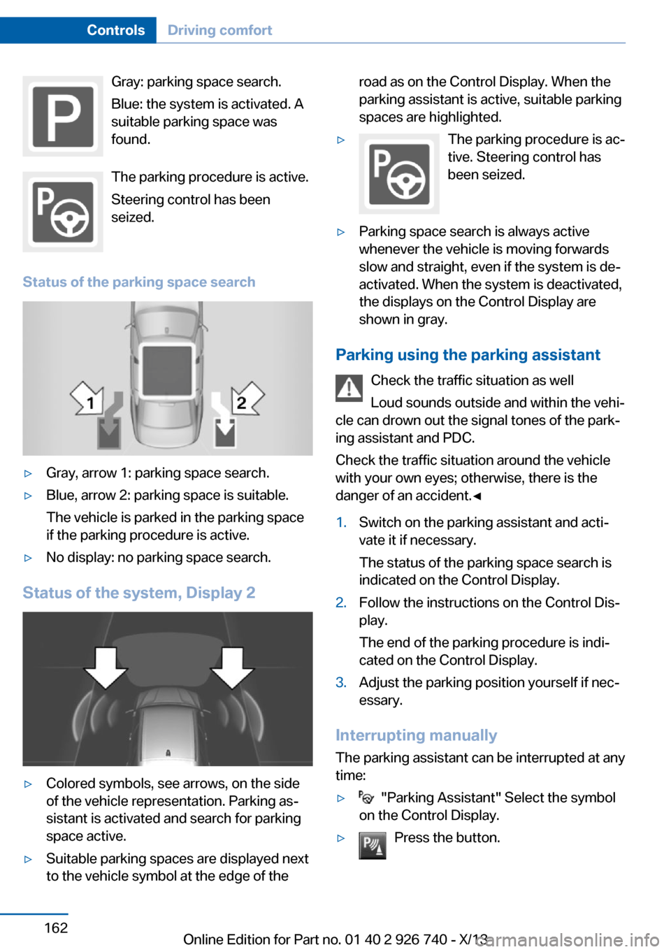
Gray: parking space search.
Blue: the system is activated. A
suitable parking space was
found.
The parking procedure is active.
Steering control has been
seized.
Status of the parking space search▷Gray, arrow 1: parking space search.▷Blue, arrow 2: parking space is suitable.
The vehicle is parked in the parking space
if the parking procedure is active.▷No display: no parking space search.
Status of the system, Display 2
▷Colored symbols, see arrows, on the side
of the vehicle representation. Parking as‐
sistant is activated and search for parking
space active.▷Suitable parking spaces are displayed next
to the vehicle symbol at the edge of theroad as on the Control Display. When the
parking assistant is active, suitable parking
spaces are highlighted.▷The parking procedure is ac‐
tive. Steering control has
been seized.▷Parking space search is always active
whenever the vehicle is moving forwards
slow and straight, even if the system is de‐
activated. When the system is deactivated,
the displays on the Control Display are
shown in gray.
Parking using the parking assistant
Check the traffic situation as well
Loud sounds outside and within the vehi‐
cle can drown out the signal tones of the park‐
ing assistant and PDC.
Check the traffic situation around the vehicle
with your own eyes; otherwise, there is the
danger of an accident.◀
1.Switch on the parking assistant and acti‐
vate it if necessary.
The status of the parking space search is
indicated on the Control Display.2.Follow the instructions on the Control Dis‐
play.
The end of the parking procedure is indi‐
cated on the Control Display.3.Adjust the parking position yourself if nec‐
essary.
Interrupting manually
The parking assistant can be interrupted at any
time:
▷ "Parking Assistant" Select the symbol
on the Control Display.▷Press the button.Seite 162ControlsDriving comfort162
Online Edition for Part no. 01 40 2 926 740 - X/13
Page 164 of 265
Malfunction
A Check Control message is displayed.
The parking assistant failed. Have the system
checked.
Distance information The conceptThe system displays a symbol in the Head-up
Display to indicate that the distance behind the
vehicle in front is not sufficient.
General information
The distance is determined by the radar sen‐
sor of the Active Cruise Control.
Hints Personal responsibility
The display does not relieve the driver of
the responsibility to adapt his or her distance
and driving style to the traffic conditions. Main‐
tain the prescribed safety distance.◀
At a glance
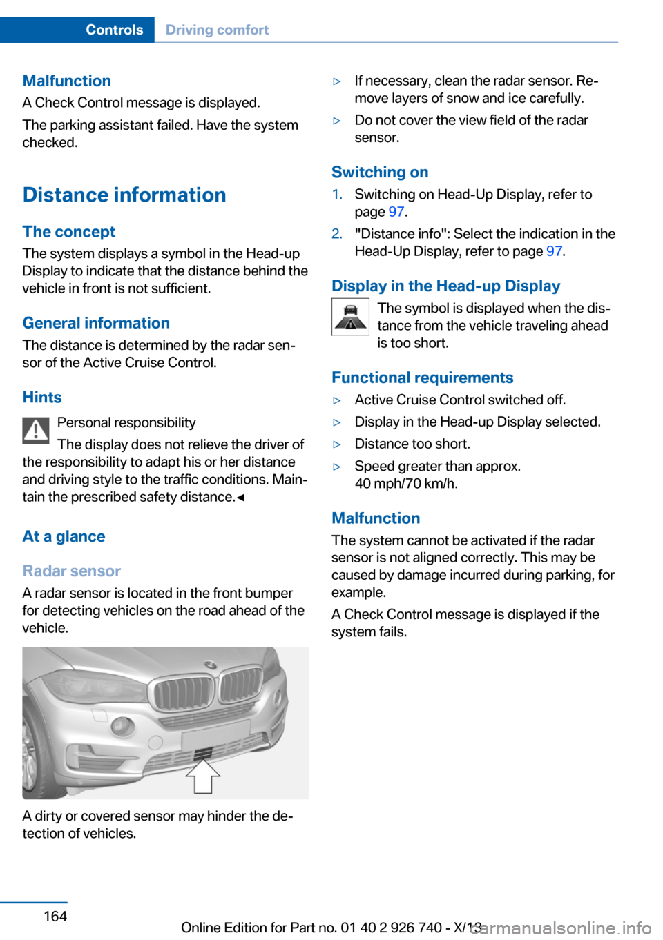
Radar sensor
A radar sensor is located in the front bumper
for detecting vehicles on the road ahead of the
vehicle.
A dirty or covered sensor may hinder the de‐
tection of vehicles.
▷If necessary, clean the radar sensor. Re‐
move layers of snow and ice carefully.▷Do not cover the view field of the radar
sensor.
Switching on
1.Switching on Head-Up Display, refer to
page 97.2."Distance info": Select the indication in the
Head-Up Display, refer to page 97.
Display in the Head-up Display
The symbol is displayed when the dis‐
tance from the vehicle traveling ahead
is too short.
Functional requirements
▷Active Cruise Control switched off.▷Display in the Head-up Display selected.▷Distance too short.▷Speed greater than approx.
40 mph/70 km/h.
Malfunction
The system cannot be activated if the radar
sensor is not aligned correctly. This may be
caused by damage incurred during parking, for
example.
A Check Control message is displayed if the
system fails.
Seite 164ControlsDriving comfort164
Online Edition for Part no. 01 40 2 926 740 - X/13
Page 165 of 265
Climate controlVehicle equipment
All standard, country-specific and optional
equipment that is offered in the model series is
described in this chapter. Therefore, equip‐ment is also described that is not available in a
vehicle, e. g., because of the selected optional
equipment or country variant. This also applies
for safety-related functions and systems.
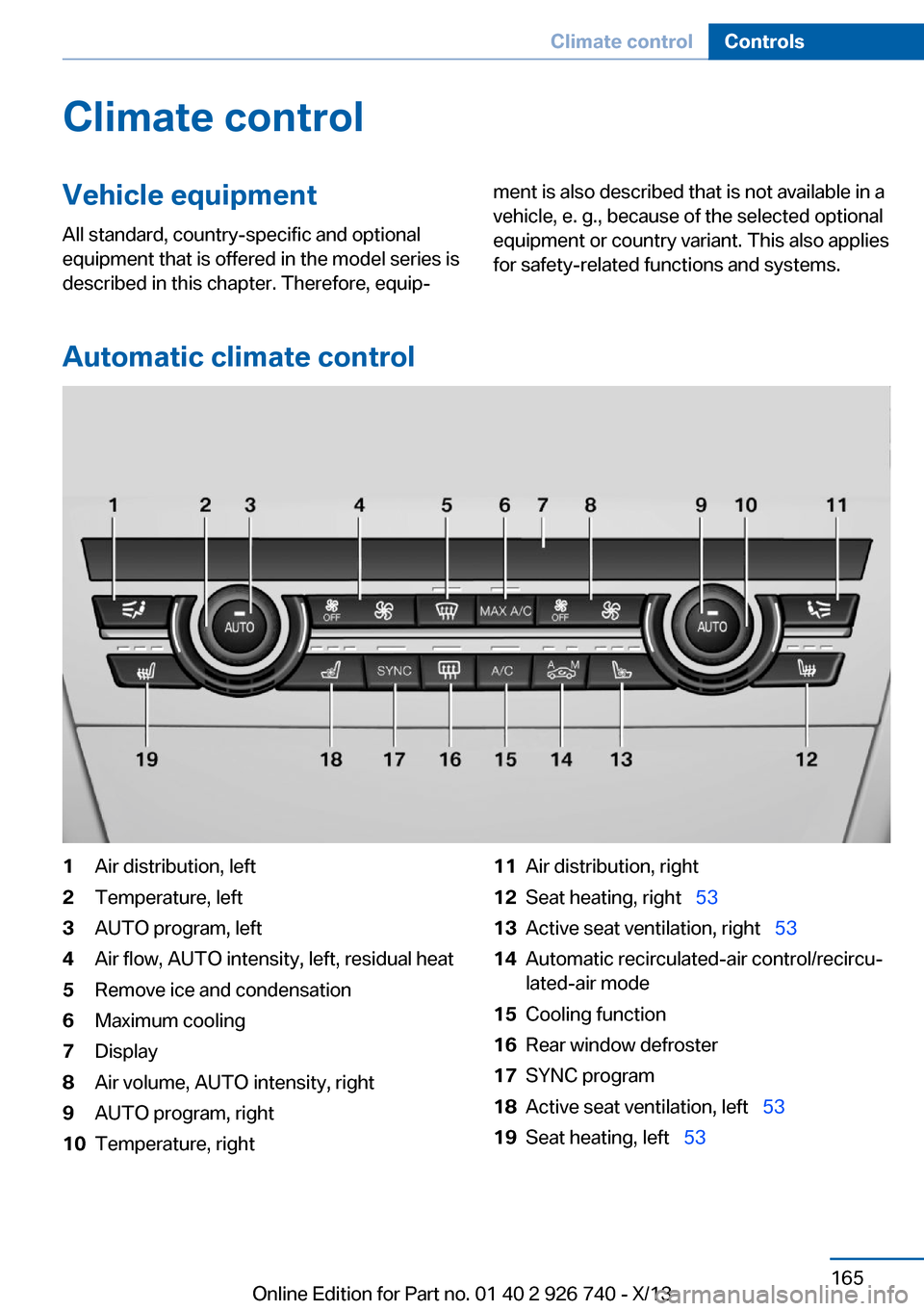
Automatic climate control
1Air distribution, left2Temperature, left3AUTO program, left4Air flow, AUTO intensity, left, residual heat5Remove ice and condensation6Maximum cooling7Display8Air volume, AUTO intensity, right9AUTO program, right10Temperature, right11Air distribution, right12Seat heating, right 5313Active seat ventilation, right 5314Automatic recirculated-air control/recircu‐
lated-air mode15Cooling function16Rear window defroster17SYNC program18Active seat ventilation, left 5319Seat heating, left 53Seite 165Climate controlControls165
Online Edition for Part no. 01 40 2 926 740 - X/13
Page 166 of 265
Climate control functions in detail
Manual air distribution Press the button repeatedly to select
a program:▷Upper body region.▷Upper body region and footwell.▷Footwell.▷Windows and footwell.▷Windows, upper body region, and footwell.▷Windows: driver's side only.▷Windows and upper body region.
If the windows are fogged over, press the
AUTO button on the driver's side to utilize the
condensation sensor.
Temperature Turn the wheel to set the de‐sired temperature.
The automatic climate control achieves this
temperature as quickly as possible, if neces‐
sary with the maximum cooling or heating ca‐
pacity, and then keeps it constant.
Avoid rapidly switching between different tem‐
perature settings. Otherwise, the automatic cli‐
mate control will not have sufficient time to ad‐
just the set temperature.
AUTO program Press the button.
Air flow, air distribution, and tempera‐
ture are controlled automatically.
Depending on the selected temperature,
AUTO intensity program and outside influen‐ ces, the air is directed to the windshield, side
windows, upper body, and into the footwell.
The cooling function, refer to page 167, is
switched on automatically with the AUTO pro‐
gram.
At the same time, a condensation sensor con‐
trols the program so as to prevent window
condensation as much as possible.
Intensity of the AUTO program
With the AUTO program switched on, auto‐
matic control of the air flow and air distribution
can be adjusted.
Press the left or right side of the but‐
ton: decrease or increase the inten‐
sity.
The selected intensity is shown on the display
of the automatic climate control.
Air flow, manual To be able to manually adjust the air flow,
switch off the AUTO program first.
Press the left or right side of the but‐
ton: decrease or increase air flow.
The selected air flow is shown on the display of
the automatic climate control.
The air flow of the automatic climate control
may be reduced automatically to save battery
power.
Defrosting windows and removing condensation
Press the button.
Ice and condensation are quickly re‐
moved from the windshield and the front side
windows.
The air volume can be adjusted when the pro‐
gram is active.
If the windows are fogged over, you can also
switch on the cooling function or press the
AUTO button to utilize the condensation sen‐
sor.Seite 166ControlsClimate control166
Online Edition for Part no. 01 40 2 926 740 - X/13
Page 167 of 265
Maximum coolingPress the button.
The system is set to the lowest tem‐
perature, maximum air flow and air circulation
mode.
Air flows out of the vents for the upper body
region. The vents need to be open for this.
The function is available above an external
temperature of approx. 32 ℉/0 ℃ and with the
engine running is indicated.
The air flow can be adjusted when the program
is active.
Automatic recirculated-air control/ recirculated-air mode
You can respond to unpleasant odors or pollu‐
tants in the immediate environment by tempo‐
rarily suspending the supply of outside air. The
system then recirculates the air currently
within the vehicle.
Press the button repeatedly to select
an operating mode:▷LEDs off: outside air flows in continuously.▷Left LED on, automatic recirculated-air
control: a sensor detects pollutants in the
outside air and controls the shutoff auto‐
matically.▷Right LED on, recirculated-air mode: the
supply of outside air into the vehicle is per‐
manently blocked.
If the windows are fogged over, switch off the
recirculated-air mode and press the AUTO
button on the driver's side to utilize the con‐
densation sensor. Make sure that air can flow
onto the windshield.
Continuous recirculated-air mode
The recirculated-air mode should not be
used for an extended period of time, as the air
quality inside the vehicle deteriorates stead‐
ily.◀
Cooling function
The passenger compartment can only be
cooled with the engine running.
Press the button.
The air is cooled and dehumidified
and, depending on the temperature setting,
warmed again.
Depending on the weather, the windshield may
fog up briefly when the engine is started.
The cooling function is switched on automati‐
cally with the AUTO program.
When using the automatic climate control,
condensation water, refer to page 192, devel‐
ops that exits underneath the vehicle.
Rear window defroster Press the button.
The rear window defroster switches
off automatically after a certain period of time.
SYNC program The current settings on the driver's
side for temperature, air flow, air distri‐
bution, and AUTO program are transferred to
the front passenger side and to the left and
right rear.
The program is switched off if the settings on
the front passenger side or in the rear are
changed.
Residual heat The heat stored in the engine is used to heat
the interior.
Functional requirement▷Up to 15 minutes after switching off the
engine.▷Warm engine.▷The battery is sufficiently charged.▷External temperature below 77 ℉/25 ℃.Seite 167Climate controlControls167
Online Edition for Part no. 01 40 2 926 740 - X/13