Service light BMW X5 2015 F15 User Guide
[x] Cancel search | Manufacturer: BMW, Model Year: 2015, Model line: X5, Model: BMW X5 2015 F15Pages: 275, PDF Size: 6.46 MB
Page 115 of 275
longer and the self-steering properties will
change. There is risk of an accident.
Drive moderately and do not exceed a speed of
50 mph/80 km/h.◀
Final tire failure
Vibrations or loud noises while driving can indi‐
cate the final failure of a tire.
Reduce speed and stop; otherwise, pieces of
the tire could come loose and cause an acci‐
dent.
Do not continue driving. Contact a dealer’s
service center or another qualified service cen‐
ter or repair shop.
Required tire inflation pressure check
message
A Check Control message is displayed in the
following situations▷The system has detected a wheel change,
but no reset was done.▷Inflation was not carried out according to
specifications.▷The tire inflation pressure has fallen below
the level of the last confirmation.
In this case:
▷Check the tire pressure and correct as
needed.▷Carry out a reset of the system after a tire
change.
System limits
The system does not function properly if a re‐
set has not been carried out, e.g., a flat tire is
reported though tire inflation pressures are
correct.
The tire inflation pressure depends on the
tire's temperature. Driving or exposure to the
sun will increase the tire's temperature, thus
increasing the tire inflation pressure. The tire
inflation pressure is reduced when the tire
temperature falls again. These circumstances
may cause a warning when temperatures fall
very sharply.
The system cannot indicate sudden serious
tire damage caused by external circumstances.
Malfunction The yellow warning lamp flashes and
then lights up continuously. A Check
Control message is displayed. No flat
tire or loss of tire inflation pressure can be de‐
tected.
Examples and recommendations in the follow‐
ing situations:▷A wheel without TPM electronics is
mounted: Have it checked by a dealer’s
service center or another qualified service
center or repair shop as needed.▷Malfunction: Have system checked by a
dealer’s service center or another qualified
service center or repair shop.▷TPM was unable to complete the reset.
Reset the system again.▷Interference through systems or devices
with the same radio frequency: After leav‐
ing the area of the interference, the system
automatically becomes active again.
Declaration according to NHTSA/
FMVSS 138 Tire Pressure Monitoring
System
Each tire, including the spare (if provided)
should be checked monthly when cold and in‐
flated to the inflation pressure recommended
by the vehicle manufacturer on the vehicle
placard or tire inflation pressure label. (If your
vehicle has tires of a different size than the size
indicated on the vehicle placard or tire inflation
pressure label, you should determine the
proper tire inflation pressure for those tires.)
As an added safety feature, your vehicle has
been equipped with a tire pressure monitoring
system (TPMS) that illuminates a low tire pres‐
sure telltale when one or more of your tires is
significantly under-inflated. Accordingly, when
Seite 115SafetyControls115
Online Edition for Part no. 01 40 2 963 410 - VI/15
Page 117 of 275
Indication of a flat tireThe yellow warning lamp lights up. A
Check Control message is displayed.
There is a flat tire or a major loss in tire
inflation pressure.1.Reduce your speed and stop cautiously.
Avoid sudden braking and steering maneu‐
vers.2.Check whether the vehicle is fitted with
normal tires or run-flat tires.
Run-flat tires, refer to page 225, are la‐
beled with a circular symbol containing the
letters RSC marked on the tire's sidewall.
WARNING
A damaged regular tire with low or miss‐
ing tire inflation pressure impacts handling,
such as steering and braking response. Run-
flat tires can maintain limited stability. There is
risk of an accident. Do not continue driving if
the vehicle is not equipped with run-flat tires.
Observe the information on run-flat tires and
continued driving with these tires.◀
When a flat tire is indicated, DSC Dynamic Sta‐
bility Control is switched on if needed.
System limits
A natural, even tire inflation pressure loss in all four tires will not be recognized. Therefore,
check the tire inflation pressure regularly.
Sudden serious tire damage caused by exter‐
nal circumstances cannot be recognized in ad‐
vance.
The system could be delayed or malfunction in
the following situations:
▷When the system has not been initialized.▷When driving on a snowy or slippery road
surface.▷Sporty driving style: spinning traction
wheels, high lateral acceleration (drifting).▷When driving with snow chains.Actions in the event of a flat tire
Normal tires1.Identify the damaged tire.
Do this by checking the air pressure in all
four tires.
The tire pressure gage of the Mobility Sys‐
tem, refer to page 225, can possibly be
used for this purpose.
If the tire inflation pressure in all four tires
is correct, the Flat Tire Monitor may not
have been initialized. In this case, initialize
the system.
If identification of flat tire damage is not
possible, please contact a dealer’s service
center or another qualified service center
or repair shop.2.Replace the damaged tire with the emer‐
gency wheel as needed or fix it where ap‐
plicable with the Mobility System.
Run-flat tires
Maximum speed
You may continue driving with a damaged tire
at speeds up to 50 mph/80 km/h.
Continued driving with a flat tire
If continuing to drive with a damaged tire:
1.Avoid sudden braking and steering maneu‐
vers.2.Do not exceed a speed of 50 mph/80 km/h.3.Check the air pressure in all four tires at
the next opportunity.
If the tire inflation pressure in all four tires
is correct, the Flat Tire Monitor may not
have been initialized. In this case, initialize
the system.
Possible driving distance with complete loss of
tire inflation pressure:
Seite 117SafetyControls117
Online Edition for Part no. 01 40 2 963 410 - VI/15
Page 118 of 275
The possible driving distance after a loss of tire
inflation pressure depends on cargo load, driv‐
ing style and road conditions.
A vehicle with an average load has a possible
driving range of approx. 50 miles/80 km.
A vehicle with a damaged tire reacts differ‐
ently, e.g., it has reduced lane stability during
braking, a longer braking distance and different
self-steering properties. Adjust your driving
style accordingly. Avoid abrupt steering ma‐
neuvers or driving over obstacles, e.g., curbs,
potholes, etc.
Because the possible driving distance de‐
pends on how the vehicle is used during the
trip, the actual distance may be shorter or lon‐
ger depending on the driving speed, road con‐
ditions, external temperature, cargo load, etc.
WARNING
Your vehicle handles differently when a
run-flat tire is damaged and has low or missing
tire inflation pressure, e.g., your lane stability is
reduced when braking, braking distances are
longer and the self-steering properties will
change. There is risk of an accident.
Drive moderately and do not exceed a speed of
50 mph/80 km/h.◀
Final tire failure
Vibrations or loud noises while driving can indi‐
cate the final failure of a tire.
Reduce speed and stop; otherwise, pieces of
the tire could come loose and cause an acci‐
dent.
Do not continue driving. Contact a dealer’s
service center or another qualified service cen‐
ter or repair shop.
Intelligent Safety The concept
Intelligent Safety enables central operation of
the driver assistance system. Depending onhow the vehicle is equipped, Intelligent Safety
consists of one or more systems that can help
prevent a imminent collision.▷Front-end collision warning, refer to
page 119.▷Pedestrian warning, refer to page 125.▷Lane departure warning, refer to
page 131.▷Active Blind Spot Detection, refer to
page 133.
Information
WARNING
Indicators and warnings do not relieve
from the personal responsibility. Due to sys‐
tem limits, warnings or reactions of the system
may not be output or they may be output too
late or incorrectly. There is risk of an accident.
Adjust the driving style to the traffic condi‐
tions. Watch traffic closely and actively inter‐
fere in the respective situations.◀
WARNING
Due to system limits, individual functions
can malfunction during tow-starting/towing
with the Intelligent Safety systems activated,
e.g. approach control warning with light brak‐
ing function. There is risk of an accident.
Switch all Intelligent Safety systems off prior to
tow-starting/towing.◀
Overview
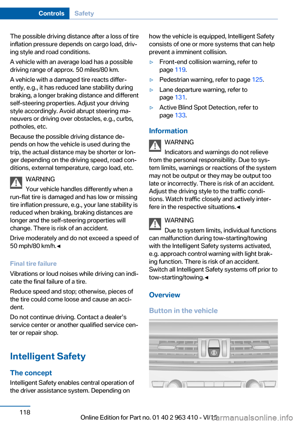
Button in the vehicle
Seite 118ControlsSafety118
Online Edition for Part no. 01 40 2 963 410 - VI/15
Page 142 of 275
The system ensures consistent comfort by
keeping spring travel constant in all driving sit‐
uations.
Malfunction
A Check Control message is displayed. The system is disrupted. Vehicle handling may be altered and driving comfort may be noticeably
reduced. Visit the nearest dealer’s service cen‐ ter or another qualified service center or repair
shop.
Driving Dynamics Control
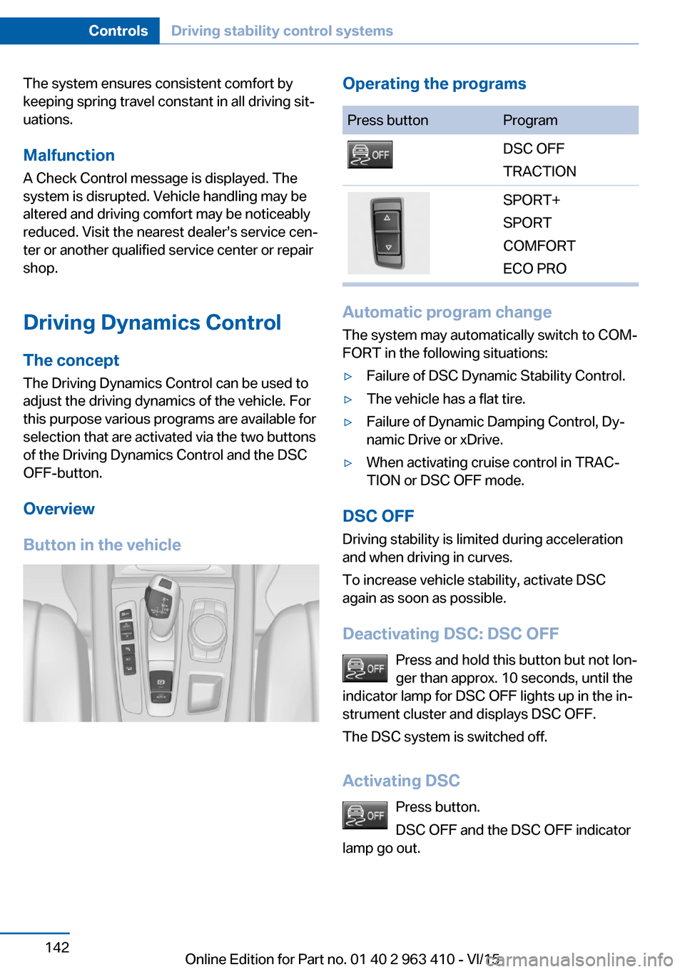
The concept The Driving Dynamics Control can be used to
adjust the driving dynamics of the vehicle. For
this purpose various programs are available for
selection that are activated via the two buttons
of the Driving Dynamics Control and the DSC
OFF-button.
Overview
Button in the vehicleOperating the programsPress buttonProgramDSC OFF
TRACTIONSPORT+
SPORT
COMFORT
ECO PRO
Automatic program change
The system may automatically switch to COM‐
FORT in the following situations:
▷Failure of DSC Dynamic Stability Control.▷The vehicle has a flat tire.▷Failure of Dynamic Damping Control, Dy‐
namic Drive or xDrive.▷When activating cruise control in TRAC‐
TION or DSC OFF mode.
DSC OFF
Driving stability is limited during acceleration
and when driving in curves.
To increase vehicle stability, activate DSC
again as soon as possible.
Deactivating DSC: DSC OFF Press and hold this button but not lon‐
ger than approx. 10 seconds, until the
indicator lamp for DSC OFF lights up in the in‐
strument cluster and displays DSC OFF.
The DSC system is switched off.
Activating DSC Press button.
DSC OFF and the DSC OFF indicator
lamp go out.
Seite 142ControlsDriving stability control systems142
Online Edition for Part no. 01 40 2 963 410 - VI/15
Page 174 of 275
Interior equipmentVehicle features and optionsThis chapter describes all standard, country-
specific and optional features offered with the
series. It also describes features that are not
necessarily available in your car, e. g., due to
the selected options or country versions. This
also applies to safety-related functions and
systems. The respectively applicable country
provisions must be observed when using the
respective features and systems.
Universal Integrated Remote Control
The concept The universal garage door opener can operate
up to 3 functions of remote-controlled sys‐
tems such as garage door drives or lighting
systems. The universal garage door opener re‐
places up to 3 different hand-held transmitters.
To operate the remote control, the buttons on
the interior rearview mirror must be program‐
med with the desired functions. The hand-held
transmitter for the particular system is required
in order to program the remote control.
Before selling the vehicle, delete the stored
functions for the sake of security.
Information WARNING
Body parts can be jammed when operat‐
ing remote-controlled systems, e.g. the garage
door, using the universal garage door opener.
There is risk of injuries or risk of property dam‐
age. Make sure that the area of movement of
the respective system is clear during program‐
ming and operation. Also follow the safety in‐
structions of the hand-held transmitter.◀Compatibility
If this symbol is printed on the packag‐
ing or in the instructions of the system
to be controlled, the system is gener‐
ally compatible with the universal garage door opener.
If you have any questions, please contact:▷A dealer’s service center or another quali‐
fied service center or repair shop.▷www.homelink.com on the Internet.
HomeLink is a registered trademark of Gentex
Corporation.
Controls on the interior rearview
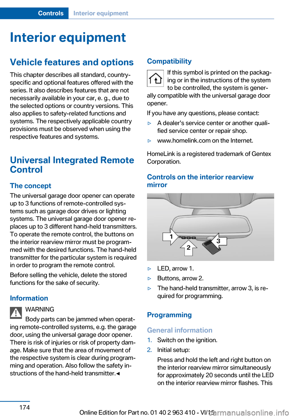
mirror
▷LED, arrow 1.▷Buttons, arrow 2.▷The hand-held transmitter, arrow 3, is re‐
quired for programming.
Programming
General information
1.Switch on the ignition.2.Initial setup:
Press and hold the left and right button on
the interior rearview mirror simultaneously
for approximately 20 seconds until the LED
on the interior rearview mirror flashes. ThisSeite 174ControlsInterior equipment174
Online Edition for Part no. 01 40 2 963 410 - VI/15
Page 200 of 275
Avoid high engine speeds
As a rule: driving at low engine speeds lowers
fuel consumption and reduces wear.
If necessary, observe the gear shift indicator of
the vehicle, refer to page 96.
Use coasting
When approaching a red light, take your foot
off the accelerator and let the vehicle coast to
a halt.
For going downhill take your foot off the accel‐
erator and let the vehicle roll.
The flow of fuel is interrupted while coasting.
Switch off the engine during longer stops
Switch off the engine during longer stops, e.g.,
at traffic lights, railroad crossings or in traffic
congestion.
Auto Start/Stop function The Auto Start/Stop function of your vehicle
automatically switches off the engine during a
stop.
If the engine is switched off and then restarted
rather than leaving the engine running con‐
stantly, fuel consumption and emissions are
reduced. Savings can begin within a few sec‐
onds of switching off the engine.
In addition, fuel consumption is also deter‐
mined by other factors, such as driving style,
road conditions, maintenance or environmental
factors.
Switch off any functions that
are not currently needed
Functions such as seat heating and the rear
window defroster require a lot of energy andreduce the range, especially in city and stop-
and-go traffic.
Switch off these functions if they are not needed.
The ECO PRO driving program supports the
energy conserving use of comfort features.
These functions are automatically deactivated
partially or completely.
Have maintenance carriedout
Have vehicles maintained regularly to achieve
optimal vehicle efficiency and service life.
BMW recommends that maintenance work be
performed by a BMW dealer’s service center.
For information on the BMW Maintenance
System, refer to page 238.
ECO PRO
The concept ECO PRO supports a driving style that saves
on fuel consumption. For this purpose, the en‐
gine control and comfort features, e. g. the cli‐
mate control output, are adjusted.
Under certain conditions the engine is auto‐
matically decoupled from the transmission in
the D selector lever position. The vehicle con‐
tinues traveling with the engine idling to re‐
duce fuel consumption. Selector lever position
D remains engaged.
In addition, context-sensitive instructions are
displayed to assist with an optimized fuel con‐
sumption driving style.
The achieved extended range is displayed in
the instrument cluster as bonus range.
Overview The system includes the following
EfficientDynamics functions and displays:▷ECO PRO bonus range, refer to page 201.Seite 200Driving tipsSaving fuel200
Online Edition for Part no. 01 40 2 963 410 - VI/15
Page 224 of 275
tolerances despite the same official size rating.
There is risk of an accident.◀
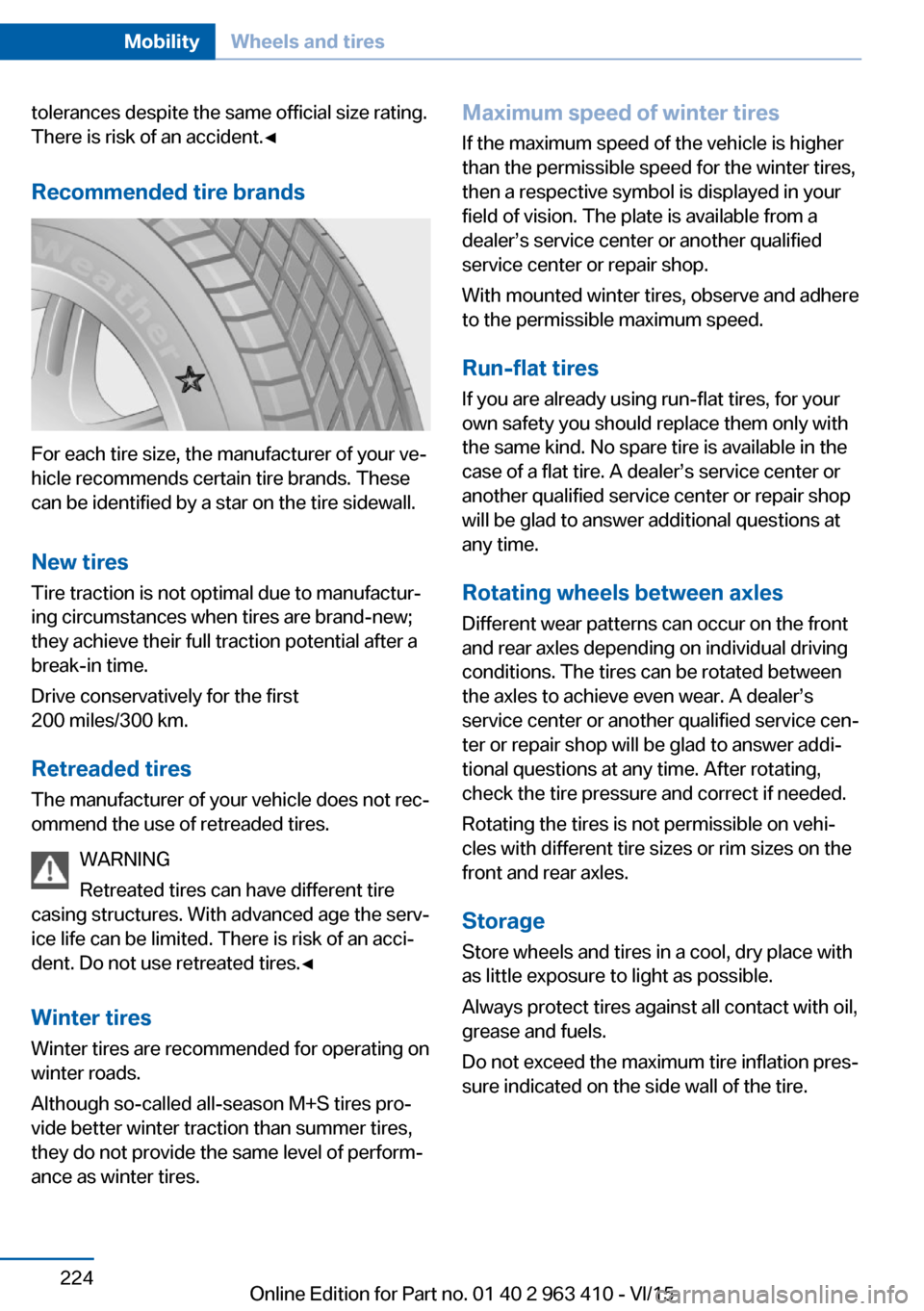
Recommended tire brands
For each tire size, the manufacturer of your ve‐
hicle recommends certain tire brands. These
can be identified by a star on the tire sidewall.
New tires
Tire traction is not optimal due to manufactur‐
ing circumstances when tires are brand-new;
they achieve their full traction potential after a
break-in time.
Drive conservatively for the first
200 miles/300 km.
Retreaded tires
The manufacturer of your vehicle does not rec‐
ommend the use of retreaded tires.
WARNING
Retreated tires can have different tire
casing structures. With advanced age the serv‐
ice life can be limited. There is risk of an acci‐
dent. Do not use retreated tires.◀
Winter tires
Winter tires are recommended for operating on winter roads.
Although so-called all-season M+S tires pro‐
vide better winter traction than summer tires,
they do not provide the same level of perform‐
ance as winter tires.
Maximum speed of winter tires
If the maximum speed of the vehicle is higher
than the permissible speed for the winter tires,
then a respective symbol is displayed in your
field of vision. The plate is available from a
dealer’s service center or another qualified
service center or repair shop.
With mounted winter tires, observe and adhere
to the permissible maximum speed.
Run-flat tires If you are already using run-flat tires, for your
own safety you should replace them only with
the same kind. No spare tire is available in the
case of a flat tire. A dealer’s service center or
another qualified service center or repair shop
will be glad to answer additional questions at
any time.
Rotating wheels between axles Different wear patterns can occur on the front
and rear axles depending on individual driving
conditions. The tires can be rotated between
the axles to achieve even wear. A dealer’s
service center or another qualified service cen‐
ter or repair shop will be glad to answer addi‐
tional questions at any time. After rotating,
check the tire pressure and correct if needed.
Rotating the tires is not permissible on vehi‐
cles with different tire sizes or rim sizes on the
front and rear axles.
Storage
Store wheels and tires in a cool, dry place with
as little exposure to light as possible.
Always protect tires against all contact with oil,
grease and fuels.
Do not exceed the maximum tire inflation pres‐
sure indicated on the side wall of the tire.Seite 224MobilityWheels and tires224
Online Edition for Part no. 01 40 2 963 410 - VI/15
Page 236 of 275
CoolantVehicle features and optionsThis chapter describes all standard, country-
specific and optional features offered with the
series. It also describes features that are not
necessarily available in your car, e. g., due to
the selected options or country versions. This
also applies to safety-related functions and
systems. The respectively applicable country
provisions must be observed when using the
respective features and systems.
Information WARNING
With the engine hot and the cooling sys‐
tem open, coolant can escape and lead to
burns. There is risk of injuries. Only open the
cooling system with the engine cooled down.◀
WARNING
Additives are harmful and incorrect addi‐
tives can damage the engine. There is risk of
injuries and risk of property damage. Avoid the
contact of articles of clothing, skin or eyes with
additives. Do not swallow any additives. Use
suitable additives only.◀
Coolant consists of water and additives.
Not all commercially available additives are
suitable for the vehicle. Information about suit‐
able additives is available from a dealer’s serv‐
ice center or another qualified service center or
repair shop.
Coolant level
General information
If there is no Min. and Max. mark in the filler
neck of the coolant reservoir, have the coolant
level checked if needed by your dealer’s serv‐ice center or another qualified service center or
repair shop and add coolant as needed.
Overview
Depending on the engine installation, the cool‐
ant reservoir is located on the right side or the
left side of the engine compartment.
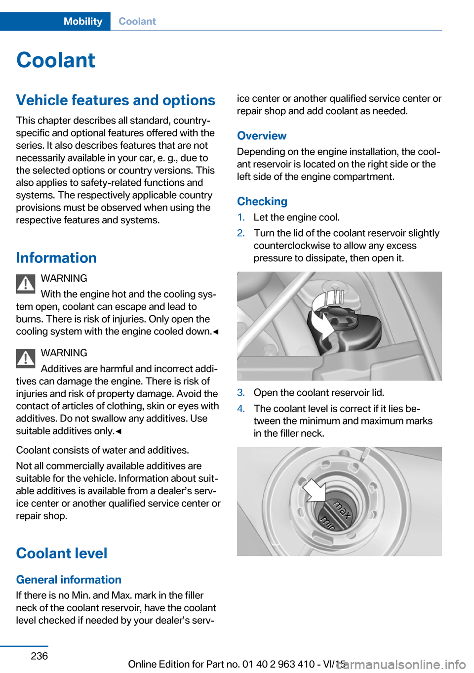
Checking1.Let the engine cool.2.Turn the lid of the coolant reservoir slightly
counterclockwise to allow any excess
pressure to dissipate, then open it.3.Open the coolant reservoir lid.4.The coolant level is correct if it lies be‐
tween the minimum and maximum marks
in the filler neck.Seite 236MobilityCoolant236
Online Edition for Part no. 01 40 2 963 410 - VI/15
Page 239 of 275
Socket for OBD Onboard
Diagnosis
Information CAUTION
Improper use of the socket for Onboard
Diagnosis can lead to vehicle malfunctions.
There is risk of property damage. The manu‐
facturer of your vehicle strongly recommends
access to the socket for Onboard Diagnosis be
limited to a dealer's service center, another
qualified service center or repair shop or other
authorized persons.◀
Position
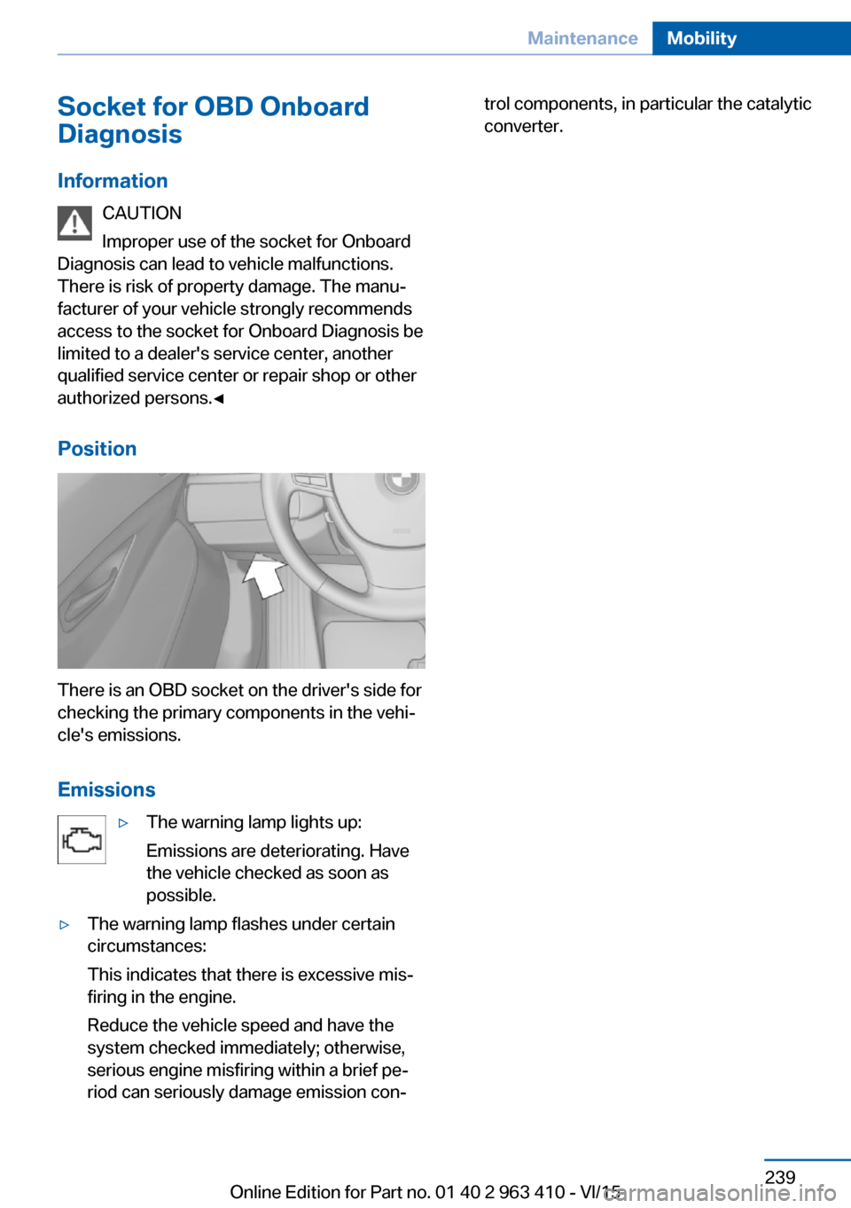
There is an OBD socket on the driver's side for
checking the primary components in the vehi‐
cle's emissions.
Emissions
▷The warning lamp lights up:
Emissions are deteriorating. Have
the vehicle checked as soon as
possible.▷The warning lamp flashes under certain
circumstances:
This indicates that there is excessive mis‐
firing in the engine.
Reduce the vehicle speed and have the
system checked immediately; otherwise,
serious engine misfiring within a brief pe‐
riod can seriously damage emission con‐trol components, in particular the catalytic
converter.Seite 239MaintenanceMobility239
Online Edition for Part no. 01 40 2 963 410 - VI/15
Page 241 of 275
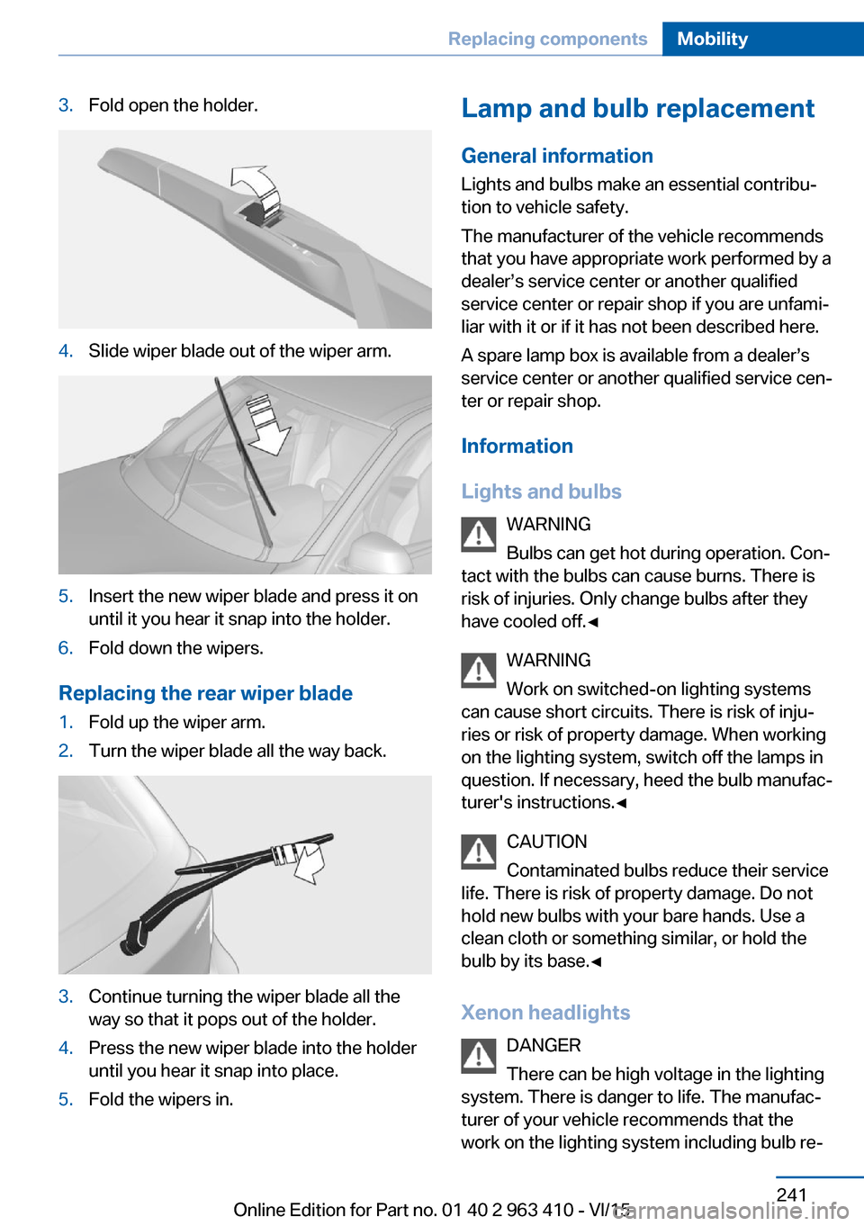
3.Fold open the holder.4.Slide wiper blade out of the wiper arm.5.Insert the new wiper blade and press it on
until it you hear it snap into the holder.6.Fold down the wipers.
Replacing the rear wiper blade
1.Fold up the wiper arm.2.Turn the wiper blade all the way back.3.Continue turning the wiper blade all the
way so that it pops out of the holder.4.Press the new wiper blade into the holder
until you hear it snap into place.5.Fold the wipers in.Lamp and bulb replacement
General information
Lights and bulbs make an essential contribu‐
tion to vehicle safety.
The manufacturer of the vehicle recommends
that you have appropriate work performed by a
dealer’s service center or another qualified
service center or repair shop if you are unfami‐
liar with it or if it has not been described here.
A spare lamp box is available from a dealer’s
service center or another qualified service cen‐
ter or repair shop.
Information
Lights and bulbs WARNING
Bulbs can get hot during operation. Con‐
tact with the bulbs can cause burns. There is
risk of injuries. Only change bulbs after they
have cooled off.◀
WARNING
Work on switched-on lighting systems
can cause short circuits. There is risk of inju‐
ries or risk of property damage. When working
on the lighting system, switch off the lamps in
question. If necessary, heed the bulb manufac‐
turer's instructions.◀
CAUTION
Contaminated bulbs reduce their service
life. There is risk of property damage. Do not
hold new bulbs with your bare hands. Use a
clean cloth or something similar, or hold the
bulb by its base.◀
Xenon headlights DANGER
There can be high voltage in the lighting
system. There is danger to life. The manufac‐
turer of your vehicle recommends that the
work on the lighting system including bulb re‐Seite 241Replacing componentsMobility241
Online Edition for Part no. 01 40 2 963 410 - VI/15