change wheel BMW X6 2016 F16 User Guide
[x] Cancel search | Manufacturer: BMW, Model Year: 2016, Model line: X6, Model: BMW X6 2016 F16Pages: 265, PDF Size: 6.17 MB
Page 112 of 265
longer and the self-steering properties will
change. There is risk of an accident.
Drive moderately and do not exceed a speed of
50 mph/80 km/h.◀
Final tire failure
Vibrations or loud noises while driving can indi‐
cate the final failure of a tire.
Reduce speed and stop; otherwise, pieces of
the tire could come loose and cause an acci‐
dent.
Do not continue driving. Contact a dealer’s
service center or another qualified service cen‐
ter or repair shop.
Required tire inflation pressure check
message
A Check Control message is displayed in the
following situations▷The system has detected a wheel change,
but no reset was done.▷Inflation was not carried out according to
specifications.▷The tire inflation pressure has fallen below
the level of the last confirmation.
In this case:
▷Check the tire pressure and correct as
needed.▷Carry out a reset of the system after a tire
change.
System limits
The system does not function properly if a re‐
set has not been carried out, e.g., a flat tire is
reported though tire inflation pressures are
correct.
The tire inflation pressure depends on the
tire's temperature. Driving or exposure to the
sun will increase the tire's temperature, thus
increasing the tire inflation pressure. The tire
inflation pressure is reduced when the tire
temperature falls again. These circumstances
may cause a warning when temperatures fall
very sharply.
The system cannot indicate sudden serious
tire damage caused by external circumstances.
Malfunction The yellow warning lamp flashes and
then lights up continuously. A Check
Control message is displayed. No flat
tire or loss of tire inflation pressure can be de‐
tected.
Examples and recommendations in the follow‐
ing situations:▷A wheel without TPM electronics is
mounted: Have it checked by a dealer’s
service center or another qualified service
center or repair shop as needed.▷Malfunction: Have system checked by a
dealer’s service center or another qualified
service center or repair shop.▷TPM was unable to complete the reset.
Reset the system again.▷Interference through systems or devices
with the same radio frequency: After leav‐
ing the area of the interference, the system
automatically becomes active again.
Declaration according to NHTSA/
FMVSS 138 Tire Pressure Monitoring
System
Each tire, including the spare (if provided)
should be checked monthly when cold and in‐
flated to the inflation pressure recommended
by the vehicle manufacturer on the vehicle
placard or tire inflation pressure label. (If your
vehicle has tires of a different size than the size
indicated on the vehicle placard or tire inflation
pressure label, you should determine the
proper tire inflation pressure for those tires.)
As an added safety feature, your vehicle has
been equipped with a tire pressure monitoring
system (TPMS) that illuminates a low tire pres‐
sure telltale when one or more of your tires is
significantly under-inflated. Accordingly, when
Seite 112ControlsSafety112
Online Edition for Part no. 01 40 2 963 464 - VI/15
Page 113 of 265
the low tire pressure telltale illuminates, you
should stop and check your tires as soon as
possible, and inflate them to the proper pres‐
sure. Driving on a significantly under-inflated
tire causes the tire to overheat and can lead to
tire failure. Under-inflation also reduces fuel ef‐
ficiency and tire tread life, and may affect the
vehicle's handling and stopping ability. Please
note that the TPMS is not a substitute for
proper tire maintenance, and it is the driver's
responsibility to maintain correct tire pressure,
even if under-inflation has not reached the
level to trigger illumination of the TPMS low
tire pressure telltale. Your vehicle has also
been equipped with a TPMS malfunction indi‐
cator to indicate when the system is not oper‐
ating properly. The TPMS malfunction indica‐
tor is combined with the low tire pressure
telltale. When the system detects a malfunc‐
tion, the telltale will flash for approximately one
minute and then remain continuously illumi‐
nated. This sequence will continue upon sub‐
sequent vehicle start-ups as long as the mal‐
function exists. When the malfunction indicator
is illuminated, the system may not be able to
detect or signal low tire pressure as intended.
TPMS malfunctions may occur for a variety of
reasons, including the installation of replace‐
ment or alternate tires or wheels on the vehicle
that prevent the TPMS from functioning prop‐
erly. Always check the TPMS malfunction tell‐
tale after replacing one or more tires or wheels
on your vehicle to ensure that the replacement
or alternate tires and wheels allow the TPMS
to continue to function properly.
FTM Flat Tire Monitor The conceptThe system detects tire inflation pressure losson the basis of rotation speed differences be‐
tween the individual wheels while driving.
In the event of a tire inflation pressure loss, the
diameter and therefore the rotational speed ofthe corresponding wheel changes. This will be
detected and reported as a flat tire.
The system does not measure the actual infla‐
tion pressure in the tires.
Functional requirements
The system must have been initialized when
the tire inflation pressure was correct; other‐
wise, reliable flagging of a flat tire is not as‐
sured. Initialize the system after each correc‐ tion of the tire inflation pressure and after
every tire or wheel change.
Status display
The current status of the Flat Tire Monitor can
be displayed on the Control Display, e.g.,
whether or not the FTM is active.
On the Control Display:1."Vehicle info"2."Vehicle status"3. "Flat Tire Monitor (FTM)"
The status is displayed.
Initialization
When initializing the once set inflation tire
pressures serve as reference values in order to
detect a flat tire. Initialization is started by con‐
firming the tire inflation pressures.
Do not initialize the system when driving with
snow chains.
On the Control Display:
1."Vehicle info"2."Vehicle status"3. "Perform reset"4.Start the engine - do not drive off.5.Start the initialization with "Perform reset".6.Drive away.
The initialization is completed while driving,
which can be interrupted at any time.
The initialization automatically continues when
driving resumes.
Seite 113SafetyControls113
Online Edition for Part no. 01 40 2 963 464 - VI/15
Page 130 of 265
Active Blind Spot Detection
The concept
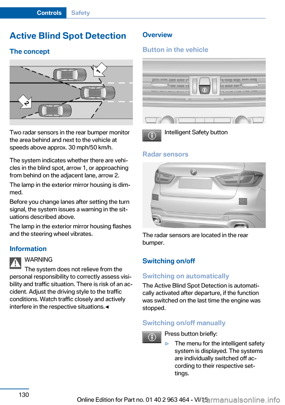
Two radar sensors in the rear bumper monitor
the area behind and next to the vehicle at
speeds above approx. 30 mph/50 km/h.
The system indicates whether there are vehi‐
cles in the blind spot, arrow 1, or approaching
from behind on the adjacent lane, arrow 2.
The lamp in the exterior mirror housing is dim‐
med.
Before you change lanes after setting the turn
signal, the system issues a warning in the sit‐
uations described above.
The lamp in the exterior mirror housing flashes
and the steering wheel vibrates.
Information WARNING
The system does not relieve from the
personal responsibility to correctly assess visi‐
bility and traffic situation. There is risk of an ac‐
cident. Adjust the driving style to the traffic
conditions. Watch traffic closely and actively interfere in the respective situations.◀
Overview
Button in the vehicle
Intelligent Safety button
Radar sensors
The radar sensors are located in the rear
bumper.
Switching on/off
Switching on automatically The Active Blind Spot Detection is automati‐
cally activated after departure, if the function
was switched on the last time the engine was
stopped.
Switching on/off manually Press button briefly:
▷The menu for the intelligent safety
system is displayed. The systems
are individually switched off ac‐
cording to their respective set‐
tings.Seite 130ControlsSafety130
Online Edition for Part no. 01 40 2 963 464 - VI/15
Page 131 of 265
▷LED lights up orange or goes out respec‐
tive to their individual settings.
Adjust as needed. Individual settings are
stored for the profile currently used.
Press button again:
▷All Intelligent Safety systems are
activated.▷The LED lights up green.
Hold down button:
▷All Intelligent Safety systems are
turned off.▷The LED goes out.
Display
Lamp in the exterior mirror housing
Information stage
The dimmed lamp in the exterior mirror hous‐
ing indicates when there are vehicles in the
blind spot or approaching from behind.
WARNING If the turn signal is set while a vehicle is in the
critical zone, the steering wheel vibrates briefly
and the lamp in the exterior mirror housing
flashes brightly.
The warning stops when the turn signal is
switched off, or the other vehicle leaves the
critical zone.
Brief flashing
A brief flashing of the lamp during vehicle un‐
locking serves as system self-test.
System limits
The system may not be fully functional in the
following situations:▷When a vehicle is approaching at a speed
much faster than your own.▷In heavy fog, rain or snowfall.▷In tight curves or on narrow lanes.▷If the bumper is dirty or iced up, or covered
with stickers.
A Check Control message is displayed when
the system is not fully functional.
For US owners only The transmitter and receiver units comply with
part 15 of the FCC/Federal Communication
Commission regulations. Operation is gov‐
erned by the following:
FCC ID:
▷NBG009014A.
Compliance statement:
This device complies with part 15 of the FCC
Rules. Operation is subject to the following
two conditions:
▷This device may not cause harmful inter‐
ference, and▷this device must accept any interference
received, including interference that may
cause undesired operation.
Any unauthorized modifications or changes to
these devices could void the user's authority to
operate this equipment.
Seite 131SafetyControls131
Online Edition for Part no. 01 40 2 963 464 - VI/15
Page 137 of 265
Displaying distribution of the drive
torque1."Vehicle info"2."xDrive status"3. "Torque distribution"
HDC Hill Descent Control
The concept HDC is a downhill driving assistant that auto‐
matically controls vehicle speed on steep
downhill gradients. Without applying the
brakes, the vehicle moves at slightly more than
walking speed.
Hill Descent Control can be activated at
speeds below approx. 22 mph/35 km/h. When
driving downhill, the vehicle reduces its speed
to approx. walking speed and then keeps its
speed constant.
As long as there is active braking, the system
is on standby. The system does not brake the
vehicle during this time.
Only use HDC in low gears or in selector lever
position D or R.
Increasing or decreasing vehicle
speed
Specify desired speed in the range from ap‐
prox. 4 mph/6 km/h to approx. 15 mph/25 km/h
using the rocker switch of the cruise control on
the steering wheel. Vehicle speed can be
changed by lightly accelerating.
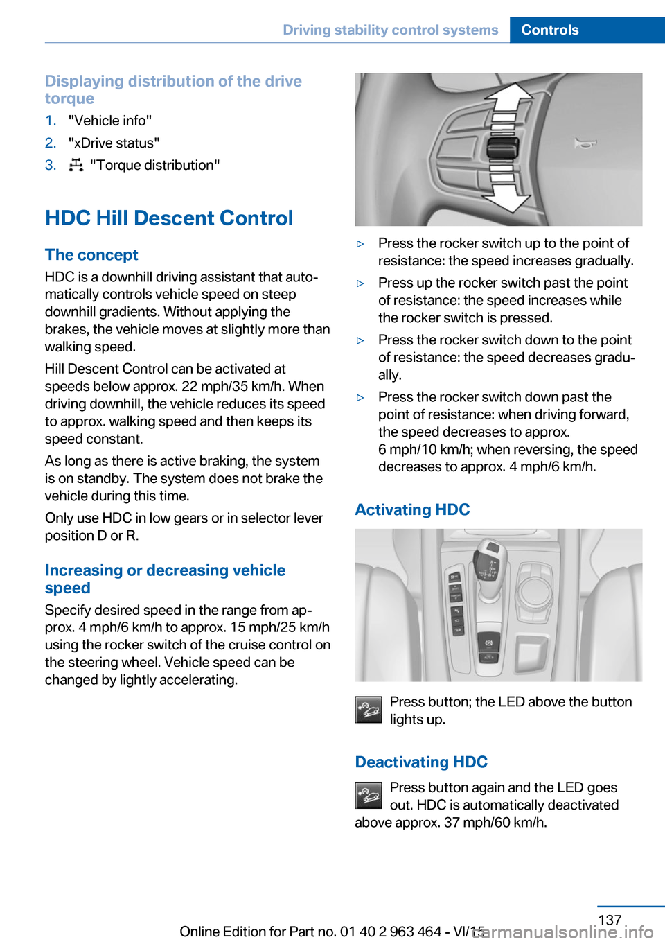
▷Press the rocker switch up to the point of
resistance: the speed increases gradually.▷Press up the rocker switch past the point
of resistance: the speed increases while
the rocker switch is pressed.▷Press the rocker switch down to the point
of resistance: the speed decreases gradu‐
ally.▷Press the rocker switch down past the
point of resistance: when driving forward,
the speed decreases to approx.
6 mph/10 km/h; when reversing, the speed
decreases to approx. 4 mph/6 km/h.
Activating HDC
Press button; the LED above the button
lights up.
Deactivating HDC Press button again and the LED goes
out. HDC is automatically deactivated
above approx. 37 mph/60 km/h.
Seite 137Driving stability control systemsControls137
Online Edition for Part no. 01 40 2 963 464 - VI/15
Page 142 of 265
Driving comfortVehicle features and options
This chapter describes all standard, country-
specific and optional features offered with the
series. It also describes features that are not
necessarily available in your car, e. g., due to
the selected options or country versions. This
also applies to safety-related functions and
systems. The respectively applicable country
provisions must be observed when using the
respective features and systems.
Active Cruise Control with Stop & Go function, ACC
The concept
Use this system to select a desired speed that
the vehicle will maintain automatically on clear
roads.
To the extent possible, the system automati‐
cally adjusts the speed to a slower vehicle
ahead of you.
The distance that the vehicle maintains to the
vehicle ahead of you can be varied.
For safety reasons, it depends on the speed.
To maintain a certain distance, the system au‐
tomatically reduces the speed, applies the
brakes lightly, or accelerates again if the vehi‐
cle ahead begins moving faster.
If the vehicle ahead of you brakes to a halt, and
then proceeds to drive again within a brief pe‐
riod, the system is able to detect this within the
given system limits. Your own vehicle will
brake automatically and then accelerate again.
If the vehicle ahead of you drives away again
after a prolonged period, briefly press the ac‐
celerator pedal or press the appropriate button
to reactivate the system. The vehicle will auto‐
matically accelerate.As soon as the road is clear, the vehicle accel‐
erates to the desired speed.
The speed is also maintained downhill, but
may not be maintained uphill if engine power is
insufficient.
General information
Depending on the driving settings, the features
of the cruise control can change in certain
areas.
Information WARNING
The system does not relieve from the
personal responsibility to correctly assess the
traffic situation. Based on the limits of the sys‐
tem, it cannot independently react to all traffic
situations. There is risk of an accident. Adjust
the driving style to the traffic conditions. Watch
traffic closely and actively interfere in the re‐
spective situations.◀
WARNING
An unsecured vehicle can put itself into
motion and roll away. There is risk of an acci‐
dent. Before exiting, secure the vehicle against
rolling.
In order to ensure that the vehicle is secured
against rolling away, observe the following:▷Set the parking brake.▷On uphill grades or on a slope, turn the
front wheels in the direction of the curb.▷On uphill grades or on a slope, also secure
the vehicle, e.g. with a wheel chock.◀Seite 142ControlsDriving comfort142
Online Edition for Part no. 01 40 2 963 464 - VI/15
Page 143 of 265
Overview
Buttons on the steering wheelPress but‐
tonFunctionCruise control on/off, interrupt,
refer to page 143Store/maintain speed, refer to
page 144Resume speed, refer to
page 145Reduce distance, refer to
page 145Increase distance, refer to
page 145Rocker switch:
Maintain, store, change speed,
refer to page 144
Buttons are arranged according to vehicle's
series, optional features and country specifica‐
tions.
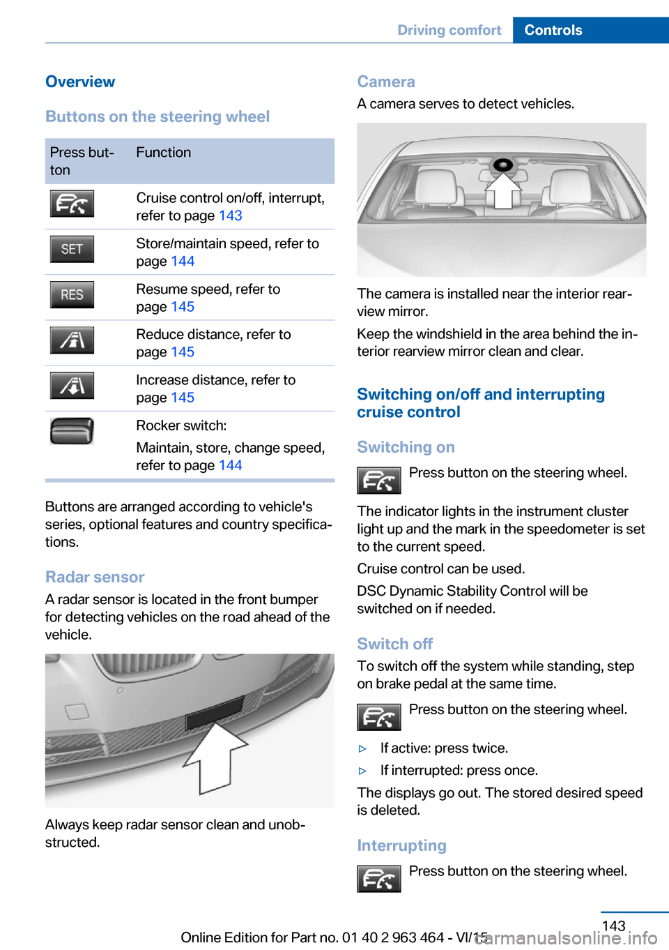
Radar sensor
A radar sensor is located in the front bumper for detecting vehicles on the road ahead of the
vehicle.
Always keep radar sensor clean and unob‐
structed.
Camera
A camera serves to detect vehicles.
The camera is installed near the interior rear‐
view mirror.
Keep the windshield in the area behind the in‐
terior rearview mirror clean and clear.
Switching on/off and interrupting
cruise control
Switching on Press button on the steering wheel.
The indicator lights in the instrument cluster
light up and the mark in the speedometer is set
to the current speed.
Cruise control can be used.
DSC Dynamic Stability Control will be
switched on if needed.
Switch off To switch off the system while standing, step
on brake pedal at the same time.
Press button on the steering wheel.
▷If active: press twice.▷If interrupted: press once.
The displays go out. The stored desired speed
is deleted.
Interrupting Press button on the steering wheel.
Seite 143Driving comfortControls143
Online Edition for Part no. 01 40 2 963 464 - VI/15
Page 148 of 265
Cornering
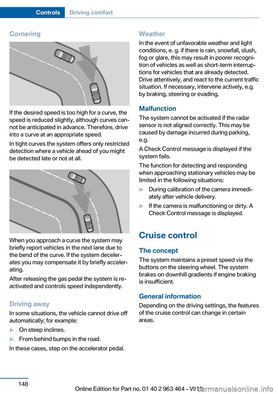
If the desired speed is too high for a curve, the
speed is reduced slightly, although curves can‐
not be anticipated in advance. Therefore, drive
into a curve at an appropriate speed.
In tight curves the system offers only restricted
detection where a vehicle ahead of you might
be detected late or not at all.
When you approach a curve the system may
briefly report vehicles in the next lane due to
the bend of the curve. If the system deceler‐
ates you may compensate it by briefly acceler‐
ating.
After releasing the gas pedal the system is re‐
activated and controls speed independently.
Driving away In some situations, the vehicle cannot drive off
automatically; for example:
▷On steep inclines.▷From behind bumps in the road.
In these cases, step on the accelerator pedal.
Weather
In the event of unfavorable weather and light conditions, e. g. if there is rain, snowfall, slush,
fog or glare, this may result in poorer recogni‐
tion of vehicles as well as short-term interrup‐
tions for vehicles that are already detected. Drive attentively, and react to the current trafficsituation. If necessary, intervene actively, e.g.
by braking, steering or evading.
Malfunction
The system cannot be activated if the radar sensor is not aligned correctly. This may be
caused by damage incurred during parking,
e.g.
A Check Control message is displayed if the
system fails.
The function for detecting and responding
when approaching stationary vehicles may be limited in the following situations:▷During calibration of the camera immedi‐
ately after vehicle delivery.▷If the camera is malfunctioning or dirty. A
Check Control message is displayed.
Cruise control
The concept The system maintains a preset speed via the
buttons on the steering wheel. The system
brakes on downhill gradients if engine braking
is insufficient.
General information
Depending on the driving settings, the features
of the cruise control can change in certain
areas.
Seite 148ControlsDriving comfort148
Online Edition for Part no. 01 40 2 963 464 - VI/15
Page 149 of 265
InformationWARNING
The use of the system can lead to an in‐
creased risk of accidents in the following situa‐
tions:▷On winding roads.▷In heavy traffic.▷On slippery roads, in fog, snow or rain, or
on a loose road surface.
There is risk of accidents or risk of property
damage. Only use the system if driving at con‐
stant speed is possible.◀
Overview
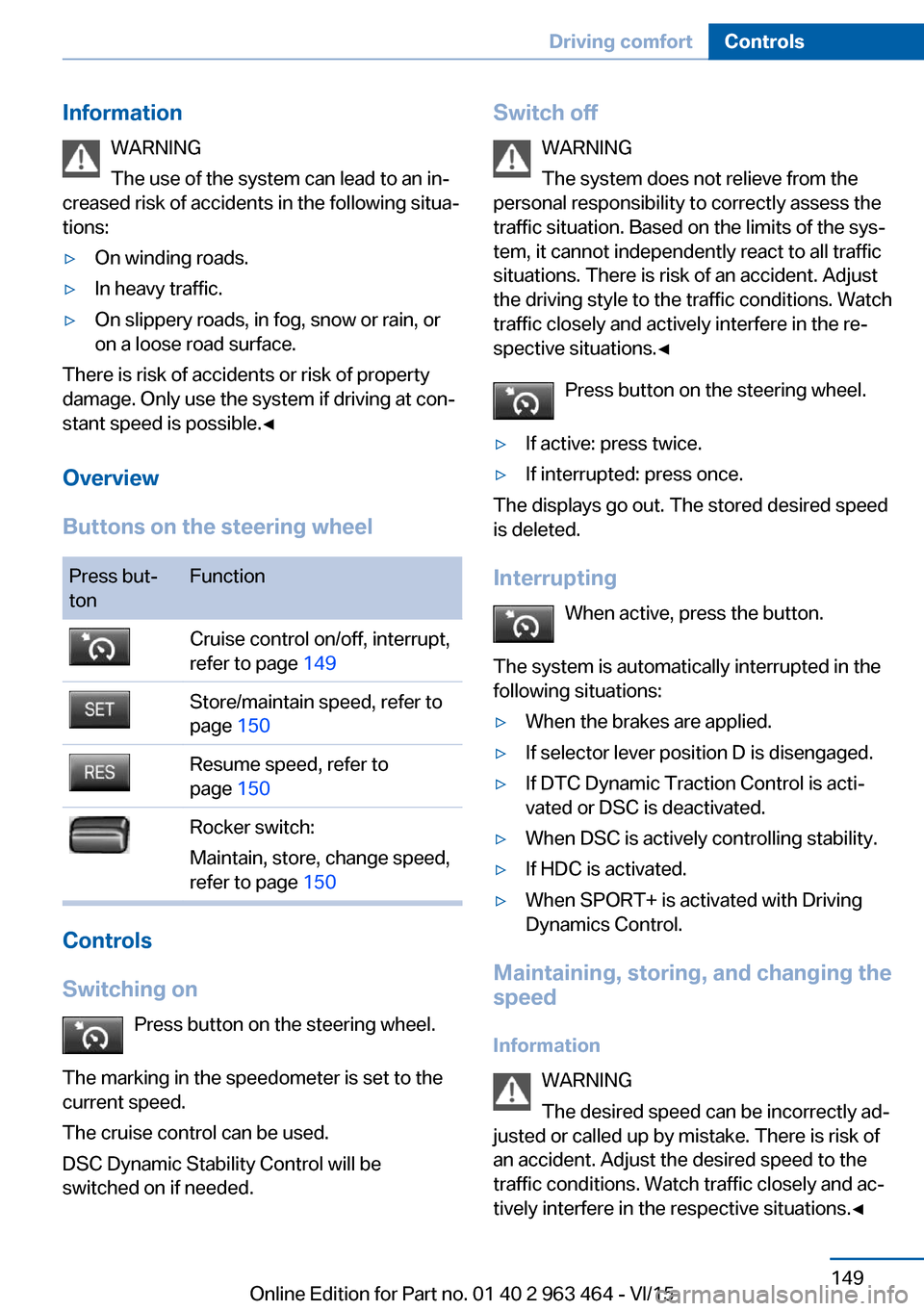
Buttons on the steering wheel
Press but‐
tonFunctionCruise control on/off, interrupt,
refer to page 149Store/maintain speed, refer to
page 150Resume speed, refer to
page 150Rocker switch:
Maintain, store, change speed,
refer to page 150
Controls
Switching on Press button on the steering wheel.
The marking in the speedometer is set to the
current speed.
The cruise control can be used.
DSC Dynamic Stability Control will be
switched on if needed.
Switch off
WARNING
The system does not relieve from the
personal responsibility to correctly assess the
traffic situation. Based on the limits of the sys‐
tem, it cannot independently react to all traffic situations. There is risk of an accident. Adjustthe driving style to the traffic conditions. Watch
traffic closely and actively interfere in the re‐
spective situations.◀
Press button on the steering wheel.▷If active: press twice.▷If interrupted: press once.
The displays go out. The stored desired speed
is deleted.
Interrupting When active, press the button.
The system is automatically interrupted in the
following situations:
▷When the brakes are applied.▷If selector lever position D is disengaged.▷If DTC Dynamic Traction Control is acti‐
vated or DSC is deactivated.▷When DSC is actively controlling stability.▷If HDC is activated.▷When SPORT+ is activated with Driving
Dynamics Control.
Maintaining, storing, and changing the
speed
Information WARNING
The desired speed can be incorrectly ad‐
justed or called up by mistake. There is risk of
an accident. Adjust the desired speed to the
traffic conditions. Watch traffic closely and ac‐
tively interfere in the respective situations.◀
Seite 149Driving comfortControls149
Online Edition for Part no. 01 40 2 963 464 - VI/15
Page 167 of 265
Switching on1.Switch off the ignition.2. Press the right side of the button
on the driver's side.
The symbol appears on the automatic cli‐
mate Control Display.
The interior temperature, air volume and air
distribution can be adjusted with the ignition
switched on.
Switch off
At the lowest fan speed, press the left side of
the button on the driver's side.
The symbol on the display of the automatic
climate control flashes.
Defrosts windows and removes
condensation
Press button.
Ice and condensation are quickly re‐
moved from the windshield and the front side
windows.
For this purpose, point the side vents onto the
side windows as needed.
Adjust air flow with the program active.
If the windows are fogged over, you can also
switch on the cooling function or press the AUTO button to utilize the condensation sen‐
sor.
Rear window defroster Press button.
The rear window defroster switches
off automatically after a certain period of time.
Microfilter/activated-charcoal filter
The microfilter removes dust and pollen from
the incoming air.
The activated-charcoal filter removes gaseous
pollutants from the outside air that enters the
vehicle.
This combined filter should be replaced during
scheduled maintenance, refer to page 228, of
your vehicle.
Ventilation
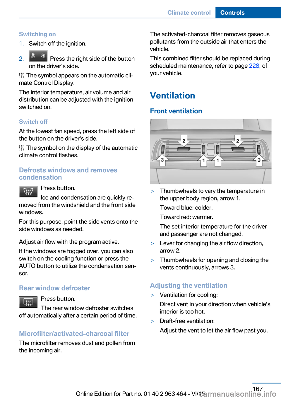
Front ventilation▷Thumbwheels to vary the temperature in
the upper body region, arrow 1.
Toward blue: colder.
Toward red: warmer.
The set interior temperature for the driver
and passenger are not changed.▷Lever for changing the air flow direction,
arrow 2.▷Thumbwheels for opening and closing the
vents continuously, arrows 3.
Adjusting the ventilation
▷Ventilation for cooling:
Direct vent in your direction when vehicle's
interior is too hot.▷Draft-free ventilation:
Adjust the vent to let the air flow past you.Seite 167Climate controlControls167
Online Edition for Part no. 01 40 2 963 464 - VI/15