BMW X6 XDRIVE 35I 2014 Owners Manual
Manufacturer: BMW, Model Year: 2014, Model line: X6 XDRIVE 35I, Model: BMW X6 XDRIVE 35I 2014Pages: 323, PDF Size: 8.36 MB
Page 91 of 323
indicated despite correct tire inflation pres‐
sures.
The system is inactive and cannot indicate a
flat tire:▷If a wheel without TPM electronics is
mounted, e.g., compact wheel.▷When the TPM is disturbed by other sys‐
tems or devices with the same radio fre‐
quency.
Status display
1."Vehicle Info"2."Vehicle status"3. "TPM"
The status is displayed.
Status indicator on the Control
Display
The tire and system status is indicated by the
color of the tires.
A change in the tire inflation pressure during
driving is taken into account.
A correction is only necessary if this is indi‐
cated by the TPM
Wheels, green
The tire inflation pressure is equal to the target
state.
One wheel is yellow A flat tire or major drop in inflation pressure in
the indicated tire.
All wheels are yellow
▷A flat tire or major drop in inflation pressure
in several tires.▷The system was not reset after a wheel
change and thus issues a warning based
on the inflation pressures initialized last.▷A flat tire in one or more tires while the sys‐
tem is being reset.Wheels, gray
The system cannot detect a flat tire.
Reasons for this may be:▷TPM is being reset.▷Disturbance by systems or devices with
the same radio frequency.▷Malfunction.
Resetting the system
Reset the system after each correction of the
tire inflation pressure and after every tire or
wheel change.
1."Vehicle Info"2."Vehicle status"3. "Reset"4.Start the engine - do not drive away.5.Reset the tire pressure using "Reset".6.Drive away.
The tires are shown in gray and "Resetting
TPM..." is displayed.
After driving for a few minutes, the set tire in‐
flation pressures are applied as set values. The
resetting process is completed automatically
as you drive. The tires are shown in green and
"TPM active" is shown on the Control Display.
The trip can be interrupted at any time. If you
drive away again, the process resumes auto‐
matically. Do not reset the system when driv‐
ing with a compact wheel.
If a flat tire is detected while the system is re‐
setting, all tires on the Control Display are dis‐
played in yellow. The message "Low tire!" is
shown.
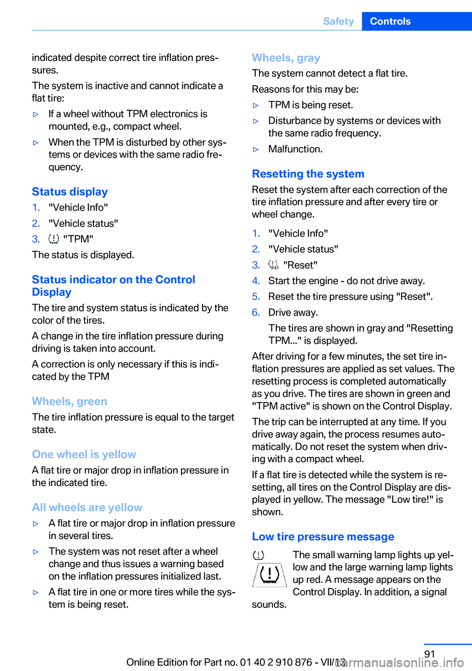
Low tire pressure message The small warning lamp lights up yel‐
low and the large warning lamp lights
up red. A message appears on the
Control Display. In addition, a signal
sounds.
Seite 91SafetyControls91
Online Edition for Part no. 01 40 2 910 876 - VII/13
Page 92 of 323
▷There is a flat tire or a major loss in tire in‐
flation pressure.▷The system was not reset after a wheel
change and thus issues warnings based on
the inflation pressures initialized last.
Reduce your speed and stop cautiously. Avoid
sudden braking and steering maneuvers.
Do not continue driving without run-flat
tires
If the vehicle is not equipped with run-flat tires
as provided at the factory, do not continue
driving. Continuing to drive could cause severe
accidents.◀
When a low inflation pressure is indicated,
DSC Dynamic Stability Control is switched on
if necessary.
Actions in the event of a flat tire Run-flat tires Maximum speed
You can continue driving with a damaged tire
at speeds up to 50 mph/80 km/h.
Continued driving with a flat tire
If continuing to drive with a damaged tire:
1.Avoid sudden braking and steering maneu‐
vers.2.Do not exceed a speed of 50 mph/80 km/h.3.Check the air pressure in all four tires at
the next opportunity.
If the tire inflation pressure in all four tires
is correct, the Tire Pressure Monitor may
not have been reset. Reset the system.
Possible driving distance with complete loss of
tire inflation pressure:
The possible driving distance after a loss of tire
inflation pressure depends on the cargo load
and the driving style and conditions.
For a vehicle containing an average load, the
possible driving distance is ap‐
prox. 50 miles/80 km.
When the vehicle is driven with a damaged tire,
its handling characteristics change, e.g., re‐
duced lane stability during braking, a longer
braking distance, and altered self-steering
properties. Adjust your driving style accord‐
ingly. Avoid abrupt steering maneuvers or driv‐
ing over obstacles, e. g., curbs, potholes, etc.
Because the possible driving distance de‐
pends on how the vehicle is used during the
trip, the actual distance may be smaller or
greater depending on the driving speed, road
conditions, external temperature, cargo load,
etc.
Continued driving with a flat tire
Drive moderately and do not exceed a
speed of 50 mph/80 km/h.
A loss of tire inflation pressure results in a
change in the handling characteristics, e.g., re‐
duced lane stability during braking, a longer
braking distance and altered self-steering
properties.◀
Final tire failure
Vibrations or loud noises while driving
can indicate the final failure of the tire. Reduce
speed and stop; otherwise, pieces of the tire
could come loose and cause an accident. Do
not continue driving, and contact your service
center.◀
Message when the system was not
reset
The yellow warning lamp lights up. A
message appears on the Control Dis‐
play.
The system detected a wheel change but was
not reset.
Warnings regarding the current tire inflation
pressure are not reliable.Seite 92ControlsSafety92
Online Edition for Part no. 01 40 2 910 876 - VII/13
Page 93 of 323
Check the tire inflation pressure and reset the
system.
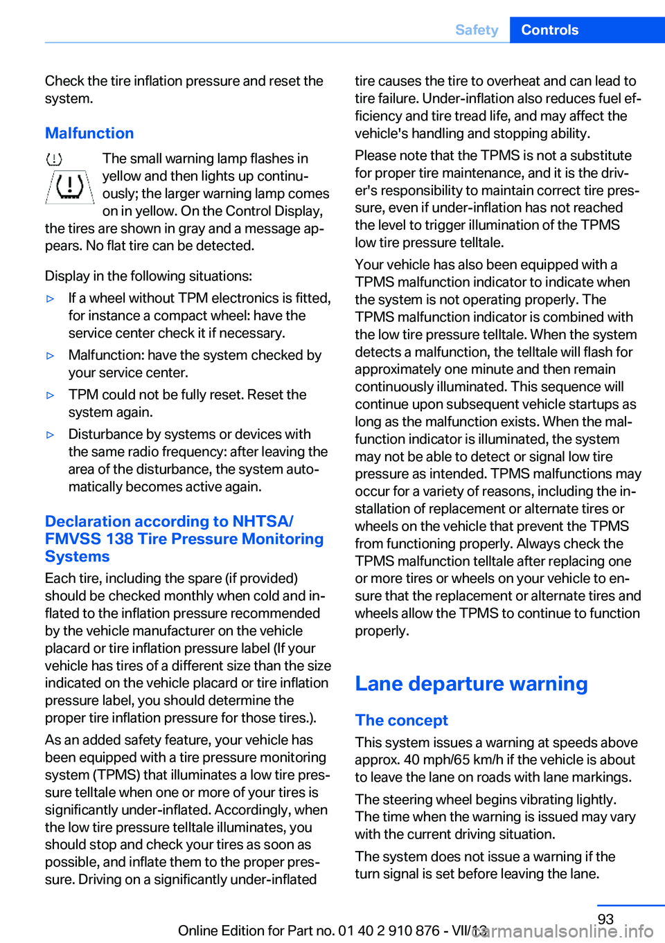
Malfunction The small warning lamp flashes inyellow and then lights up continu‐
ously; the larger warning lamp comes
on in yellow. On the Control Display,
the tires are shown in gray and a message ap‐
pears. No flat tire can be detected.
Display in the following situations:▷If a wheel without TPM electronics is fitted,
for instance a compact wheel: have the
service center check it if necessary.▷Malfunction: have the system checked by
your service center.▷TPM could not be fully reset. Reset the
system again.▷Disturbance by systems or devices with
the same radio frequency: after leaving the
area of the disturbance, the system auto‐
matically becomes active again.
Declaration according to NHTSA/
FMVSS 138 Tire Pressure Monitoring
Systems
Each tire, including the spare (if provided)
should be checked monthly when cold and in‐
flated to the inflation pressure recommended
by the vehicle manufacturer on the vehicle
placard or tire inflation pressure label (If your
vehicle has tires of a different size than the size
indicated on the vehicle placard or tire inflation
pressure label, you should determine the
proper tire inflation pressure for those tires.).
As an added safety feature, your vehicle has
been equipped with a tire pressure monitoring
system (TPMS) that illuminates a low tire pres‐
sure telltale when one or more of your tires is
significantly under-inflated. Accordingly, when
the low tire pressure telltale illuminates, you
should stop and check your tires as soon as
possible, and inflate them to the proper pres‐
sure. Driving on a significantly under-inflated
tire causes the tire to overheat and can lead to
tire failure. Under-inflation also reduces fuel ef‐
ficiency and tire tread life, and may affect the
vehicle's handling and stopping ability.
Please note that the TPMS is not a substitute
for proper tire maintenance, and it is the driv‐
er's responsibility to maintain correct tire pres‐
sure, even if under-inflation has not reached
the level to trigger illumination of the TPMS
low tire pressure telltale.
Your vehicle has also been equipped with a
TPMS malfunction indicator to indicate when
the system is not operating properly. The
TPMS malfunction indicator is combined with
the low tire pressure telltale. When the system
detects a malfunction, the telltale will flash for
approximately one minute and then remain
continuously illuminated. This sequence will
continue upon subsequent vehicle startups as
long as the malfunction exists. When the mal‐
function indicator is illuminated, the system
may not be able to detect or signal low tire
pressure as intended. TPMS malfunctions may
occur for a variety of reasons, including the in‐
stallation of replacement or alternate tires or
wheels on the vehicle that prevent the TPMS
from functioning properly. Always check the
TPMS malfunction telltale after replacing one
or more tires or wheels on your vehicle to en‐
sure that the replacement or alternate tires and
wheels allow the TPMS to continue to function
properly.
Lane departure warning
The concept This system issues a warning at speeds above
approx. 40 mph/65 km/h if the vehicle is about
to leave the lane on roads with lane markings.
The steering wheel begins vibrating lightly.
The time when the warning is issued may vary
with the current driving situation.
The system does not issue a warning if the
turn signal is set before leaving the lane.Seite 93SafetyControls93
Online Edition for Part no. 01 40 2 910 876 - VII/13
Page 94 of 323
Switching on/off
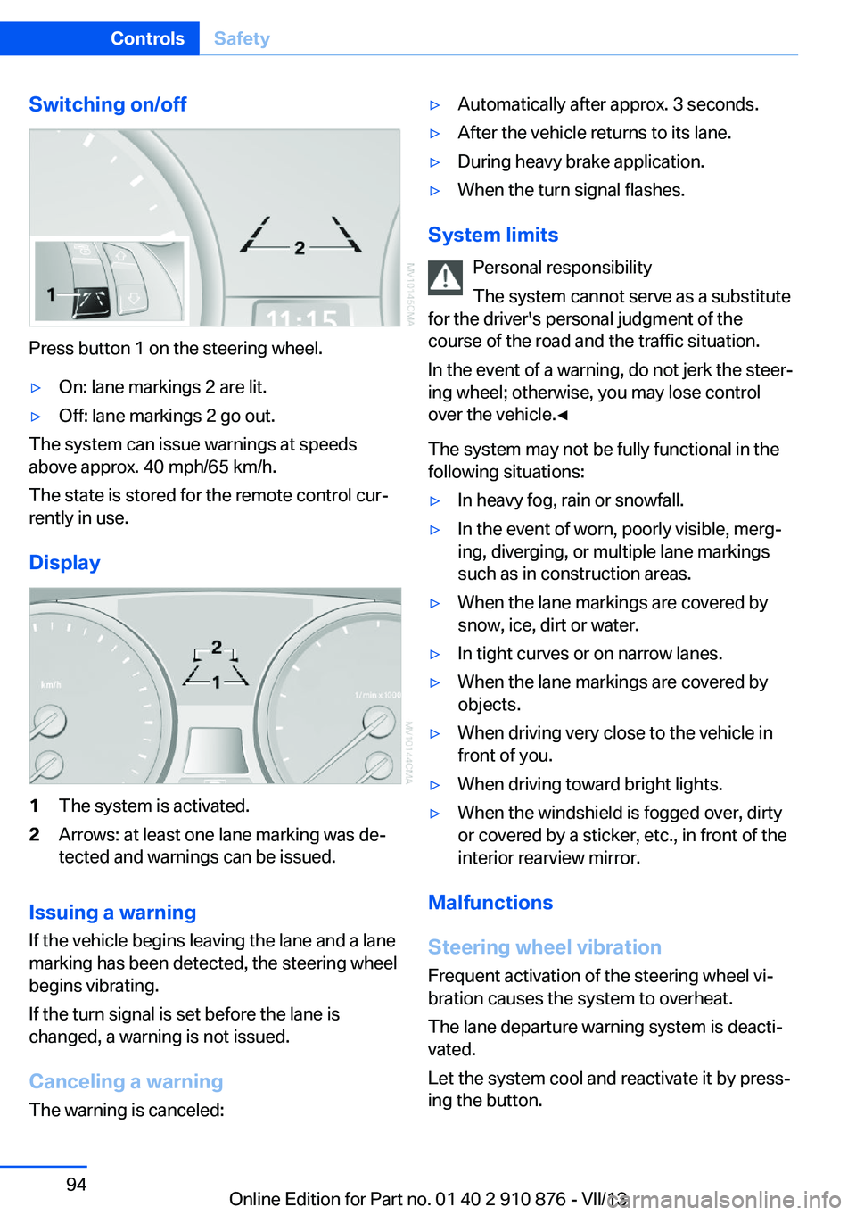
Press button 1 on the steering wheel.
▷On: lane markings 2 are lit.▷Off: lane markings 2 go out.
The system can issue warnings at speeds
above approx. 40 mph/65 km/h.
The state is stored for the remote control cur‐
rently in use.
Display
1The system is activated.2Arrows: at least one lane marking was de‐
tected and warnings can be issued.
Issuing a warning
If the vehicle begins leaving the lane and a lane
marking has been detected, the steering wheel
begins vibrating.
If the turn signal is set before the lane is
changed, a warning is not issued.
Canceling a warning The warning is canceled:
▷Automatically after approx. 3 seconds.▷After the vehicle returns to its lane.▷During heavy brake application.▷When the turn signal flashes.
System limits
Personal responsibility
The system cannot serve as a substitute
for the driver's personal judgment of the
course of the road and the traffic situation.
In the event of a warning, do not jerk the steer‐
ing wheel; otherwise, you may lose control
over the vehicle.◀
The system may not be fully functional in the
following situations:
▷In heavy fog, rain or snowfall.▷In the event of worn, poorly visible, merg‐
ing, diverging, or multiple lane markings
such as in construction areas.▷When the lane markings are covered by
snow, ice, dirt or water.▷In tight curves or on narrow lanes.▷When the lane markings are covered by
objects.▷When driving very close to the vehicle in
front of you.▷When driving toward bright lights.▷When the windshield is fogged over, dirty
or covered by a sticker, etc., in front of the
interior rearview mirror.
Malfunctions
Steering wheel vibration
Frequent activation of the steering wheel vi‐
bration causes the system to overheat.
The lane departure warning system is deacti‐
vated.
Let the system cool and reactivate it by press‐
ing the button.
Seite 94ControlsSafety94
Online Edition for Part no. 01 40 2 910 876 - VII/13
Page 95 of 323
Camera
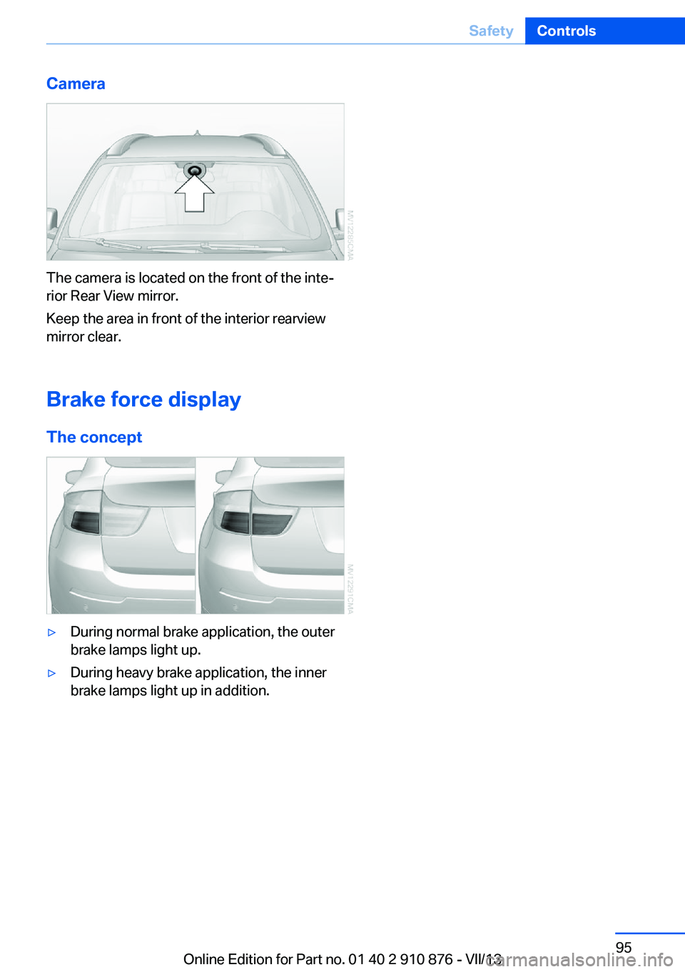
The camera is located on the front of the inte‐
rior Rear View mirror.
Keep the area in front of the interior rearview
mirror clear.
Brake force display The concept
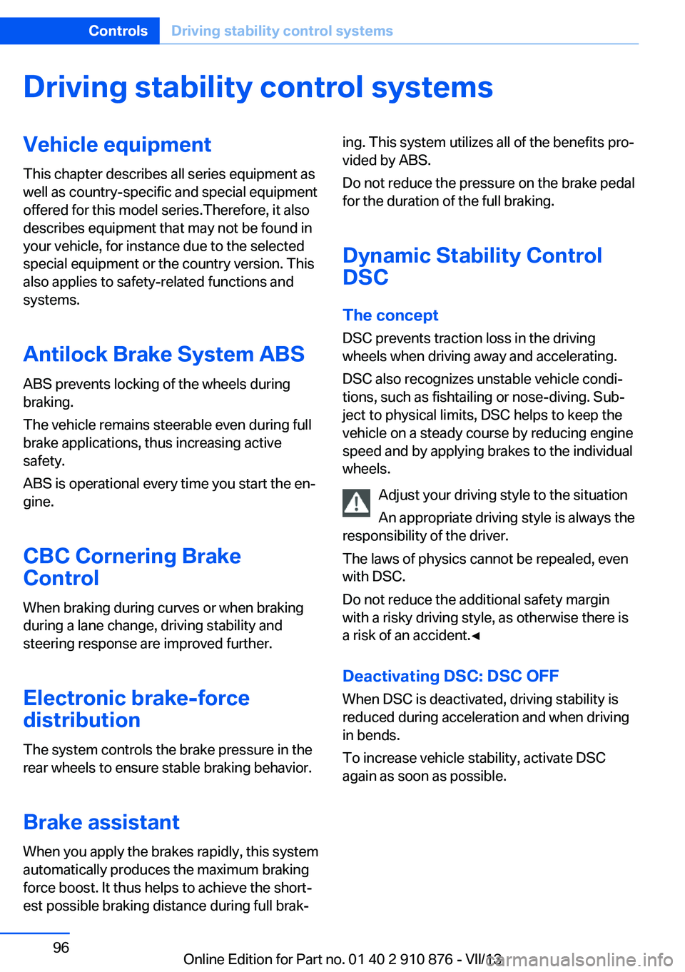
▷During normal brake application, the outer
brake lamps light up.▷During heavy brake application, the inner
brake lamps light up in addition.Seite 95SafetyControls95
Online Edition for Part no. 01 40 2 910 876 - VII/13
Page 96 of 323
Driving stability control systemsVehicle equipmentThis chapter describes all series equipment as
well as country-specific and special equipment
offered for this model series.Therefore, it also
describes equipment that may not be found in
your vehicle, for instance due to the selected
special equipment or the country version. This
also applies to safety-related functions and
systems.
Antilock Brake System ABS
ABS prevents locking of the wheels during
braking.
The vehicle remains steerable even during full
brake applications, thus increasing active
safety.
ABS is operational every time you start the en‐
gine.
CBC Cornering Brake
Control
When braking during curves or when braking
during a lane change, driving stability and
steering response are improved further.
Electronic brake-force
distribution
The system controls the brake pressure in the
rear wheels to ensure stable braking behavior.
Brake assistantWhen you apply the brakes rapidly, this system
automatically produces the maximum braking
force boost. It thus helps to achieve the short‐
est possible braking distance during full brak‐ing. This system utilizes all of the benefits pro‐
vided by ABS.
Do not reduce the pressure on the brake pedal
for the duration of the full braking.
Dynamic Stability Control DSC
The concept
DSC prevents traction loss in the driving
wheels when driving away and accelerating.
DSC also recognizes unstable vehicle condi‐
tions, such as fishtailing or nose-diving. Sub‐
ject to physical limits, DSC helps to keep the
vehicle on a steady course by reducing engine
speed and by applying brakes to the individual
wheels.
Adjust your driving style to the situation
An appropriate driving style is always the
responsibility of the driver.
The laws of physics cannot be repealed, even
with DSC.
Do not reduce the additional safety margin
with a risky driving style, as otherwise there is
a risk of an accident.◀
Deactivating DSC: DSC OFF
When DSC is deactivated, driving stability is
reduced during acceleration and when driving
in bends.
To increase vehicle stability, activate DSC
again as soon as possible.Seite 96ControlsDriving stability control systems96
Online Edition for Part no. 01 40 2 910 876 - VII/13
Page 97 of 323
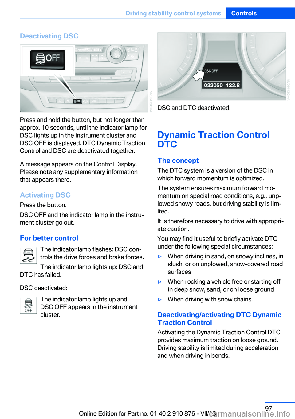
Deactivating DSC
Press and hold the button, but not longer than
approx. 10 seconds, until the indicator lamp for
DSC lights up in the instrument cluster and
DSC OFF is displayed. DTC Dynamic Traction
Control and DSC are deactivated together.
A message appears on the Control Display.
Please note any supplementary information
that appears there.
Activating DSC
Press the button.
DSC OFF and the indicator lamp in the instru‐
ment cluster go out.
For better control The indicator lamp flashes: DSC con‐
trols the drive forces and brake forces.
The indicator lamp lights up: DSC and
DTC has failed.
DSC deactivated: The indicator lamp lights up and
DSC OFF appears in the instrument
cluster.
DSC and DTC deactivated.
Dynamic Traction Control
DTC
The concept The DTC system is a version of the DSC in
which forward momentum is optimized.
The system ensures maximum forward mo‐
mentum on special road conditions, e.g., unp‐
lowed snowy roads, but driving stability is lim‐
ited.
It is therefore necessary to drive with appropri‐
ate caution.
You may find it useful to briefly activate DTC
under the following special circumstances:
▷When driving in sand, on snowy inclines, in
slush, or on unplowed, snow-covered road
surfaces▷When rocking a vehicle free or starting off
in deep snow, sand, or on loose ground▷When driving with snow chains.
Deactivating/activating DTC Dynamic
Traction Control
Activating the Dynamic Traction Control DTC
provides maximum traction on loose ground.
Driving stability is limited during acceleration
and when driving in bends.
Seite 97Driving stability control systemsControls97
Online Edition for Part no. 01 40 2 910 876 - VII/13
Page 98 of 323
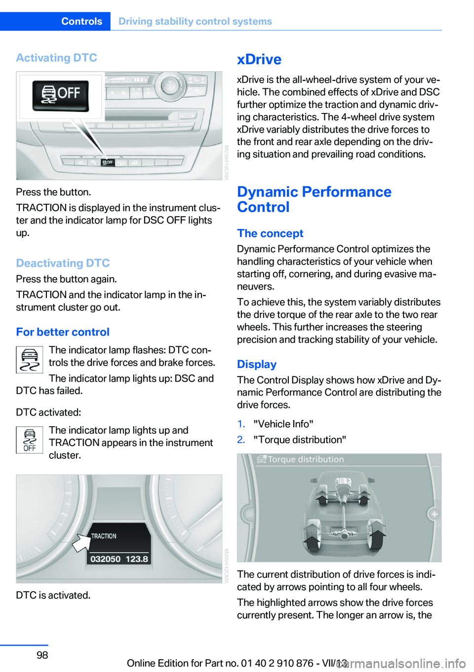
Activating DTC
Press the button.
TRACTION is displayed in the instrument clus‐
ter and the indicator lamp for DSC OFF lights
up.
Deactivating DTC
Press the button again.
TRACTION and the indicator lamp in the in‐
strument cluster go out.
For better control The indicator lamp flashes: DTC con‐
trols the drive forces and brake forces.
The indicator lamp lights up: DSC and
DTC has failed.
DTC activated: The indicator lamp lights up and
TRACTION appears in the instrument
cluster.
DTC is activated.
xDrive
xDrive is the all-wheel-drive system of your ve‐
hicle. The combined effects of xDrive and DSC
further optimize the traction and dynamic driv‐
ing characteristics. The 4-wheel drive system
xDrive variably distributes the drive forces to
the front and rear axle depending on the driv‐
ing situation and prevailing road conditions.
Dynamic Performance
Control
The concept Dynamic Performance Control optimizes the
handling characteristics of your vehicle when
starting off, cornering, and during evasive ma‐
neuvers.
To achieve this, the system variably distributes
the drive torque of the rear axle to the two rear
wheels. This further increases the steering
precision and tracking stability of your vehicle.
Display The Control Display shows how xDrive and Dy‐
namic Performance Control are distributing the
drive forces.1."Vehicle Info"2."Torque distribution"
The current distribution of drive forces is indi‐
cated by arrows pointing to all four wheels.
The highlighted arrows show the drive forces
currently present. The longer an arrow is, the
Seite 98ControlsDriving stability control systems98
Online Edition for Part no. 01 40 2 910 876 - VII/13
Page 99 of 323
greater the drive forces in the associated
wheel.
The transparent arrows indicate the maximum
value the drive forces over the last 10 seconds.
Malfunction
Malfunctions are displayed via Check Control,
refer to page 76.
Hill Descent Control HDC The conceptHDC is a downhill driving assistant that auto‐
matically controls vehicle speed on steep
downhill gradients. The vehicle moves at ap‐
proximately walking speed without braking in‐
tervention by the driver.
You can activate the Hill Descent Control at
speeds below approx. 22 mph/35 km/h. When
moving downhill at speeds below approx.
22 mph/35 km/h, the vehicle reduces its speed
to approximately walking speed, approx.
5 mph/8 km/h and keeps it constant.
Only use HDC in transmission positions D or R.
Increasing or reducing speed
The speed can be changed in the range from
approx. 4 mph/6 km/h to ap‐
prox. 15 mph/25 km/h by pressing the acceler‐
ator or brake pedal lightly.
A target speed within the same range can be
specified using the lever of the cruise control.
On inclines over 10 %, you can reduce the
speed to approx. 3 mph/4 km/h. Pull the lever
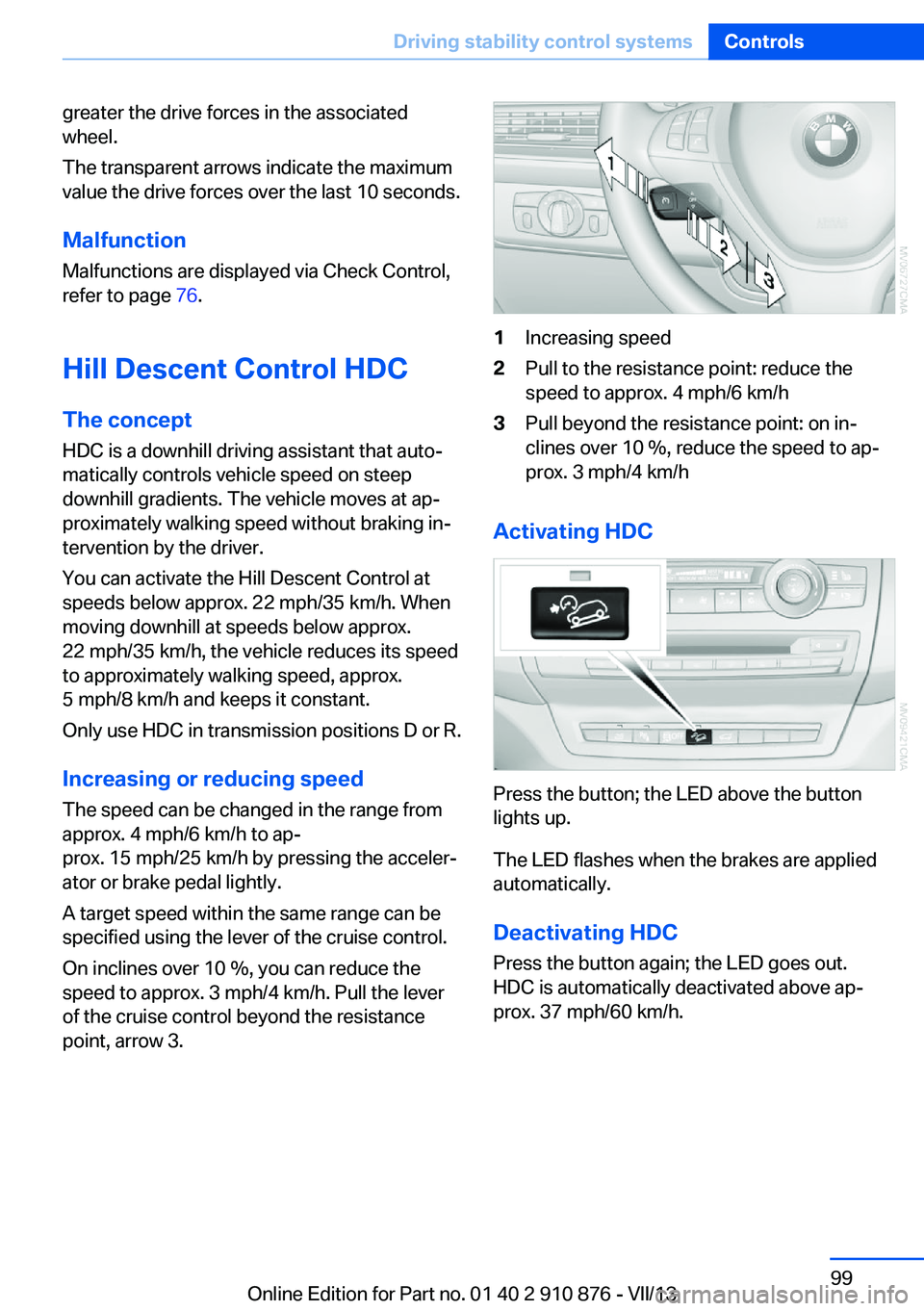
of the cruise control beyond the resistance point, arrow 3.1Increasing speed2Pull to the resistance point: reduce the
speed to approx. 4 mph/6 km/h3Pull beyond the resistance point: on in‐
clines over 10 %, reduce the speed to ap‐
prox. 3 mph/4 km/h
Activating HDC
Press the button; the LED above the button
lights up.
The LED flashes when the brakes are applied
automatically.
Deactivating HDC
Press the button again; the LED goes out.
HDC is automatically deactivated above ap‐
prox. 37 mph/60 km/h.
Seite 99Driving stability control systemsControls99
Online Edition for Part no. 01 40 2 910 876 - VII/13
Page 100 of 323
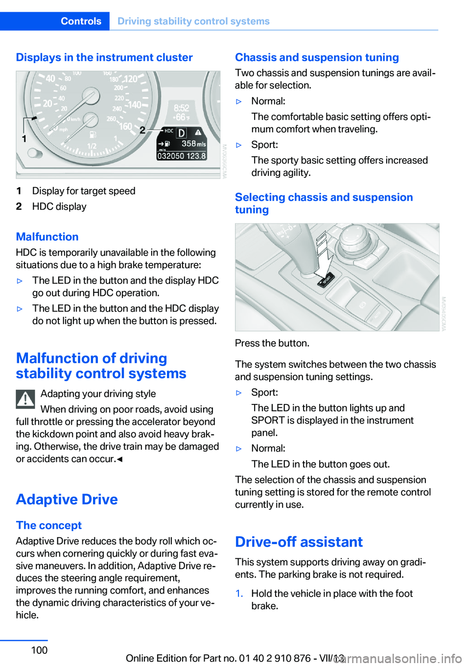
Displays in the instrument cluster1Display for target speed2HDC display
Malfunction
HDC is temporarily unavailable in the following
situations due to a high brake temperature:
▷The LED in the button and the display HDC
go out during HDC operation.▷The LED in the button and the HDC display
do not light up when the button is pressed.
Malfunction of driving
stability control systems
Adapting your driving style
When driving on poor roads, avoid using
full throttle or pressing the accelerator beyond
the kickdown point and also avoid heavy brak‐
ing. Otherwise, the drive train may be damaged
or accidents can occur.◀
Adaptive Drive The concept
Adaptive Drive reduces the body roll which oc‐
curs when cornering quickly or during fast eva‐
sive maneuvers. In addition, Adaptive Drive re‐
duces the steering angle requirement,
improves the running comfort, and enhances
the dynamic driving characteristics of your ve‐
hicle.
Chassis and suspension tuning
Two chassis and suspension tunings are avail‐
able for selection.▷Normal:
The comfortable basic setting offers opti‐
mum comfort when traveling.▷Sport:
The sporty basic setting offers increased
driving agility.
Selecting chassis and suspension
tuning
Press the button.
The system switches between the two chassis
and suspension tuning settings.
▷Sport:
The LED in the button lights up and
SPORT is displayed in the instrument
panel.▷Normal:
The LED in the button goes out.
The selection of the chassis and suspension
tuning setting is stored for the remote control
currently in use.
Drive-off assistant This system supports driving away on gradi‐
ents. The parking brake is not required.
1.Hold the vehicle in place with the foot
brake.Seite 100ControlsDriving stability control systems100
Online Edition for Part no. 01 40 2 910 876 - VII/13